Page 15 of 284

1
BEFORE DRIVING YOUR VEHICLE
3BEFORE DRIVING YOUR VEHICLE SAFETY CHECKS
!
B010A01P-GAT Be sure you know your vehicle and its equipment and how to use it safely. B010B01P-GAT Before entering the vehicle
o Check that windows, mirrors and
lights are clean.
o Check if any tire is low or flat.
o Look for fluid leaks.
o Check that area is clear if you're about to back up.
B010C03P-GAT After entering the vehicle
o Lock all doors.
o The driver and passengers are wear- ing properly adjusted seat belts.
o The head restraints are properly adjusted, if so equipped.
o Adjust inside and outside mirrors.
o Check warning lights for correct
operation, with the ignition key in the position "ON".
o Check all gauges, for normal opera- tion. WARNING: (Diesel only)
To ensure that sufficient vacuum exists within the brake system dur-ing cold weather start-up condi- tions, it is necessary to run the engine at idle after starting the en-gine. NOTE: Fluid levels, such as engine oil, engine coolant, brake fluid, and windshield washer fluid, should be checked daily and/or weekly, orwhenever you refuel. Further details are described in the "CONSUMER INFORMATION" sec-tion.
Biodiesel Commercially supplied biodiesel blends of no more than 5% biodiesel, com- monly known as "B5 biodiesel" may beused in your vehicle if it meets EN 14214 or equivalent specifications. (EN stands for "European Norm"). The useof biofuels made from rapeseed methyl ester (RME), fatty acid methyl ester (FAME), vegetable oil methyl ester(VME) etc. or mixing diesel with biodiesel will cause increased wear or damage to the engine and fuel system.Repair or replacement of worn or dam- aged components due to the use of non approved fuels will not be covered bythe manufactures warranty.
CAUTION:
o Never use any fuel, whether diesel or B5 biodiesel that fails to meetthe latest petroleum industry speci-fication.
o Never use any fuel additives or
treatments that are not recom-mended or approved by the ve- hicle manufacturer.
!
Page 70 of 284

2
INSTRUMENTS AND CONTROLS
3
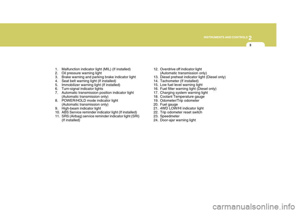
1. Malfunction indicator light (MIL) (If installed)
2. Oil pressure warning light
3. Brake warning and parking brake indicator light
4. Seat belt warning light (If installed)
5. Immobilizer warning light (If installed)
6. Turn-signal indicator lights
7. Automatic transmission position indicator light (Automatic transmission only)
8. POWER/HOLD mode indicator light
(Automatic transmission only)
9. High-beam indicator light
10. ABS Service reminder indicator light (If installed)
11. SRS (Airbag) service reminder indicator light (SRI) (If installed) 12. Overdrive off indicator light
(Automatic transmission only)
13. Diesel preheat indicator light (Diesel only)
14. Tachometer (If installed)
15. Low fuel level warning light
16. Fuel filter warning light (Diesel only)
17. Charging system warning light
18. Coolant Temperature gauge
19. Odometer/Trip odometer
20. Fuel gauge
21. 4WD LOW/Hl indicator light
22. Trip odometer reset switch
23. Speedmeter
24. Door-ajar warning light
Page 72 of 284
2
INSTRUMENTS AND CONTROLS
5
1. Fuel gauge
2. Coolant Temperature gauge
3. Malfunction indicator light (MIL) (If installed)
4. Oil pressure warning light
5. Brake warning and parking brake indicator light
6. Seat belt warning light (If installed)
7. Immobilizer warning light (If installed)
8. Automatic transmission position indicator light (Automatic transmission only)
9. POWER/HOLD mode indicator light
(Automatic transmission only)
10. High-beam indicator light
11. ABS Service reminder indicator light (If installed) 12. SRS (Airbag) service reminder indicator light (SRI)
(If installed)
13. Overdrive off indicator light (Automatic transmission only)
14. Speedmeter
15. Diesel pre-heat indicator light (Diesel only)
16. Low fuel level warning light
17. Fuel filter warning light (Diesel only)
18. Charging system warning light
19. Turn-signal indicator lights
20. Odometer/Trip odometer
21. 4WD LOW/Hl indicator light
22. Trip odometer reset switch
23. Door-ajar warning light
Page 74 of 284
2
INSTRUMENTS AND CONTROLS
7
1. Coolant Temperature gauge
2. Tachometer (If installed)
3. Turn-signal indicator lights
4. Speedmeter
5. Odometer
6. Fuel gauge
7. Low fuel level warning light
8. ABS Service reminder indicator light (If installed)
9. Malfunction indicator light (MIL) (If installed)
10. Fuel filter warning light (Diesel only)
11. Charging system warning light 12. Brake warning and parking brake indicator light
13. SRS (Airbag) service reminder indicator light (SRI)
(If installed)
14. Diesel pre-heat indicator light (Diesel only)
15. Door-ajar warning light
16. High-beam indicator light
17. Tripmeter reset switch
18. Tripmeter
19. Oil pressure warning light
20. Immobilizer warning light (If installed)
Page 79 of 284
2 INSTRUMENTS AND CONTROLS
12INSTRUMENT CLUSTER
B290A02A-AAT ENGINE COOLANT TEMPERATURE GAUGE Minibus/Van
C080A01A-GAT FUEL GAUGE Minibus/Van
The needle on the gauge indicates the approximate fuel level in the fuel tank. The fuel capacity is given in Section 9.
With Tachometer
Without Tachometer C080A02P
C080B02P With Tachometer
C090A02P
C090B02P
Without Tachometer
Truck
C080C02P
Page 80 of 284
2
INSTRUMENTS AND CONTROLS
13
C090C02P
!WARNING:
Never remove the radiator cap when the engine is hot. The engine cool- ant is under pressure and could erupt and cause severe burns. Waituntil the engine is cool before re- moving the radiator cap. The needle on the engine coolant tem- perature gauge should stay in the nor-mal range. If it moves across the dial to "H" (Hot), pull over and stop as soon as possible and turn off the engine. Thenopen the hood and after the engine has cooled, check the coolant level and the water pump drive belt. If you suspectcooling system trouble, have your cool- ing system checked by a Hyundai dealer as soon as possible. C040A02P-GAT SPEEDOMETER Minibus/Van
The speedometer indicates the vehicle's speed in kilometers per hour(km/h) or miles per hour (mph).
C040A02P C040A01P-1
Truck
Truck
Page 202 of 284

44IN CASE OF EMERGENCY
26
4. Check to see if the water pump drivebelt is missing. If it is not missing, check to see that it is tight. If the drive belt seems to be satisfactory, check for engine coolant leakingfrom the radiator, hoses or under the car. (If the air conditioning had been in use, it is normal for coldwater to be draining from it when you stop).
!WARNING:
While the engine is running, keep hair, hands, long hair and clothing away from moving parts such as the fan and drive belts to preventinjury.
!WARNING (Diesel only):
Never work on injection system with engine running or within 30 sec- onds after shutting off engine. High pressure pump, rail, injectors andhigh pressure pipes are subject to high pressure even after the engine stopped. The fuel jet produced byfuel leaks may cause serious in- jury, if it touch the body. People using pacemakers should not movethan 30cm closer to the ECU or wiring harness within the engine room while engine is running, sincethe high currents in the Common Rail system produce considerable magnetic fields.
5. If the water pump drive belt is broken or engine coolant is leaking out, stop the engine immediately and call the nearest Hyundai dealer for assis- tance.!WARNING:
Do not remove the radiator cap when the engine is hot. This can allow coolant to be blown out of the open- ing and cause serious burns.
6. If you cannot find the cause of the overheating, wait until the engine temperature has returned to nor-mal. Then, if the engine coolant has been lost, carefully add coolant to the reservoir (page 8-12) to bringthe fluid level in the reservoir up to the halfway mark.
7. Proceed with caution, keeping alert for further signs of overheating. Ifoverheating happens again, call a Hyundai dealer for assistance.
CAUTION:
Serious loss of engine coolant indi-cates there is a leak in the coolingsystem and this should be checked as soon as possible by a Hyundai dealer.
!
Page 205 of 284

4
CORROSION PREVENTION AND APPEARANCE CARE
29
4
IN CASE OF EMERGENCY
29
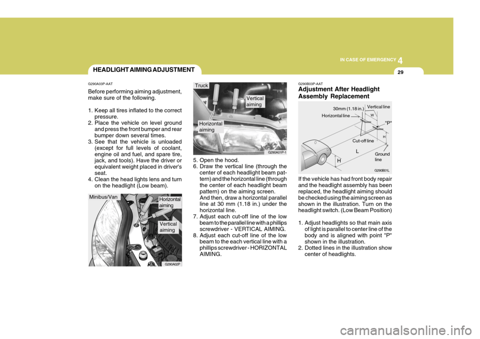
G290B03P-AAT Adjustment After Headlight Assembly Replacement If the vehicle has had front body repair and the headlight assembly has been replaced, the headlight aiming should be checked using the aiming screen asshown in the illustration. Turn on the headlight switch. (Low Beam Position)
1. Adjust headlights so that main axis
of light is parallel to center line of the body and is aligned with point "P"shown in the illustration.
2. Dotted lines in the illustration show
center of headlights.
5. Open the hood.
6. Draw the vertical line (through the
center of each headlight beam pat- tern) and the horizontal line (through the center of each headlight beam pattern) on the aiming screen.And then, draw a horizontal parallel line at 30 mm (1.18 in.) under the horizontal line.
7. Adjust each cut-off line of the low beam to the parallel line with a phillipsscrewdriver - VERTICAL AIMING.
8. Adjust each cut-off line of the low beam to the each vertical line with aphillips screwdriver - HORIZONTALAIMING.
Horizontal aiming
Verticalaiming
G290A01P-1
Truck
G290B01L
LW
H
H Cut-off line
Ground line
"P"
Horizontal line
30mm (1.18 in.) Vertical line
HEADLIGHT AIMING ADJUSTMENT
G290A03P-AAT Before performing aiming adjustment, make sure of the following.
1. Keep all tires inflated to the correct pressure.
2. Place the vehicle on level ground
and press the front bumper and rear bumper down several times.
3. See that the vehicle is unloaded
(except for full levels of coolant,engine oil and fuel, and spare tire, jack, and tools). Have the driver or equivalent weight placed in driver'sseat.
4. Clean the head lights lens and turn
on the headlight (Low beam).
Minibus/Van
G290A02P
Horizontal aiming
Verticalaiming