2007 Hyundai Getz temperature
[x] Cancel search: temperaturePage 422 of 463

DO-IT-YOURSELF MAINTENANCE 6- 11
SG050C2-E Engine Coolant Level The engine coolant level may be ob- served through the side of the plasticcoolant reservoir (expansion tank) when the engine is cold. If the level is below the "LOW" mark, add coolant of thecorrect concentration until the level is between the "LOW" and "Full" marks. If the level falls below the "LOW" mark ona regular basis despite being topped up, consult a Hyundai authorised repairer.
!WARNING:
The cooling fan is controlled by en- gine coolant temperature and may sometimes operate even when theengine is not running. Use extreme caution when working near the blades of the cooling fan so that youare not injured by a rotating fan blade. As the engine coolant tem- perature decreases, the fan will auto-matically shut off. This is a normal condition.
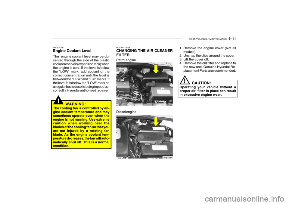
Petrol engine
HTB168
G070A01TB-EAT CHANGING THE AIR CLEANER FILTER
1. Remove the engine cover (Not all
models).
2. Unsnap the clips around the cover.
3. Lift the cover off.
4. Remove the old filter and replace to the new one. Genuine Hyundai Re- placement Parts are recommended.
CAUTION:
Operating your vehicle without aproper air filter in place can result in excessive engine wear.
!
Diesel engine
HTB168A
Page 426 of 463

DO-IT-YOURSELF MAINTENANCE 6- 15
G100B03A-GAT Checking the automatic transaxle fluid level
SG110A1-E AUTOMATIC TRANSAXLE FLUID The automatic transaxle fluid level should be checked and changed at those intervals prescribed in the main-tenance schedule. It is of paramount importance that only the specified fluid is used when replenishing or changingthe fluid. The use of other fluids may irreparably damage the transaxle and invalidate the manufacturers warranty.In addition the ingress of dirt or lint may prevent correct functioning of the transaxle and care must be exercisedto prevent the ingress of such matter.
CAUTION:
The transaxle fluid level must bechecked with the engine running and at normal operating temperature and therefore care must be exercised toprevent injury occurring through contact with rotating or hot parts of the engine.
! G110B04A-AAT Recommended Fluid Your Hyundai automatic transaxle is specially designed to operate withHyundai Genuine ATF SP-III, DIA- MOND ATF SP-III, SK ATF SP-III or other brands approved by Hyundai MotorCo., Damage caused by a nonspecified fluid is not covered by your new vehicle limited warranty.
The automatic transaxle fluid level should be checked regularly. Keep the vehicle on the level groundwith the parking brake applied and check the fluid level according to the following procedure.
1. Place the selector lever in N (Neu-tral) position and confirm the engine is running at normal idle speed.
2. After the transaxle is warmed up
sufficiently (fluid temperature70~80°C (158~176°F)), for example by 10 minutes usual driving, shift the selector lever through all positionsthen place the selector lever in N (Neutral) or P (Park) position.
HTB164
Page 427 of 463

6- 16 DO-IT-YOURSELF MAINTENANCE
if it touch the body. People using pacemakers should not move than 30cm closer to the ECU or wiringharness within the engine room while engine is running, since the high currents in the Common Rail systemproduce considerable magnetic fields.
!
CAUTION:
The automatic transaxle unit is a precision engineered assembly and correct operation is dependant uponthe exclusion of dirt and lint from the unit. Therefore, it is imperative that only lint free cloth (eg nylon) is usedfor wiping the dipstick and that the area around the dipstick is thor- oughly clean prior to level checkingor adding fluid. Fluid Capacity The total fluid capacity of the transaxle unit is 6.1 litres.
!
!
C090A03FC
Fluid level should be within "HOT" range
3. Confirm that the fluid level is in “HOT” range on the level gauge. If the fluid level is lower, add the specified fluid from the fill hole. If the fluid level is higher, drain the fluid from the drainhole.
4. If the fluid level is checked in cold
condition (fluid temperature 20~30°C(68~86°F)) add the fluid to “COLD” line and then recheck the fluid level according to the above step 2. WARNING:
The cooling fan is controlled by en-gine coolant temperature and maysometimes operate even when the engine is not running. Use extreme caution when working near theblades of the cooling fan so that you are not injured by a rotating fan blade. As the engine coolant tem-perature decreases, the fan will auto- matically shut off. This is a normal condition.
WARNING (Diesel only):
Never work on injection system withengine running or within 30 seconds after shutting off engine. High pres- sure pump, rail, injectors and highpressure pipes are subject to high pressure even after the engine stopped. The fuel jet produced byfuel leaks may cause serious injury,
Page 434 of 463

DO-IT-YOURSELF MAINTENANCE 6- 23
!
SG220A1-E ELECTRIC COOLING FANS
WARNING:
The cooling fan is controlled by en- gine coolant temperature and maysometimes operate even when the engine is not running. Use extreme caution when working near theblades of the cooling fan so that you are not injured by a rotating fan blade. As the engine coolant tem-perature decreases, the fan will auto- matically shut off. This is a normal condition. The engine cooling fan should operate before the temperature gauge reachesthe upper portion of the scale and the condenser fan should operate when- ever the air conditioning is in use. SG230B1-E POWER STEERING HOSES Power steering hoses should be checked for damage, deterioration and leakage at each service.
NOTE: Grinding noise from power steering pump may be heard immediately after the engine is started in extremelycold condition (below -4°F). If the noise stops during warm up, there is no abnormal function in the system.This is due to a power steering fluid characteristic in extremely cold con- ditions. FLUID RECOMMENDATION Only automatic transmission fluid meet- ing the specification of Dexron 2 should be used in the power steering system.SG230A2-E POWER STEERING FLUID LEVEL The power steering fluid level should be checked daily.To check the power steering fluid level, be sure the ignition is "OFF", then check to make certain that the powersteering fluid level is between the "MAX" and "MIN" level markings on the fluid reservoir.
HTB163
Page 446 of 463

7- 2 EMISSION CONTROL SYSTEMS
SH010A1-E EMISSION CONTROL SYSTEMS (Not all models) Depending upon the market for which the vehicle is destined, the emissioncontrol system will comprise one or more of the following emission con- trol devices.
1) Crankcase emission control sys-
tem
2) Evaporative emission control sys-
tem
3) Exhaust emission control systemIn order that the proper functioning of the emission control systems may be ensured, it is recommended that the vehicle is inspected and maintainedby a Hyundai authorised repairer in accordance with the maintenance schedule in this manual. SH010B1-E
1. Crankcase emission
controlsystem
The positive crankcase ventilation
system is employed to prevent airpollution caused by blow-by gasesbeing emitted from the crankcase by introducing fresh air to the crankcase through the air cleaner where thismixes with blow-by gases and then passes through the PCV valve into the intake manifold from where it sub-sequently enters the combustion chamber and is burned.
SH010C1-E
2. Evaporative emission control
system
The Evaporative Emission Control
System is designed to prevent fuel vapours from escaping into the atmo- sphere through the fuel tank ventila- tion system. SH010D1-E
3. Exhaust emission con trol
system
The exhaust emission control system
is a highly effective system whichcontrols exhaust emission while main- taining good vehicle performance. Whilst the engine is not running, fuel
vapours generated inside the fuel tank are absorbed and stored in a char-coal canister. When the engine is started, the vapours stored in the canister are drawn into the inductionsystem through the purge control sole- noid valve and are subsequently burned.
The purge control solenoid valve is
controlled by the ECU; when the en-gine coolant temperature is low or the engine is idling, the purge control valve is closed and fuel vapours re-main stored in the canister. Under normal running conditions when the engine is warm, the valve opens andthe vapours are drawn into the inlet tract and subsequently burned in the combustion chamber.
Page 447 of 463

EMISSION CONTROL SYSTEMS 7- 3
H020A01TB-EAT
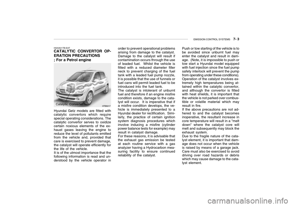
CATALYTIC CONVERTOR OP- ERATION PRECAUTIONS ; For a Petrol engine
Hyundai Getz models are fitted with
catalytic convertors which require special operating considerations. Thecatalytic convertor serves to oxidize certain noxious elements of the ex- haust gases leaving the engine toreduce the level of pollutants emitted from the vehicle and, provided that care is exercised to prevent damage,the catalyst will operate efficiently for the life of the vehicle.
It is of the utmost importance that the
following information is read and un-derstood by the vehicle operator in
HTB5017Catalytic Converter order to prevent operational problems arising from damage to the catalyst.
Damage to the catalyst will result if
contamination occurs through the use of leaded fuel. Whilst the vehicle isfitted with a reduced diameter filler neck to prevent charging of the fuel tank with a leaded fuel pump nozzle,it is possible that the use of funnels or fuel cans will permit leaded fuel to be introduced into the fuel tank.
The catalyst is intolerant of unburnt
fuel and therefore if an engine misfirecondition exists, damage to the cata-lyst will occur. It is imperative that if a misfire condition develops, the ve- hicle is immediately presented to aHyundai dealer for rectification. Simi- larly, the practice of certain ignition system diagnosis procedures whichinvolve inducing a misfire (cylinder power balance tests for example) may result in catalyst damage.
For these reasons, it is advisable that
the exhaust gas emission be testedat each routine service with a gas analyzer having a Hydrocarbon mea- suring facility to ensure continuedreliability of the catalyst. Push or tow starting of the vehicle is to be avoided since unburnt fuel may enter the catalyst and result in dam-age. (Note, it is impossible to push or tow start a Hyundai model equipped with fuel injection since the fuel pumpsafety interlock will prevent the pump from operating under these conditions). Operation of the catalyst involves ex- tremely high temperatures being at- tained within the catalytic convertor,and although the convertor is fitted with heat shields, it is important that the vehicle is not parked over combus-tible or volatile material which may result in fire. If the above precautions are not ad- hered to and the catalyst becomes inoperative, the resultant increase in core temperature will result in a "meltdown" where the catalyst core will melt and subsequently may block the exhaust system.Due to the fragile nature of the cata-lyst element, it is important that dam-age does not occur when the vehicle is raised by means of a garage jack. Care must also be exercised to avoiddriving over road hazards or debris which may cause damage to the cata- lyst element.