Page 170 of 463
WHAT TO DO IN AN EMERGENCY 3- 7
HTB230
D060A01A-AAT CHANGING A FLAT TIRE The procedure described on the fol- lowing pages can be used to rotatetires as well as to change a flat tire. When preparing to change a flat tire, check to be sure the gear selectorlever is in "P" (automatic transaxle) or reverse gear (manual transaxle) and that the parking brake is set, then:Flat tire
HTB156
D060C01A-AAT 2. Block the Wheel Block the wheel that is diagonally oppo- site from the flat to keep the vehicle from rolling when the car is raised onthe jack.
Take out the jack case and tool bag, then remove the spare tire from the luggage room. NOTE: The jack case is located on the spare tire in the vehicle.
Hang the luggage room mat to the mat hanger and remove the luggage under tray (If installed).
D060B01TB-GAT 1. Obtain Spare Tire and Tool
HTB224HTB296
Mat hanger
Page 171 of 463

3- 8 WHAT TO DO IN AN EMERGENCY
HTB149
HTB4003
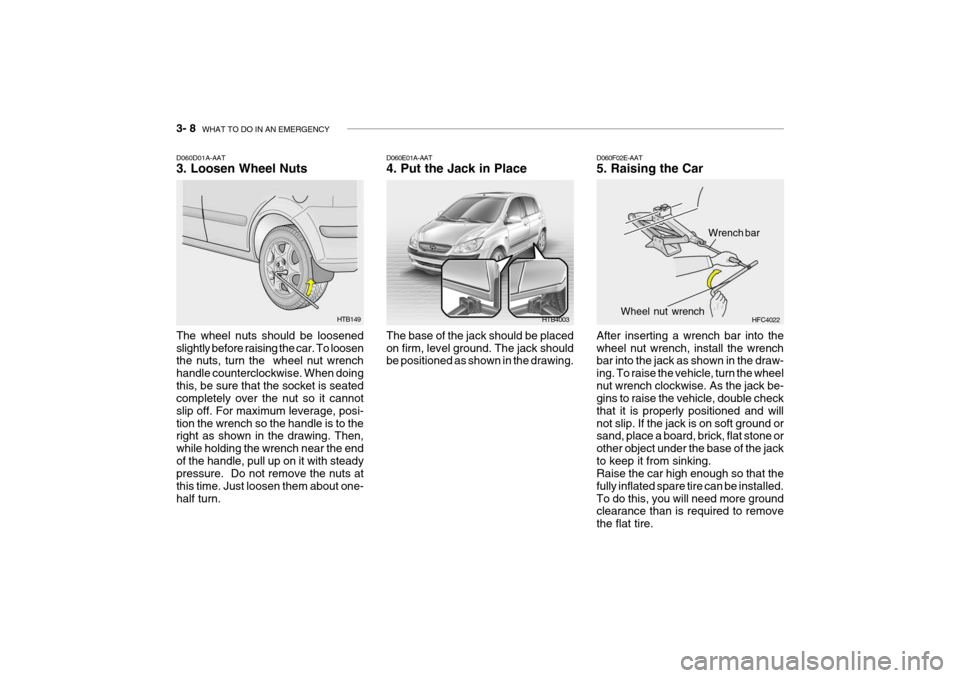
D060D01A-AAT 3. Loosen Wheel Nuts The wheel nuts should be loosened slightly before raising the car. To loosen the nuts, turn the wheel nut wrench handle counterclockwise. When doingthis, be sure that the socket is seated completely over the nut so it cannot slip off. For maximum leverage, posi-tion the wrench so the handle is to the right as shown in the drawing. Then, while holding the wrench near the endof the handle, pull up on it with steady pressure. Do not remove the nuts at this time. Just loosen them about one-half turn. D060E01A-AAT 4. Put the Jack in Place The base of the jack should be placed on firm, level ground. The jack should be positioned as shown in the drawing.
D060F02E-AAT 5. Raising the Car After inserting a wrench bar into the wheel nut wrench, install the wrench bar into the jack as shown in the draw- ing. To raise the vehicle, turn the wheelnut wrench clockwise. As the jack be- gins to raise the vehicle, double check that it is properly positioned and willnot slip. If the jack is on soft ground or sand, place a board, brick, flat stone or other object under the base of the jackto keep it from sinking. Raise the car high enough so that the fully inflated spare tire can be installed.To do this, you will need more ground clearance than is required to remove the flat tire.
HFC4022
Wrench bar
Wheel nut wrench
Page 172 of 463

WHAT TO DO IN AN EMERGENCY 3- 9
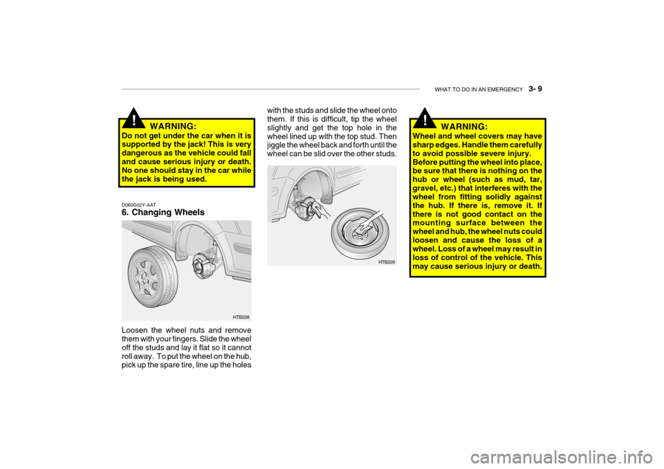
D060G02Y-AAT 6. Changing Wheels Loosen the wheel nuts and remove them with your fingers. Slide the wheel off the studs and lay it flat so it cannotroll away. To put the wheel on the hub, pick up the spare tire, line up the holesWARNING:
Do not get under the car when it issupported by the jack! This is very dangerous as the vehicle could falland cause serious injury or death. No one should stay in the car while the jack is being used.
!
HTB228 WARNING:
Wheel and wheel covers may have sharp edges. Handle them carefully to avoid possible severe injury.Before putting the wheel into place, be sure that there is nothing on the hub or wheel (such as mud, tar,gravel, etc.) that interferes with the wheel from fitting solidly against the hub. If there is, remove it. Ifthere is not good contact on the mounting surface between the wheel and hub, the wheel nuts couldloosen and cause the loss of a wheel. Loss of a wheel may result in loss of control of the vehicle. Thismay cause serious injury or death.
!
with the studs and slide the wheel onto them. If this is difficult, tip the wheel slightly and get the top hole in thewheel lined up with the top stud. Then jiggle the wheel back and forth until the wheel can be slid over the other studs.
HTB229
Page 173 of 463

3- 10 WHAT TO DO IN AN EMERGENCY
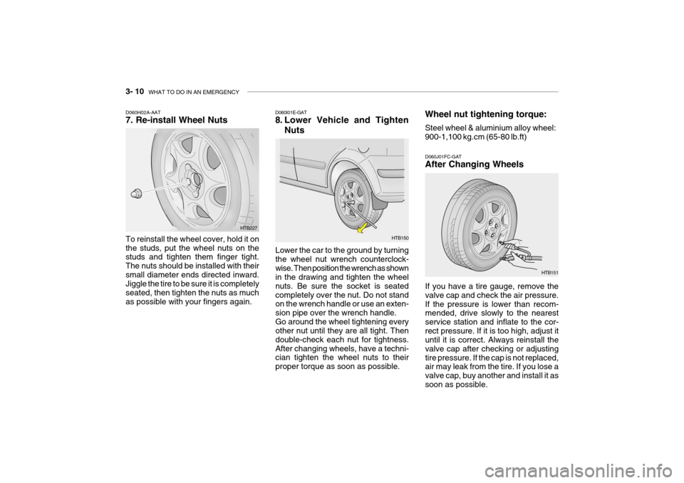
D060H02A-AAT 7. Re-install Wheel Nuts To reinstall the wheel cover, hold it on the studs, put the wheel nuts on the studs and tighten them finger tight. The nuts should be installed with theirsmall diameter ends directed inward. Jiggle the tire to be sure it is completely seated, then tighten the nuts as muchas possible with your fingers again. Lower the car to the ground by turningthe wheel nut wrench counterclock-wise. Then position the wrench as shown in the drawing and tighten the wheel nuts. Be sure the socket is seatedcompletely over the nut. Do not stand on the wrench handle or use an exten- sion pipe over the wrench handle.Go around the wheel tightening every other nut until they are all tight. Then double-check each nut for tightness.After changing wheels, have a techni- cian tighten the wheel nuts to their proper torque as soon as possible.
D060I01E-GAT
8. Lower Vehicle and Tighten
Nuts
D060J01FC-GATAfter Changing Wheels If you have a tire gauge, remove the valve cap and check the air pressure.If the pressure is lower than recom- mended, drive slowly to the nearest service station and inflate to the cor-rect pressure. If it is too high, adjust it until it is correct. Always reinstall the valve cap after checking or adjustingtire pressure. If the cap is not replaced, air may leak from the tire. If you lose a valve cap, buy another and install it assoon as possible.
HTB227 Wheel nut tightening torque: Steel wheel & aluminium alloy wheel: 900-1,100 kg.cm (65-80 lb.ft)
HTB150
HTB151
Page 174 of 463

WHAT TO DO IN AN EMERGENCY 3- 11
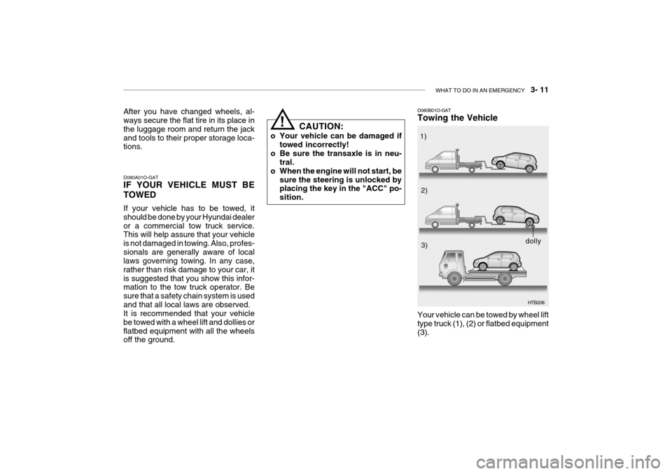
After you have changed wheels, al- ways secure the flat tire in its place in the luggage room and return the jackand tools to their proper storage loca- tions. D080A01O-GAT IF YOUR VEHICLE MUST BE TOWED If your vehicle has to be towed, it should be done by your Hyundai dealeror a commercial tow truck service. This will help assure that your vehicle is not damaged in towing. Also, profes-sionals are generally aware of local laws governing towing. In any case, rather than risk damage to your car, itis suggested that you show this infor- mation to the tow truck operator. Be sure that a safety chain system is usedand that all local laws are observed. It is recommended that your vehicle be towed with a wheel lift and dollies orflatbed equipment with all the wheels off the ground.
!
CAUTION:
o Your vehicle can be damaged if towed incorrectly!
o Be sure the transaxle is in neu- tral.
o When the engine will not start, be
sure the steering is unlocked by placing the key in the "ACC" po- sition. D080B01O-GAT Towing the Vehicle
HTB208
Your vehicle can be towed by wheel lift type truck (1), (2) or flatbed equipment(3). 1)
2)
3)
dolly
Page 224 of 463

DO-IT-YOURSELF MAINTENANCE 6- 29
If the vehicle has had front body repair and the headlight assembly has been replaced, the headlight aiming should be checked using the aiming screen asshown in the illustration. Turn on the headlight switch. (Low Beam Position)
1. Adjust headlights so that main axis
of light is parallel to center line of the body and is aligned with point "P"shown in the illustration.
2. Dotted lines in the illustration show
the center of headlights.
G290B01TB-GAT Adjustment After Headlight As- sembly Replacement
G290B01HR-1
L
W
H
H Cut-off line
Ground line
"P"
Horizontal line
30mm (1.18 in.) Vertical line
5. Open the hood.
6. Draw the vertical line (through the
center of each headlight beam pat-tern) and the horizontal line (throughthe center of each headlight beam pattern) on the aiming screen. And then, draw the horizontal paral- lel line at 30 mm (1.18 in.) under the horizontal line.
7. Adjust each cut-off line of the low beam to the parallel line with a phillipsscrewdriver - VERTICAL AIMING.
8. Adjust each cut-off line of the low
beam to each vertical line with aphillips screwdriver - HORIZONTAL AIMING. HTB269
Horizontal aiming
Vertical aiming
G290A01FC-GAT HEADLIGHT AIMING ADJUST- MENT Before performing aiming adjustment, make sure of the following.
1. Keep all tires inflated to the correct
pressure.
2. Place the vehicle on level ground and press the front bumper and rear bumper down several times. Place the vehicle at a distance of 3,000mm (118 in.) from the test wall.
3. See that the vehicle is unloaded
(except for full levels of coolant,engine oil and fuel, and spare tire, jack, and tools).
4. Clean the head lights lens and turn on the headlight (low beam).
Page 239 of 463

8. CONSUMER INFORMATION
Vehicle Identification Number (VIN) ............................................... 8-2
Engine number ............................................................................... 8-2
Recommended inflation pressures ................................................... 8-3
Snow tires ........................................................................................ 8-4
Tire chains ....................................................................................... 8-4
Tire rotation ...................................................................................... 8-5
Tire balancing ................................................................................... 8-5
Tire traction ...................................................................................... 8-5
When to replace tires ....................................................................... 8-6
Spare tire and tools .......................................................................... 8-6
8
Page 241 of 463

CONSUMER INFORMATION 8- 3
The engine number is stamped on the engine block as shown in the drawing. I020A01A-AAT TIRE INFORMATION The tires supplied on your new Hyundai are chosen to provide the best perfor-mance for normal driving. I030A03TB-GAT RECOMMENDED INFLATION PRESSURES The tire label located in the glove box gives the tire pressures recommended for your car.
These pressures were chosen to pro-vide the most satisfactory combination of ride comfort, tire wear and stabilityunder normal conditions. Tire pres- sures should be checked at least monthly. Proper tire inflation pressuresshould be maintained for these rea- sons:
o Lower-than-recommended tire pres-
sures cause uneven tread wear and poor handling.
o Higher-than-recommended tire pressures increase the chance ofdamage from impacts and causeuneven tread wear.
I010B02FC
HTB263
Diesel Engine
5.0Jx14 5.5Jx14 5.5Jx15 5.0Jx145.5Jx145.5Jx15
4.0Tx14 TIRE
SIZE
RIM
SIZE PRESSURE, kPa (PSI)
165/65R14175/65R14 185/55R15 175/65R14 185/55R15
T105/70D14 REAR
210(30) 220(32) 420(60) FRONT
230(33) 230(33) 420(60)
UP TO 2
PERSONS UP TO
MAX. LOAD
REAR
230(33) 230(33) 420(60)
FRONT210(30)
220(32)
420(60)
ENG- INE
GASO- LINE
DIE- SEL