2007 Hyundai Getz lock
[x] Cancel search: lockPage 365 of 463

DRIVING YOUR HYUNDAI 2- 5
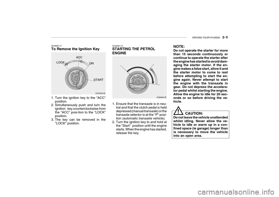
SC060A1-E STARTING THE PETROL ENGINE
C050A01E
1. Ensure that the transaxle is in neu- tral and that the clutch pedal is held depressed (manual transaxle) or the transaxle selector is at the "P" posi- tion (automatic transaxle vehicle).
2. Turn the ignition key to and hold at the "Start" position until the enginestarts. When the engine has started,release the key.
C070C01E
SC090D1-F To Remove the Ignition Key
1. Turn the ignition key to the "ACC"
position.
2. Simultaneously push and turn the
ignition key counterclockwise from the "ACC" posi-tion to the "LOCK" position.
3. The key can be removed in the "LOCK" position.LOCK
ACC
ON
START NOTE: Do not operate the starter for more than 15 seconds continuously or continue to operate the starter afterthe engine has started to avoid dam- aging the starter motor. If the en- gine makes a false start, allow it andthe starter motor to come to rest before attempting to start the en- gine again. Never attempt to startthe engine with the transaxle in gear. Do not depress the accelera- tor pedal whilst starting the engine.Allow the engine to idle for 20 sec- onds or so before driving the ve- hicle.
CAUTION:
Do not leave the vehicle unattendedwhilst idling. Never allow the ve-hicle to idle or warm up in a con- fined space (ie garage) longer than is necessary to move the vehicleinto an open area.
!
Page 366 of 463

2- 6 DRIVING YOUR HYUNDAI
C050B01HP
NOTE: If the engine were not started 10 seconds after the preheating is com- pleted, turn the ignition key once more to the "LOCK" position, andthen to the "ON" position, in order to preheat again.
C051A01O-EAT STARTING THE DIESEL ENGINE ENGINE COLD
o Turn the ignition key to position
"ON" and wait for the pre-heat indi- cator light to go out.
o Operate the starter until the engine
runs.
ENGINE WARM Operate the starter. If the engine does not respond on the first attempt, wait several seconds and try again usingthe pre-heat. C050B02S-GAT NORMAL CONDITIONS The Starting Procedure:
1. Insert key, and fasten the seat belt.
2. Depress the clutch pedal fully and
place the gearshift lever (manualtransaxle) in neutral or the selectorlever (automatic transaxle) in "P" (park) position.
3. After turning the ignition key to the "ON" position, make certain all warn-ing lights and gauges are function- ing properly before starting the en-gine.
4. On vehicles equipped with the die-
sel preheat indicator light, turn theignition key to the "ON" position. The diesel pre-heat indicator light will first illuminate in amber, andthen after a short time, the amber illumination will go off, indicating that preheating is completed. Amber lamp ON Amber lamp OFF
Page 370 of 463

2- 10 DRIVING YOUR HYUNDAI
YC090A1-E SELECTOR POSITIONS o P (Park): With the selector in this position, no drive is transmitted from the engine and the transaxle output and thereforethe front wheels locked. The engine may be started with the selector in this position.
!
CAUTION:
The selector must NEVER be shifted to the "P" position whilst the ve-hicle is in motion, otherwise seri- ous transaxle damage will result. DC110C1-E o R (Reverse): With the selector in this position, re- verse gear will be engaged. The en-gine may not be started with the selec- tor in this position.
CAUTION:
The selector must NEVER be shifted to the "R" position whilst the ve- hicle is in motion.
! DC110D1-E o N (Neutral): With the selector in this position, no gear is selected and no drive is trans-mitted from the engine. The engine may be started with the selector in this position.
!
CAUTION:
Do not coast with the selector at the "N" position. DC110E2-E o D (Drive): Bring the car to a complete stop before shifting the selector lever to "D" posi-tion. With the selector in this position, first gear will be engaged from rest and thetransmission will automatically upshift to second, third and fourth depending upon the vehicle speed, throttle posi-tion and the position of the overdrive switch. The engine may not be started with the selector in this position. DC110F1-E o 2 (Second Gear): With the selector in this position, first gear will be engaged from rest. Thetransmission will upshift to second gear depending upon the vehicle speed and throttle position. No upshift to third orfourth will occur. The engine may not be started with the selector in this position. DC110G2-E o L (Low Gear): With the selector in this position, first gear will be engaged from rest. No upshift will occur regardless of vehiclespeed and throttle opening. The en- gine may not be started with the selec- tor in this position.
!
CAUTION:
Do not move the selector to the "L" position when the vehicle speed is in excess of 50 m.p.h.
Page 374 of 463

2- 14 DRIVING YOUR HYUNDAI
!WARNING:
ABS will not prevent accidents due to improper or dangerous driving maneuvers. Even though vehicle control is improved during emer-gency braking, always maintain a safe distance between you and ob- jects ahead. Vehicle speeds shouldalways be reduced during extreme road conditions. The braking distance for carsequipped with an anti-lock braking system may be longer than for those without it in the following road con- ditions.
o Driving on rough, gravel or snow- covered roads.
o Driving with tyre chains installed.
o Driving on roads where the road surface is pitted or has differentsurface height.
These roads should be driven atreduced speeds. The safety featuresof an ABS equipped vehicle should not be tested by high speed driving or cornering. This could endangerthe safety of yourself or others.
SC140B2-E ANTI-LOCK BRAKE SYSTEM (Not all models) The Anti-Lock Brake System (ABS) is designed to prevent wheel lock-up during sudden braking or on hazard-ous road surfaces. The ABS control module monitors the wheel speed and controls the pressure applied to eachbrake. Thus, in emergency situations or on slick roads, ABS will increase vehicle control during braking. NOTE:
o A click sound may be heard in the
engine compartment when the ve- hicle begins to move after the en- gine is started. These conditions are normal and indicate that theanti-lock brake system (Electronic Stability Program) is functioning properly.
o During ABS operation, a slight pulsation may be felt in the brakepedal when the brakes are ap-plied. Also, a noise may be heard in the engine compartment whilst braking. These conditions arenormal and indicate that the anti- lock brake system is functioning properly.
C310A01JM-EAT ELECTRONIC STABILITY PROGRAM (ESP)(Not all models) The Electronic Stability Program (ESP) system is designed to stabilize the vehicle during cornering manuevers.ESP checks where you are steering and where the vehicle is actually going. ESP applies the brakes at individualwheels and intervenes in the engine management system to stabilize the vehicle. The Electronic Stability Program (ESP) system is an electronic system de-signed to help the driver maintain ve- hicle control under adverse conditions. C310A01TB-D
Page 378 of 463

2- 18 DRIVING YOUR HYUNDAI
SC170E1-E Windscreen Washers and Wip- ers The windscreen washer bottle should be filled with a solution of water and a proprietary winter screen wash addi-tive. The windscreen wipers should not be used if the blades are frozen to the windscreen or if they are coveredwith snow, before this is removed. NOTE: Never allow undiluted screen washer fluid additive to spill upon the paintwork or use engine cool- ant anti-freeze since damage to thepaintwork may result.
o When driving in extreme conditions,
the windscreen wiper blades may fail to clear the screen properly due to the formation of ice upon theblade edge. It will therefore be nec- essary to periodically remove such ice to restore their efficiency.
o If the power operated door mirrors become frozen, attempts to adjustthese may damage the mechanism.
ZC170D1-E Door Locks Should the door lock mechanism be- come frozen, a proprietary lock de-icer should be used. Alternatively, warm- ing the door key may thaw the doorlock. However, the key should be handled carefully to avoid burning the fingers.Never attempt to thaw a frozen door lock using hot water, since the water will eventually freeze and compoundthe problem. NOTE: The proper temperature for using the immobilizer key is from -40°F to 176°F (-40°C to 80°C). If you heat the immobilizer key over 176°F (80°C)to open the frozen lock, it may cause damage to the transponder in its head.
o The formation of snow or ice built up
inside the wheel arches may inter-fere with the road wheels or steeringmechanism. In such instances, un- usual noises or an increase in steer- ing effort may result. Therefore,ensure that the wheel arches are checked periodically and any accu- mulated snow or ice removed.
o It is advisable to carry emergency equipment including, torch, shovel,tow rope, blankets etc., if a journeyis to be undertaken into areas of severe road conditions.
Page 388 of 463

3- 6 WHAT TO DO IN AN EMERGENCY
SD050A2-E SPARE WHEEL (Not all models) The spare wheel is stored under the luggage compartment floor and is ac-cessed from within the luggage com- partment by lifting the carpet and the floor panel.To remove the spare wheel, unscrew the retainer, rotating this in an counter- clockwise direction and lift out the wheel.To replace the wheel, screw the retainer by hand until tight having located the wheel in the luggage compartment floorwell. The inflation pressure of the spare wheel should be checked at least monthly and whenever the wheel isfitted to the vehicle.
Inflation Pressure
Tyre Size
Spare Tyre Pressure
Full Size 30 psi 210 kPa
CAUTION:
o Do not use snow chains with your temporary spare tyre.
o Do not use more than one tempo- rary spare tyre at a time.
!
5. The temporary spare tyre should
not be used on any other wheels, nor should standard tyre, snow tyre,wheel covers or trim rings be used with the temporary spare wheel. If such use is attempted, damage tothese items or other car compo- nents may occur.
6. The temporary spare tyre pressure should be checked once a monthwhile the tyre is stored. D040B01FC-EAT SPARE TYRE FOR FULL SIZE The following instructions for the FULL SIZE spare tyre should be observed: Check inflation pressure as soon as possible after installing the spare tyre,and adjust to the specified pressure. The tyre pressure should be periodi- cally checked and maintained at thespecified pressure while the tyre is stored. Spare Tyre Pressure
Tyre Size Inflation Pressure
Full size 30 psi (210 kPa)
Page 390 of 463

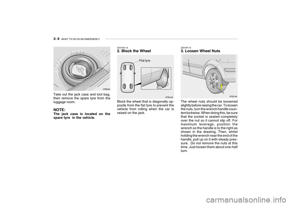
3- 8 WHAT TO DO IN AN EMERGENCY
HTB149
ZD070F1-E 3. Loosen Wheel Nuts The wheel nuts should be loosened slightly before raising the car. To loosen the nuts, turn the wrench handle coun- terclockwise. When doing this, be surethat the socket is seated completely over the nut so it cannot slip off. For maximum leverage, position thewrench so the handle is to the right as shown in the drawing. Then, whilst holding the wrench near the end of thehandle, pull up on it with steady pres- sure. Do not remove the nuts at this time. Just loosen them about one-halfturn.
Flat tyre
HTB156
SD070D1-E 2. Block the Wheel Block the wheel that is diagonally op- posite from the flat tyre to prevent the vehicle from rolling when the car is raised on the jack.
Take out the jack case and tool bag,then remove the spare tyre from the luggage room. NOTE: The jack case is located on the spare tyre in the vehicle.
HTB224
Page 391 of 463

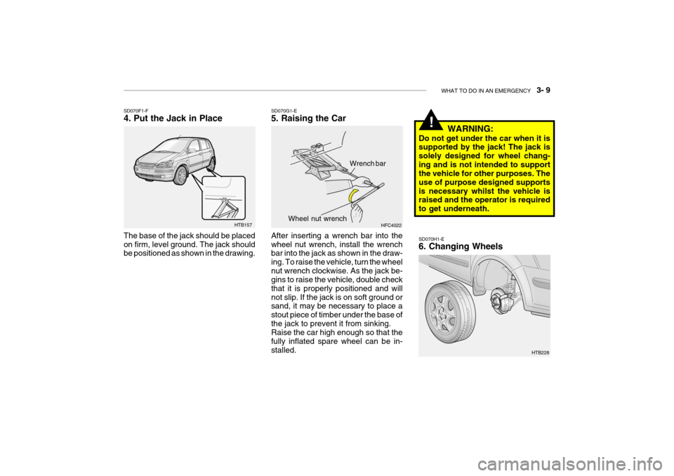
WHAT TO DO IN AN EMERGENCY 3- 9
!
SD070H1-E 6. Changing Wheels
HTB157
SD070F1-F 4. Put the Jack in Place The base of the jack should be placed on firm, level ground. The jack should be positioned as shown in the drawing.
SD070G1-E 5. Raising the Car After inserting a wrench bar into the wheel nut wrench, install the wrench bar into the jack as shown in the draw- ing. To raise the vehicle, turn the wheelnut wrench clockwise. As the jack be- gins to raise the vehicle, double check that it is properly positioned and willnot slip. If the jack is on soft ground or sand, it may be necessary to place a stout piece of timber under the base ofthe jack to prevent it from sinking. Raise the car high enough so that the fully inflated spare wheel can be in-stalled. HFC4022
Wrench bar
Wheel nut wrench
WARNING:
Do not get under the car when it is supported by the jack! The jack is solely designed for wheel chang-ing and is not intended to support the vehicle for other purposes. The use of purpose designed supportsis necessary whilst the vehicle is raised and the operator is required to get underneath.
HTB228