2007 Hyundai Getz ignition
[x] Cancel search: ignitionPage 375 of 463

DRIVING YOUR HYUNDAI 2- 15
!
It is not a substitute for safe driving practices. Factors including speed, road conditions and driver steering input canall affect whether ESP will be effective in preventing a loss of control. It is still your responsibility to drive and cornerat reasonable speeds and to leave a sufficient margin of safety.
WARNING:
Electronic stability program is a driv- ing aid; all normal precautions for driving in inclement weather and on slippery road surfaces should beobserved.
! CAUTION:
Driving with varying tyre or wheel size may cause the ESP system to malfunction. When replacing tyres,make sure they are the same size as your original tyres. C310D01JM-EAT Indicators and Warning The indicators should illuminate when the ignition key is turned to ON orSTART but should go out after approxi- mately 3 seconds. If the indicators do not illuminate, or theESP-OFF indicator does not go out after approximately 3 seconds, have the vehicle checked by Hyundaiauthorised repairer. Should there be any unusual conditions in the device whilst driving, ESP-OFF indicator illuminates as a warning. If ESP-OFF indicator illuminates, pullyour car to a safe place and stop the engine. Then, start the engine again to check ifthe ESP-OFF indicator goes out. If the indicator remains lit even after the engine has been started, have your car checked by Hyundai authorised repairer.
C310B01JM-AAT ESP ON/OFF Mode When the ESP is operating, the ESP indicator in the instrument cluster willblink. If you turn the system off by pressing the ESP switch, the ESP-OFF indica-tor will come on and stay on. In the ESP-OFF mode, the stability control will be deactivated. Adjust your drivingaccordingly. To turn the system back on, press the switch again. The ESP- OFF indicator should go off. NOTE: The ESP mode will automatically be turned ON after the engine is turned off and restarted.
Page 384 of 463

3- 2 WHAT TO DO IN AN EMERGENCY
HTB165
SD020B1-E IF THE ENGINE CANNOT BE CRANKED
1. If the vehicle is fitted with manual
transaxle, ensure that the clutch pedal is depressed whilst cranking the engine. If the vehicle is fitted with automatic transaxle, ensurethat the transaxle selector is at the "P" or"N" position.
2. Check the battery terminals and
connections to ensure that theseare clean and also tight.
3. If the ignition warning lights dim
when the engine is cranked and thebattery terminals have been checked, a discharged battery isindicated. SD020C1-F If Engine Turns Over Normally but Does Not Start
SD020A1-E IF THE ENGINE WILL NOT START Seek assistance from the nearest Hyundai authorised repairer with re- gard to the method of ignition and fuelsystem diagnosis.
!
HTB221
CAUTION:
If the engine refuses to start, no attempt should be made to push or tow start the vehicle. Vehicles withautomatic transaxle or fuel injec- tion will not be able to be started in this manner since no drive is trans-mitted through the automatic transaxle whilst the engine is not running, and in the case of fuelinjected derivatives, the fuel pump will not operate under tow start conditions. In addition, if the ve-hicle is equipped with an exhaust catalyst, damage to the catalyst may result if the vehicle is tow started. 4. Do not attempt to push or tow start
the vehicle, refer to "Jump Starting"for information regarding enginestarting when the battery is dis- charged.
1. Check fuel Level
2. Check all connectors at ignition coil and spark plugs. Replace any that may be discon- nected or loose.
3. Check fuel line in the engine com- partment.
4. If engine still refuses to start, call a
Hyundai authorised repairer or seek other qualified assistance.
Page 394 of 463

3- 12 WHAT TO DO IN AN EMERGENCY
!
!
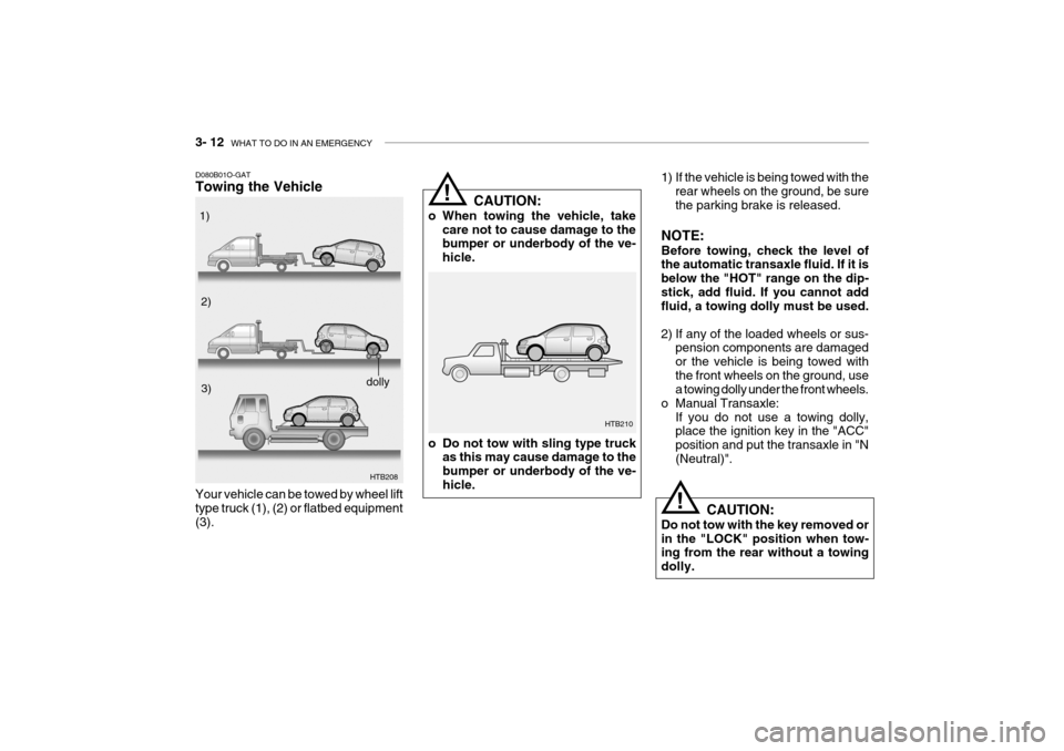
1) If the vehicle is being towed with the
rear wheels on the ground, be sure the parking brake is released.
NOTE: Before towing, check the level of the automatic transaxle fluid. If it is below the "HOT" range on the dip-stick, add fluid. If you cannot add fluid, a towing dolly must be used.
2) If any of the loaded wheels or sus- pension components are damaged or the vehicle is being towed withthe front wheels on the ground, use a towing dolly under the front wheels.
o Manual Transaxle:
If you do not use a towing dolly,place the ignition key in the "ACC" position and put the transaxle in "N(Neutral)".
CAUTION:
Do not tow with the key removed orin the "LOCK" position when tow- ing from the rear without a towing dolly.
CAUTION:
o When towing the vehicle, take care not to cause damage to the bumper or underbody of the ve- hicle.
o Do not tow with sling type truck as this may cause damage to thebumper or underbody of the ve-hicle. HTB210
D080B01O-GAT Towing the Vehicle
HTB208
Your vehicle can be towed by wheel lift type truck (1), (2) or flatbed equipment (3). 1)
2)
3)
dolly
Page 434 of 463

DO-IT-YOURSELF MAINTENANCE 6- 23
!
SG220A1-E ELECTRIC COOLING FANS
WARNING:
The cooling fan is controlled by en- gine coolant temperature and maysometimes operate even when the engine is not running. Use extreme caution when working near theblades of the cooling fan so that you are not injured by a rotating fan blade. As the engine coolant tem-perature decreases, the fan will auto- matically shut off. This is a normal condition. The engine cooling fan should operate before the temperature gauge reachesthe upper portion of the scale and the condenser fan should operate when- ever the air conditioning is in use. SG230B1-E POWER STEERING HOSES Power steering hoses should be checked for damage, deterioration and leakage at each service.
NOTE: Grinding noise from power steering pump may be heard immediately after the engine is started in extremelycold condition (below -4°F). If the noise stops during warm up, there is no abnormal function in the system.This is due to a power steering fluid characteristic in extremely cold con- ditions. FLUID RECOMMENDATION Only automatic transmission fluid meet- ing the specification of Dexron 2 should be used in the power steering system.SG230A2-E POWER STEERING FLUID LEVEL The power steering fluid level should be checked daily.To check the power steering fluid level, be sure the ignition is "OFF", then check to make certain that the powersteering fluid level is between the "MAX" and "MIN" level markings on the fluid reservoir.
HTB163
Page 442 of 463

DO-IT-YOURSELF MAINTENANCE 6- 31
G200C02TB-GAT FUSE PANEL DESCRIPTION Engine Compartment
PROTECTED COMPONENTS
Ignition Switch Ignition Switch, Start Relay
Fuel pump, Alternator, ECM
Radiator FanHeadlight, Defogger RelayABSC/lighterAuto Fuel Cut Switch ABS ABS
Blower, Blower Motor
Power WindowElectronic power steeringECMECMA/CON, Fuel PumpInjectorA/ConditionerHornAlternator
FUSE RATING
30A30A30A30A50A10A25A15A10A20A40A30A30A50A10A20A10A15A10A10A
100A
DESCRIPTION
IGN 2IGN 1ECURAD
BATT ABS
C/LIGHTER F/PUMPECU-BABS1ABS2BLW
P/WDW EPS
ECU-1ECU-2 SNSR INJ
A/CON HORN BATT
Note: Not all fuse panel descriptions in this manual may be applicable to your vehicle. It is accurate at the time of printing. When you inspect the fuse box on your vehicle, refer to the fuse box label.
Gasoline Engine
G200C01TB
Page 443 of 463

6- 32 DO-IT-YOURSELF MAINTENANCE
G250C01TB-GAT FUSE PANEL DESCRIPTION Engine Compartment
PROTECTED COMPONENTS
Ignition Switch Ignition Switch, Start Relay
Fuel pump, Alternator, ECMFFHS
Radiator FanHeadlight, Defogger RelayABSC/lighterAuto Fuel Cut Switch ABS ABS
Blower, Blower Motor
Power WindowElectronic power steeringECMECMA/CON, Fuel PumpInjectorA/ConditionerHornAlternator
FUSE RATING
30A30A30A30A30A50A10A25A15A10A20A40A30A30A50A10A20A10A15A10A10A
100A
DESCRIPTION
IGN 2IGN 1ECU
FFHS RAD
BATT ABS
C/LIGHTER F/PUMPECU-BABS1ABS2BLW
P/WDW EPS
ECU-1ECU-2 SNSR INJ
A/CON HORN BATT
Note: Not all fuse panel descriptions in this manual may be applicable to your vehicle. It is accurate at the time of printing. When you inspect the fuse box on your vehicle, refer to the fuse box label.
Diesel Engine
G200C01TB-2
Page 444 of 463

DO-IT-YOURSELF MAINTENANCE 6- 33
G200E01TB
G200E02TB-GAT Inner Panel
FUSE RATING
10A 10A10A15A10A10A 20A 15A10A 20A 10A 15A20A10A10A10A 30A 15A10A15A15A15APROTECTED COMPONENTS
Air conditioner
Stop/Tail Light (LH) A/Bag IndicatorAudio, Electronic Outside Mirror
Turn signal Light, Back-up Light
Stop/Tail Light (RH)Cluster
Power outlet PCM, ABS controlAir BagDoor Lock System, SunroofRear Wiper Motor
Start Relay, 9oTheft alarm system Seat Warmer Rear window DefrosterECM
Hazard Warning Light, ETACM Front Wiper Motor Rear Fog Light
Fog light, ETACM, Power Window, Headlight leveling Device
Blower, SunroofRear window DefrosterHeadlight (RH)Front Fog Light
High Beam Light Indicator, Headlight (LH) Room Lamp, Audio, Cluster
DESCRIPTION
A/C SW
TAIL LH
A/BAG IND
AUDIO
T/SIG
TAIL RH
CLUSTER
P/OUTLET ECU 1
A/BAG
D/LOCK
RR/WPR STARTS/HTD
HTD MIR ECU2
STOP
HAZARD
FRT WPR R/FOG
IGNITION BLOWER PR HTD
H/LP RH F/FOG
H/LP LH
POWER CONN & R/LP
Page 447 of 463

EMISSION CONTROL SYSTEMS 7- 3
H020A01TB-EAT
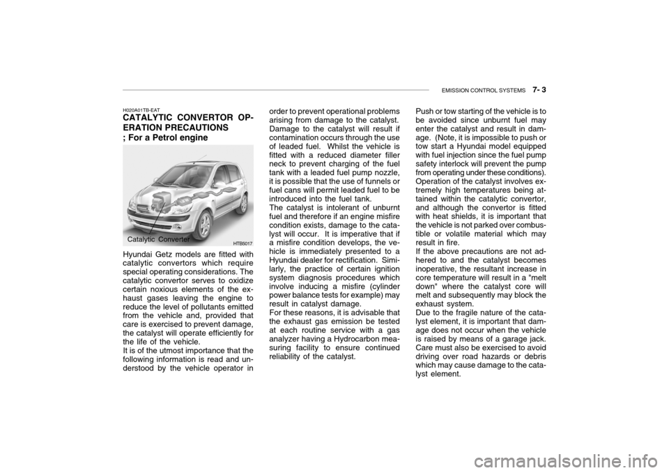
CATALYTIC CONVERTOR OP- ERATION PRECAUTIONS ; For a Petrol engine
Hyundai Getz models are fitted with
catalytic convertors which require special operating considerations. Thecatalytic convertor serves to oxidize certain noxious elements of the ex- haust gases leaving the engine toreduce the level of pollutants emitted from the vehicle and, provided that care is exercised to prevent damage,the catalyst will operate efficiently for the life of the vehicle.
It is of the utmost importance that the
following information is read and un-derstood by the vehicle operator in
HTB5017Catalytic Converter order to prevent operational problems arising from damage to the catalyst.
Damage to the catalyst will result if
contamination occurs through the use of leaded fuel. Whilst the vehicle isfitted with a reduced diameter filler neck to prevent charging of the fuel tank with a leaded fuel pump nozzle,it is possible that the use of funnels or fuel cans will permit leaded fuel to be introduced into the fuel tank.
The catalyst is intolerant of unburnt
fuel and therefore if an engine misfirecondition exists, damage to the cata-lyst will occur. It is imperative that if a misfire condition develops, the ve- hicle is immediately presented to aHyundai dealer for rectification. Simi- larly, the practice of certain ignition system diagnosis procedures whichinvolve inducing a misfire (cylinder power balance tests for example) may result in catalyst damage.
For these reasons, it is advisable that
the exhaust gas emission be testedat each routine service with a gas analyzer having a Hydrocarbon mea- suring facility to ensure continuedreliability of the catalyst. Push or tow starting of the vehicle is to be avoided since unburnt fuel may enter the catalyst and result in dam-age. (Note, it is impossible to push or tow start a Hyundai model equipped with fuel injection since the fuel pumpsafety interlock will prevent the pump from operating under these conditions). Operation of the catalyst involves ex- tremely high temperatures being at- tained within the catalytic convertor,and although the convertor is fitted with heat shields, it is important that the vehicle is not parked over combus-tible or volatile material which may result in fire. If the above precautions are not ad- hered to and the catalyst becomes inoperative, the resultant increase in core temperature will result in a "meltdown" where the catalyst core will melt and subsequently may block the exhaust system.Due to the fragile nature of the cata-lyst element, it is important that dam-age does not occur when the vehicle is raised by means of a garage jack. Care must also be exercised to avoiddriving over road hazards or debris which may cause damage to the cata- lyst element.