2007 Hyundai Accent fuel cap
[x] Cancel search: fuel capPage 74 of 282

1FEATURES OF YOUR HYUNDAI
62
B290A01MC-GAT
Engine Coolant Tempera-
ture Indicator Light
(If Installed)
WARNING:
Never remove the radiator cap when the engine is hot. The engine coolant is under pressure and could erupt and cause severe burns. Wait untilthe engine is cool before removing the radiator cap.
!
These indicator lights show the tem- perature of the engine coolant when the ignition switch is ON. Red indicator light illuminates if the temperature of theengine coolant is above 123±3°C (253.4±37.4°F). Blue indicator light Illu- minates if the temperature of the enginecoolant is below 55±3°C (131±37.4°F). If the red indicator light illuminates, pull over and stop as soon as possible andturn off the engine. Then open the hood and check the coolant level (See "If the engine overheats" on the page 3-4.) andthe water pump drive belt. If you sus- pect cooling system trouble, have your cooling system checked by a Hyundaidealer as soon as possible.
If the Emission Control SystemMalfunction Indicator Light beginsto flash ON and OFF, potential catalytic converter damage is pos- sible which could result in loss ofengine power. Have the Engine Control System inspected as soon as possible by an authorizedHyundai dealer (Gasoline Engine).
o In case the injection quantity ad-
justment related error occurred,the Emission Control System Mal- function Indicator Light begins to flash ON and OFF. Continuousdriving with this status could re- sult in abnormal engine power loss (or power increase), combus-tion noise and poor emission. If this occurs, have your vehicle checked by an authorized Hyundaidealer (Diesel Engine).
B260N01MC-GAT Malfunction Indicator Light (If Installed)
This light illuminates when there is a malfunction of an exhaust gas relatedcomponent, and the system is not func- tioning properly so that the exha ust gas
regulation values are not satisfied. This light will also illuminate when the ignition
key is turned to the "ON" position, and then it will go out in a few seconds after
the engine is started. If it illuminates
while driving, or does not illuminate whenthe ignition key is turned to the "ON"position, take your car to your nearest authorized Hyundai dealer and have the system checked.
CAUTION:
o Prolonged driving with the Emis- sion Control System Malfunction Indicator Light illuminated may cause damage to the emission control systems which could ef-fect drivability or fuel economy.!
Page 78 of 282

1FEATURES OF YOUR HYUNDAI
66
B270A01A-AAT BRAKE PAD WEAR WARNING SOUND The front disc brake pads have wear indicators that should make a high- pitched squealing or scraping noisewhen new pads are needed. The sound may come and go or be heard all the time when the vehicle is moving. It mayalso be heard when the brake pedal is pushed down firmly. Excessive rotor damage will result if the worn pads arenot replaced. See your Hyundai dealer immediately.
!
B290A02A-AAT ENGINE COOLANT TEMPERA- TURE GAUGE (If Installed)
WARNING:
Never remove the radiator cap when the engine is hot. The engine coolant is under pressure and could erupt and cause severe burns. Wait untilthe engine is cool before removing the radiator cap.
B290A01MC
INSTRUMENT CLUSTER
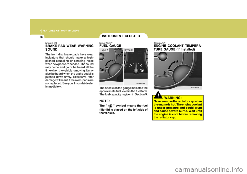
The needle on the gauge indicates the approximate fuel level in the fuel tank. The fuel capacity is given in Section 9. NOTE: The "
" symbol means the fuel
filler lid is placed on the left side of the vehicle.
B280A01TG-AAT FUEL GAUGE
B280A01MC
Type AType B
Page 104 of 282

1FEATURES OF YOUR HYUNDAI
92
WARNING:
o Fuel vapors are dangerous. Be- fore refueling, always stop the en- gine and never allow sparks or open flames near the filler area. If you need to replace the filler cap,use a genuine Hyundai replace- ment part. If you open the fuel filler cap dur-ing high ambient temperatures, a slight "pressure sound" may be heard. This is normal and not acause for concern. Whenever you open the fuel filler cap, turn it slowly.!
REMOTE FUEL-FILLER LID RELEASE
B560A01MC-GAT
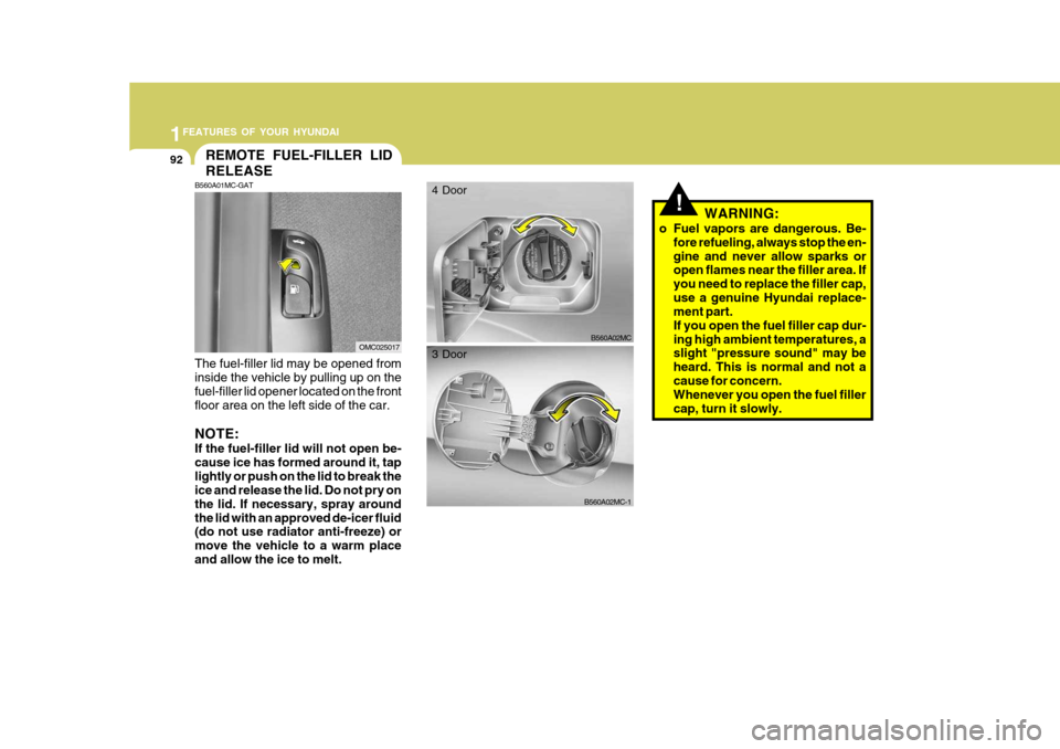
The fuel-filler lid may be opened from inside the vehicle by pulling up on the fuel-filler lid opener located on the front floor area on the left side of the car. NOTE: If the fuel-filler lid will not open be- cause ice has formed around it, taplightly or push on the lid to break the ice and release the lid. Do not pry on the lid. If necessary, spray aroundthe lid with an approved de-icer fluid (do not use radiator anti-freeze) or move the vehicle to a warm placeand allow the ice to melt.
OMC025017B560A02MC
4 Door
B560A02MC-1
3 Door
Page 105 of 282

1
FEATURES OF YOUR HYUNDAI
93
If you must re-enter the vehicle, you should once again elimi- nate potentially dangerous staticelectricity discharge by touch- ing a metal part of the vehicle, away from the fuel filler neck,nozzle or other gasoline source.
- When using a portable fuel con-
tainer be sure to place the con-tainer on the ground prior to refueling. Static electricity dis- charge from the container canignite fuel vapors causing a fire. Once refueling has begun, con- tact with the vehicle should bemaintained until the filling is complete. Use only portable fuel containers designed to carry andstore gasoline.
- Do not use cellular phones
around a gas station or whilerefueling any vehicle. Electric current and/or electronic inter- ference from cellular phones canpotentially ignite fuel vapors causing a fire. If you must use your cellular phone use it in aplace away from the gas station.o Automotive fuels are flammable/ explosive materials. When refuel- ing, please note the followingguidelines carefully. Failure to follow these guidelines may re- sult in severe personal injury, se-vere burns or death by fire or explosion.
- Before refueling always note the
location of the Emergency Gaso- line Shut-Off, if available, at the gas station facility.
- Before touching the fuel nozzle or fuel filler cap, you shouldeliminate potentially dangerousstatic electricity discharge by touching another metal part of the front of the vehicle, a safedistance away from the fuel filler neck, nozzle, or other gas source.
- Do not get back into a vehicle once you have begun refueling.Do not touch, rub or slide againstany item or fabric (polyester, satin, nylon, etc.) capable of pro- ducing static electricity. Staticelectricity discharge can ignite fuel vapors resulting in explo- sion.- When refueling always shut theengine off. Sparks produced by electrical components related tothe engine can ignite fuel va- pors causing a fire. Always in- sure that the engine is OFF be-fore and during refueling. Once refueling is complete, check to make sure the fuel filler cap anddoor are securely closed, before starting the engine.
- Do not light any fire around a gas station. DO NOT use matchesor a lighter and DO NOT SMOKE or leave a lit cigarette in yourvehicle while at a gas station especially during refueling. Au- tomotive fuel is highly flammableand can, when ignited, result in explosion by flames.
- If a fire breaks out during refuel- ing, leave the vicinity of the ve-hicle, and immediately contact the manager of the gas stationor contact the police and local fire department. Follow any safety instructions they provide.
Page 194 of 282

3
WHAT TO DO IN AN EMERGENCY
5
!!
SPARE TIRE
WARNING (Diesel Only):
Never work on injection system with engine running or within 30 sec- onds after shutting off engine. High pressure pump, rail, injectors andhigh pressure pipes are subject to high pressure even after the engine stopped. The fuel jet produced byfuel leaks may cause serious in- jury, if it touch the body. People using pacemakers should not movethan 30cm closer to the ECU or wiring harness within the engine room while engine is running, sincethe high currents in the Common Rail system produce considerable magnetic fields. WARNING:
Do not remove the radiator cap whenthe engine is hot. This can allowcoolant to be blown out of the open- ing and cause serious burns.
6. If you cannot find the cause of the overheating, wait until the engine temperature has returned to nor-mal. Then, if the engine coolant has been lost, carefully add coolant to the reservoir (Page 6-11) to bring thefluid level in the reservoir up to the halfway mark.
7. Proceed with caution, keeping alert
for further signs of overheating. Ifoverheating happens again, call a Hyundai dealer for assistance.
!
5. If the water pump drive belt is broken
or coolant is leaking out, stop the engine immediately and call the near- est Hyundai dealer for assistance. D040A03A-GAT The following instructions for the FULL SIZE spare tire should be observed: Check inflation pressure as soon as practical after installing the spare tire, and adjust to the specified pressure. The tire pressure should be periodi-cally checked and maintained at the specified pressure while the tire is stored.
CAUTION:
Serious loss of engine coolant indi-cates there is a leak in the coolingsystem and this should be checked as soon as possible by a Hyundai dealer. Spare Tire Pressure
I030A02MC
4 DOOR
Page 216 of 282

5VEHICLE MAINTENANCE REQUIREMENTS
4SCHEDULED MAINTENANCE
F030A01A-GAT The following maintenance services must be performed to assure good vehicle control and performance. Keep receipts for
all vehicle services to protect your warranty. Where both mileage and time are shown, the frequency of service is determined by whichever occurs first.
F030B02MC-GAT R : Replace I : Inspect and, after inspection, clean, adjust, repair or replace if necessary
ENGINE CONTROL SYSTEM MAINTENANCE (GASOLINE)
1 ENGINE OIL & FILTER
2 DRIVE BELT (WATER PUMP, ALTERNATOR & A/CON)
3 FUEL FILTER (MPI TYPE)
4 FUEL LINES, FUEL HOSES & CONNECTIONS
5 TIMING BELT
6 VAPOR HOSE & FUEL FILLER CAP
7 VACUUM HOSE
8 CRANKCASE VENTILATION HOSE
9 AIR CLEANER FILTER
10 FUEL TANK AIR FILTER
11 SPARK PLUGS
NO. DESCRIPTION105
84
R I I I I I 120
96
RR R I I I I I
90 72
R I I
R I I I
RR
75 60
R I I I I I
60 48
R R R II I I I I
45 36
R I I I I
RR
30 24
R I II I I I
15 12
R I I I I I
KILOMETERS X 1000 MONTHS
Note : (1) EVERY 40,000 KM : "R"
See Note (1)
Page 221 of 282

5
VEHICLE MAINTENANCE REQUIREMENTS
9
F060H01A-AAT
o Air Cleaner Filter A Genuine Hyundai air cleaner filter is
recommended when the filter is re- placed. F060J01A-AAT
o Spark Plugs (For Gasoline Engine)
Make sure to install new spark plugs of the correct heat range. F070C01A-AAT o Coolant The coolant should be changed at the intervals specified in the mainte- nance schedule.
F060E01MC-AAT
o Timing Belt (Gasoline)
Inspect all parts related to the timing
belt for damage and deformation.Replace any damaged parts immedi- ately.
F060G01A-AAT
o Vapor Hose and Fuel Filler Cap
The vapor hose and fuel filler cap
should be inspected at those intervalsspecified in the maintenance sched-ule. Make sure that a new vapor hose or fuel filler cap is correctly replaced. F060F01A-AAT
o Vacuum, Crankcase Ventila-
tion Hoses
Inspect the surface of hoses for evi-
dence of heat and/or mechanical dam-age. Hard and brittle rubber, cracking, tears, cuts, abrasions, and excessiveswelling indicate deterioration. Partic- ular attention should be paid to exam- ine those hose surfaces nearest tohigh heat sources, such as the ex- haust manifold.
Inspect the hose routing to assure
that the hoses do not come in contactwith any heat source, sharp edges or moving component which might causeheat damage or mechanical wear. Inspect all hose connections, such as clamps and couplings, to make surethey are secure, and that no leaks are present. Hoses should be replaced immediately if there is any evidenceof deterioration or damage. F070B01A-GAT o Cooling System Check the cooling system part, such as radiator, coolant reservoir, hoses and connections for leakage and dam- age. Replace any damaged parts.
Page 263 of 282

7EMISSION CONTROL SYSTEMS
2EMISSION CONTROL SYSTEM
H010A01A-GAT
(If Installed)
Your Hyundai is equipped with an
emission control system to meet all requirements of the Emission prohibi- tion rules of your province. There are three emission control sys-
tems which are as follows.
1) Crankcase emission control sys- tem
2) Evaporative emission control sys-
tem
3) Exhaust emission control system
In order to assure the proper function
of the emission control systems, it is recommended that you have your car inspected and maintained by an au- thorized Hyundai dealer in accordancewith the maintenance schedule in this manual. H010B01A-AAT
1. Crankcase Emission Control
System
The positive crankcase ventilation
system is employed to prevent airpollution caused by blow-by gases being emitted from the crankcase.This system supplies fresh air to the crankcase through the air intake hose. Inside the crankcase, the fresh airmixes with blow-by gases, which then pass through the PCV valve and into the induction system.
H010C02E-GAT
2. Evaporative Emission
Control System
The Evaporative Emission Control
System is designed to prevent fuelvapors from escaping into the atmo-sphere. Canister
Fuel vapors generated inside the fuel
tank are absorbed and stored in the canister. When the engine is running, the fuel vapors absorbed in the can-ister are drawn into the induction sys-tem through the purge control sole- noid valve. Purge Control Solenoid Valve (PCSV)
The purge control solenoid valve is
controlled by the Engine Control Mod- ule (ECM); when the engine coolant temperature is low during idling, the PCSV closes so that evaporated fuelis not taken into the engine. After the engine warms-up during ordinary driv- ing, the PCSV opens so as to intro-duce evaporated fuel to the engine. H010D01A-AAT
3. Exhaust Emission Control
System
The exhaust emission control system is a highly effective system which controls exhaust emission while main-taining good vehicle performance.