2007 Hyundai Accent check oil
[x] Cancel search: check oilPage 233 of 282

6 DO-IT-YOURSELF MAINTENANCE
10
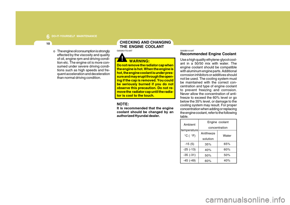
G050B01A-AAT Recommended Engine Coolant Use a high quality ethylene-glycol cool- ant in a 50/50 mix with water. Theengine coolant should be compatible with aluminum engine parts. Additional corrosion inhibitors or additives shouldnot be used. The cooling system must be maintained with the correct con- centration and type of engine coolantto prevent freezing and corrosion. Never allow the concentration of anti- freeze to exceed the 60% level or gobelow the 35% level, or damage to the cooling system may result. For proper concentration when adding or replacingthe engine coolant, refer to the following table.
Water
65% 60% 50% 40%
Antifreeze
solution 35% 40% 50%60%
Ambient
temperature
°C ( °F)
-15 (5)
-25 (-13)-35 (-31) -45 (-49) Engine coolant
concentration
!
CHECKING AND CHANGING THE ENGINE COOLANT
G050A01TG-AAT
WARNING:
Do not remove the radiator cap when the engine is hot. When the engine ishot, the engine coolant is under pres- sure and may erupt through the open- ing if the cap is removed. You couldbe seriously burned if you do not observe this precaution. Do not re- move the radiator cap until the radia-tor is cool to the touch. NOTE: It is recommended that the engine coolant should be changed by an authorized Hyundai dealer.
o The engine oil consumption is strongly
effected by the viscosity and qualityof oil, engine rpm and driving condi- tion etc. The engine oil is more con- sumed under severe driving condi-tions such as high speeds and fre- quent acceleration and deceleration than normal driving condition.
Page 237 of 282

6 DO-IT-YOURSELF MAINTENANCE
14
!
CAUTION:
o Radiator antifreeze (engine cool- ant) should not be used in the washer system because it will damage the car's finish.
o The washer should not be oper- ated if the washer reservoir isempty. This can damage thewasher fluid pump.!
WARNING:
o Windshield washer fluid agents contain some amounts of alcohol and can be flammable under cer- tain circumstances. Do not allow sparks or flame to contact thewasher fluid or the washer fluid reservoir. Damage to the vehicle or its occupants could occur.
o Windshield washer fluid is poi- sonous to humans and animals.Do not drink windshield washerfluid. Serious injury or death could occur.
CHECKING THE TRANSAXLE OIL (MANUAL)
G100A01MC-GAT
Transaxle lubricant in the manual transaxle should be checked at those intervals specified in the vehicle main-tenance schedule in Section 5.
!WARNING:
It is always better to check the transaxle oil level when the engine iscool or cold. If the engine is hot, you should exercise great caution to avoid burning yourself on hot en-gine or exhaust parts. NOTE: It is recommended that the manual transaxle fluid should be checked by an authorized Hyundai dealer.
FILLING THE WASHER RESERVOIR
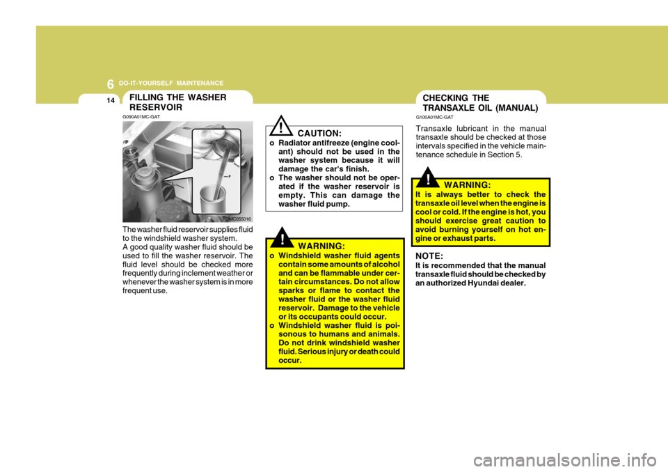
G090A01MC-GAT The washer fluid reservoir supplies fluid to the windshield washer system. A good quality washer fluid should be used to fill the washer reservoir. Thefluid level should be checked more frequently during inclement weather or whenever the washer system is in morefrequent use. OMC055016
Page 246 of 282

6
DO-IT-YOURSELF MAINTENANCE
23
G210B01Y-GAT Checking the Battery Keep the battery clean. Any evidence of corrosion around the battery postsor terminals should be removed using a solution of household baking soda and warm water. After the battery ter-minals are dry, cover them with a light coating of grease.
Keep batteries out of the reach of children because batteries contain highly cor- rosive SULFURIC ACID. Donot allow battery acid to con- tact your skin, eyes, cloth- ing or paint finish.If any electrolyte gets into your eyes, flush your eyes with clean water for at least15 minutes and get immedi- ate medical attention. If pos- sible, continue to applywater with a sponge or cloth until medical attention is re- ceived.If electrolyte gets on your skin, thoroughly wash the contacted area.If you feel a pain or a burn- ing sensation, get medical attention immediately.Wear eye protection when charging or working near a battery.Always provide ventilation when working in an en- closed space.
WARNING: Always read the following instructions carefully when handling a battery.Keep lighted cigarettes and all other flames or sparks away from the battery.Hydrogen, which is a highly combustible gas, is always present in battery cells andmay explode if ignited.!
o If battery fluid is on your skin, flush the affected areas with water for at least 15 minutes and then seek medi- cal assistance.
o If battery fluid is in your eyes, rinse
out your eyes with water and getmedical assistance as soon as pos- sible. While you are being driven toget medical assistance, continue to rinse your eyes by using a sponge or soft cloth saturated with water.
o If you swallow battery fluid, drink a large quantity of water or milk fol-lowed by milk of magnesia, eat araw egg or drink vegetable oil. Get medical assistance as soon as pos- sible.
While batteries are being charged (ei-ther by a battery charger or by thevehicle's alternator), they produce ex- plosive gases. Always observe these warnings to prevent injuries from oc-curring:
o Charge batteries only in a well ven- tilated area.
o Do not permit flames, sparks or
smoking in the area.
o Keep children away from the area.
Page 248 of 282

6
DO-IT-YOURSELF MAINTENANCE
25REMOVAL OF WATER FROM THE FUEL FILTER
1JBA7504
G240A01A-AAT POWER STEERING HOSES It is suggested that you check the power steering hose connections for fluid leakage at regular intervals. The power steering hoses should be re-placed if there is severe surface crack- ing, scuffing or worn spots. Deteriora- tion of the hose could cause prema-ture failure. G300A01MC-GAT (DIESEL ENGINE) If the fuel filter warning light illuminates during driving, it indicates that waterhas accumulated in the fuel filter. If this occurs, remove the water as soon as possible. NOTE: It is recommended that water accu- mulated in the fuel filter should be removed by an authorized Hyundaidealer.
NOTE:
o Grinding noise from the power
steering pump may be heard im- mediately after the engine is startedin extremely cold conditions (be- low - 20°C). If the noise stops during warm up, there is no ab-normal function in the system. It is due to a power steering fluid characteristic in extremely coldconditions.
o Do not start the engine when the
power steering oil reservoir isempty.
!WARNING:
Be sure to carefully wipe away any water drained out in this manner, because the fuel mixed in the watermight be ignited and result in a fire.
Page 249 of 282

6 DO-IT-YOURSELF MAINTENANCE
26HEADLIGHT AIMING ADJUSTMENT
5. Open the hood.
6. Draw the vertical line (through the
center of each headlight beam pat-tern) and the horizontal line (throughthe center of each headlight beam pattern) on the aiming screen. And then, draw a horizontal parallel line at 30 mm (1.18 in.) under the horizontal line.
7. Adjust each cut-off line of the low beam to the parallel line with a phillipsscrewdriver - VERTICAL AIMING.
8. Adjust each cut-off line of the low
beam to each vertical line with aphillips screwdriver - HORIZONTAL AIMING. Horizontal aiming
Vertical aiming
If the vehicle has had front body repair and the headlight assembly has beenreplaced, an headlight aiming should be checked using an aiming screen as shown in the illustration. Turn on theheadlight switch. (Low Beam Position)
1. Adjust headlights so that main axisof light is parallel to center line of the body and is aligned with point "P" shown in the illustration.
2. Dotted lines in the illustration show the center of headlights.
G290B01MC-GAT Adjustment After Headlight As- sembly Replacement
G290A03A-GAT Before performing aiming adjustment, make sure of the following.
1. Keep all tires inflated to the correct
pressure.
2. Place the vehicle on level ground
and press the front bumper and rear bumper down several times. Place the vehicle at a distance of 3,000 mm (118 in.) from the test wall.
3. See that the vehicle is unloaded (except for full levels of coolant,engine oil and fuel, and spare tire,jack, and tools). Have the driver or equivalent weight placed in driver's seat.
4. Clean the head lights lenses and turn on the headlight (low beam). G290B01B
LW
H
H Cut-off line
Ground line
"P"
Horizontal line
Vertical line30 mm
G290A03MC
Page 250 of 282

6
DO-IT-YOURSELF MAINTENANCE
27REPLACEMENT OF LIGHT BULBS
SPECIFICATIONS: "H" Horizontal center line of headlights from ground.: 665 mm (26.18 in.) "W" Distance between each headlight center. : 1,170 mm (46.06 in.) "L" Distance between the headlightsand the wall that the lights are tested against. : 3,000 mm (118.11 in.). G260A01MC-AAT Before attempting to replace a light bulb, be sure the switch is turned to the "OFF" position.The next paragraph shows how to reach the light bulbs so they may be changed. Be sure to replace the burned-out bulbwith one of the same number and watt- age rating. See page 6-34 for the wattage descrip-tions.
CAUTION:
o Keep the lamps out of contact with petroleum products, such as oil,gasoline, etc.
o If you don't have necessary tools,
the correct bulbs and the exper-tise, consult your authorized Hyundai dealer.
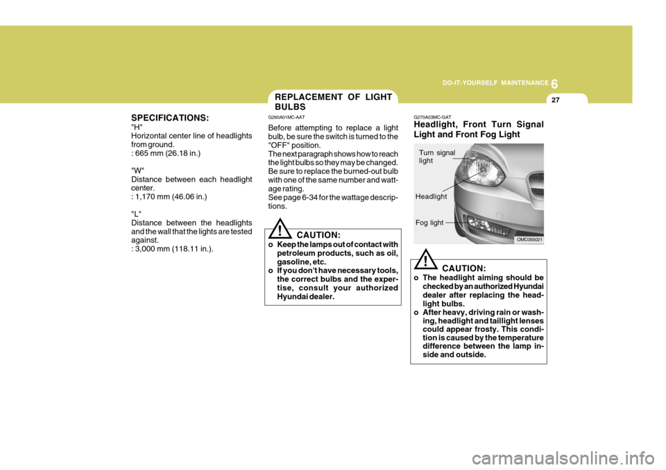
! G270A03MC-GAT Headlight, Front Turn Signal Light and Front Fog Light
CAUTION:
o The headlight aiming should be checked by an authorized Hyundai dealer after replacing the head- light bulbs.
o After heavy, driving rain or wash- ing, headlight and taillight lenses could appear frosty. This condi-tion is caused by the temperaturedifference between the lamp in-side and outside.
!
OMC055021
Turn signal light
Headlight Fog light
Page 258 of 282

6
DO-IT-YOURSELF MAINTENANCE
35
FUSE RATING 125A50A 40A 40A 40A40A 30A 30A30A 30A 30A20A 15A10A 10A 10A10A 10A30A 80A
G200C01MC-GAT Engine Compartment (Gasoline Engine)
G200C01MC
NOTE:
Not all fuse panel descriptions in this manual may be applicable to your vehicle. It is accurate at the time of printing.
When you inspect the fuse box on your vehicle, refer to the fuse box label. CIRCUIT PROTECTED
Generator I/P Junction Box
Blower Relay, Blower MotorABS Control Module, ESP Module, Multipurpose Check Connector ABS Control Module, ESP Module, Multipurpose Check Connector
Start Relay, Ignition SwitchIgnition Switch I/P Junction Box I/P Junction BoxCondenser Fan Relay #1, RAD Fan Relay
Main Relay, Fuel Pump Relay ECM, PCM
Injector #1, #2, #3, #4, CVVT Oil Control Valve, Immobilizer Control Module,Purge
Control Solenoid Valve, Idle Speed Control Actuator A/Con RelayA/C Control ModuleECM, TCM, PCM
Horn Relay, Burglar Alarm Horn Relay
A/Con Relay, Rad Fan Relay, Condenser Fan Relay #1, #2, Camshaft Position
Sensor,Oxygen Sensor(UP, DOWN), Mass Air Flow Sensor Condenser Fan Relay #1 EPS Control Module
MAIN
BATT #1
BLOWER
ABS #1 ABS #2IGN #2 IGN #1
BATT #2 P/WDW
RAD
ECU A ECU C
INJ
A/CON #1 A/CON #2 ECU BHORN
SNSR
COND
M.D.P.S
FUSE
FUSE PANEL DESCRIPTION
Page 261 of 282

6 DO-IT-YOURSELF MAINTENANCE
38
FUSE RATING10A 20A10A 10A 15A 10A10A 20A 10A 15A 10A 15A 10A10A 10A 10A 10A CIRCUIT PROTECTED
Front Fog Lamp Switch, Front Fog Lamp LH, Front Fog Lamp RH,BCM Sunroof Motor Hazard SwitchOver Driver Switch, TCM(Diesel), Pulse Generator 'A'(Diesel),Pulse Generator
'B'(Diesel), Vehicle Speed Sensor
Data Link Connector, Stop Lamp Switch, P/WDW Relay,Multipurpose CheckConnector Instrument Cluster ECM, PCM, EPS Control Module, Mass Air Flow Sensor(Diesel), Fuel FilterWarning Switch(Diesel) Driver Door Lock Actuator, Assist Door Lock Actuator, BCM,Rear Door Lock
Actuator LH, Rear Door Lock Actuator RH,Driver Power Window Switch, TailGate Lock Actuator Start Relay BCM, Instrument Cluster, Generator, DRL Control ModuleIgnition Coil #1, #2, #3, #4, CondenserAudio
Luggage Lamp, Room Lamp, Vanity Lamp Switch, Digital Clock,Overhead Consol Lamp, A/C Control Module, Instrument Cluster,Back Warning Buzzer, Door Warning Switch, BCM ESP Switch, Steering Angle Sensor, ABS Control Module,ESP Module,Multipurpose Check Connector
Back-up Lamp Switch, Transaxle Range Switch DRL Control ModulePower Outside Mirror & Mirror Folding Switch
FR FOG LP S/ROOF
T/SIG LP
TCU
STOP LP
A/BAG IND ECU
C/DR LOCK START
CLUSTER IGN COIL AUDIO
(Power Connector)
MULT B/UP
(Power Connector)
ABS
B/UP LP DRL
FOLD'G
FUSE