Page 15 of 28

Secure the winch hook. While keeping the line near the ground, insert
the winch hook through the clevis/D-shackle. Check the anchor. Make
sure all connections are secured and free of debris before continuing
with the winching procedure.
Maintenance
²Inspect the wire rope before and after each winching operation. If the
wire rope has become kinked or frayed, it needs to be replaced. Be
sure to also inspect the winch hook and hook pin for signs of wear or
damage. Replace as necessary.
²Keep winch, wire rope and switch control free from contaminants. Use
a clean rag or towel to remove any dirt and debris. If necessary,
unwind the winch completely (leaving a minimum of five wraps of
rope on the drum) and wipe it clean before rewinding it. Using a light
oil on the rope and winch hook can keep rust and corrosion from
forming.
²Operating the winch for an extended period of time places an
additional load on your vehicle battery. Be sure to check and maintain
your battery and battery cables according to manufacturer guidelines.
Also, inspect the switch control and all electrical connections to be
certain they are clean and tight fitting.
²Inspect the remote control, if so equipped, for damage. Be sure to cap
the remote socket to prevent dirt and debris from entering the
connections. Store the remote control in a dry, protected area.
²No lubrication is required for the life of the winch.
Driver Controls
15
Page 23 of 28

is located underneath the truck, by the forward stake pocket on the left
side of the bed. If operating the air system in dusty areas, periodically
inspect this filter and replace it if found to be clogged or damaged, or if
the time needed to pressurize the system starts to become extended.
Using the air system to fill tires
To fill your tires, first be sure to stop the truck in a safe place. You
should be far enough off the road that passing traffic will not be a danger
to you. You should have an accurate tire pressure gauge to measure the
pressure in the tires and inflate them to the settings on the tire pressure
placard, which is usually inside the door on the truck.
Remove the air hose from under the clamp on the floor of the truck.
Attach the connector end of the hose to the coupling in the trim panel
behind the driver's seat by using one hand to slide the coupling collar
toward the trim panel and the other to insert the fitting on the end of
the hose into the coupling. When the fitting is seated in the coupling,
slide the collar back to its original position.
Extend the hose to reach the tire needing air. Remove the cap from the
tire valve stem and attach the clamp-on air chuck by squeezing the
locking mechanism while placing the chuck over the valve stem. Release
the locking mechanism when the air chuck is seated on the stem. Air will
flow from the system to the tire until you remove the chuck. Be sure to
use your gauge to set the pressure according to the placard. When the
tire pressure is correct, disconnect the hose and re-stow it under the
clamp on the floor behind the passenger seat. Do not forget to re-install
the cap on the valve stem.
CENTRAL TIRE INFLATION SYSTEM (CTIS) (IF EQUIPPED)
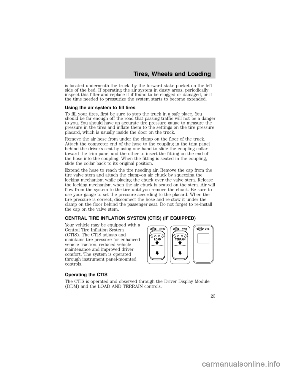
Your vehicle may be equipped with a
Central Tire Inflation System
(CTIS). The CTIS adjusts and
maintains tire pressure for enhanced
vehicle traction, reduced vehicle
maintenance and improved driver
comfort. The system is operated
through instrument panel-mounted
controls.
Operating the CTIS
The CTIS is operated and observed through the Driver Display Module
(DDM) and the LOAD AND TERRAIN controls.
Tires, Wheels and Loading
23
Page 24 of 28

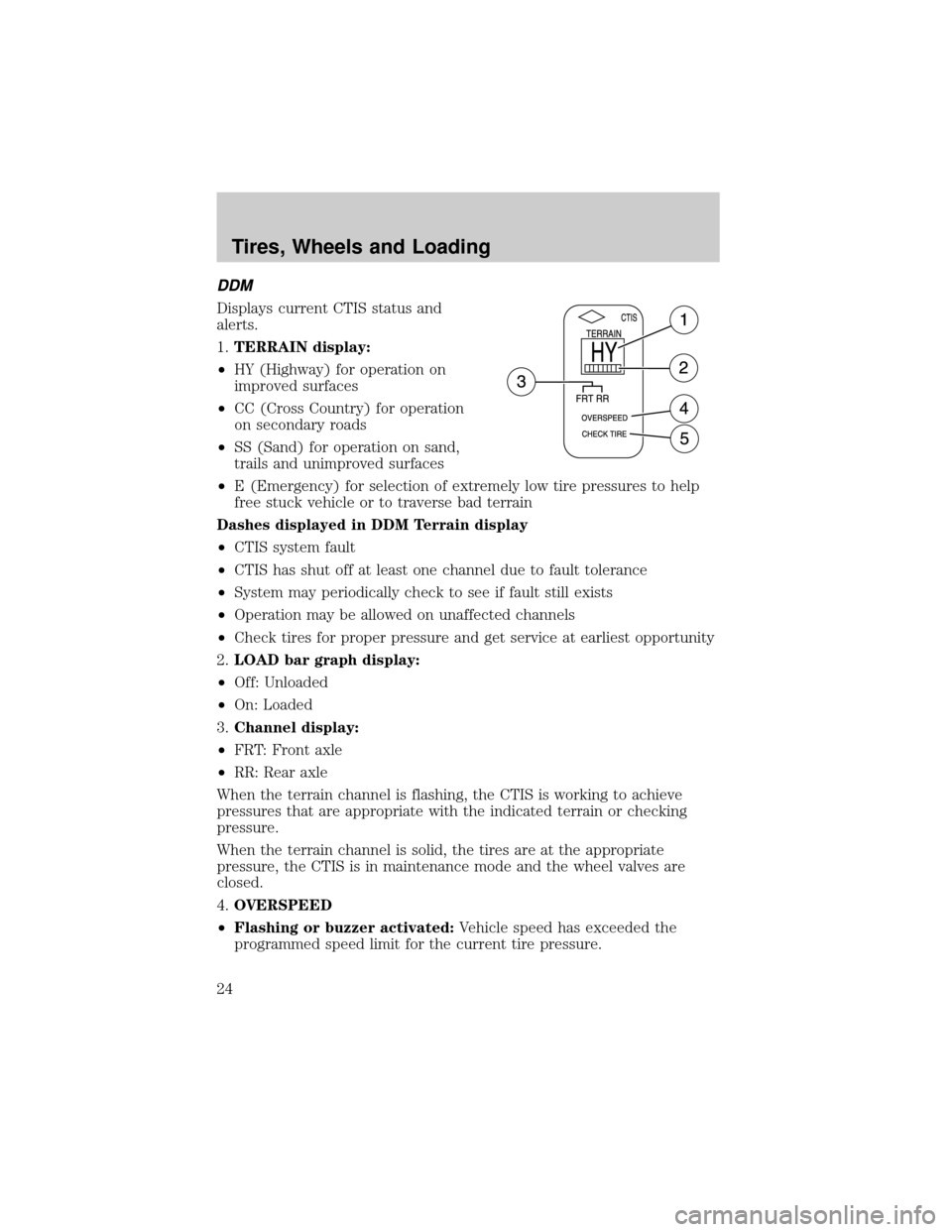
DDM
Displays current CTIS status and
alerts.
1.TERRAIN display:
²HY (Highway) for operation on
improved surfaces
²CC (Cross Country) for operation
on secondary roads
²SS (Sand) for operation on sand,
trails and unimproved surfaces
²E (Emergency) for selection of extremely low tire pressures to help
free stuck vehicle or to traverse bad terrain
Dashes displayed in DDM Terrain display
²CTIS system fault
²CTIS has shut off at least one channel due to fault tolerance
²System may periodically check to see if fault still exists
²Operation may be allowed on unaffected channels
²Check tires for proper pressure and get service at earliest opportunity
2.LOAD bar graph display:
²Off: Unloaded
²On: Loaded
3.Channel display:
²FRT: Front axle
²RR: Rear axle
When the terrain channel is flashing, the CTIS is working to achieve
pressures that are appropriate with the indicated terrain or checking
pressure.
When the terrain channel is solid, the tires are at the appropriate
pressure, the CTIS is in maintenance mode and the wheel valves are
closed.
4.OVERSPEED
²Flashing or buzzer activated:Vehicle speed has exceeded the
programmed speed limit for the current tire pressure.
Tires, Wheels and Loading
24
Page 27 of 28

Tire pressure maintenance
The CTIS is set to check tire pressure every 15 minutes. The wheel
valves will automatically isolate the tires from the rest of the system; this
prevents a decrease in tire pressure due to fitting and seal leaks.
Some clicking may be heard as the system activates to achieve a new tire
pressure. Adequate supply system air pressure is required to begin or
continue any pressure change.
The system is designed to allow tire pressure increases due to heat
build-up during vehicle use. The system will not deflate the pressure
build-ups, a lower pressure mode selection must be made to decrease
the tire pressure.
Flat tire/Tire leak detection
If the CTIS detects a significantly low tire, the system will display a
ªCHECK TIREº message, sound a buzzer and automatically attempt to
inflate the tire(s) to the selected mode pressure. The ªCHECK TIREº
message and buzzer will stay on until the tire is inflated to the selected
mode pressure.
Tires, Wheels and Loading
27