Page 1076 of 1226

308-01 4 Clutch 308-01 -4
DESCRIPTION AND OPERATION
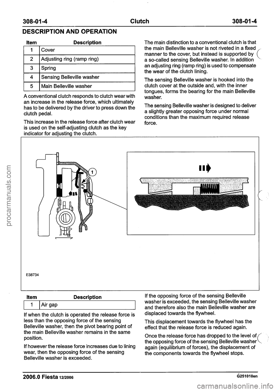
Item Description
I I 1 Cover I
1 2 I Adjusting ring (ramp ring) I
1 3 1 Spring I
1 4 1 Sensing Belleville washer I
r5 1 Main Belleville washer I
A conventional clutch responds to clutch wear with
an increase in the release force, which ultimately
has to be delivered by the driver to press down the
clutch pedal.
This increase in the release force after clutch wear
is used on the self-adjusting clutch as the key
indicator for adjusting the clutch. The main
distinction to a conventional clutch is that
the main Belleville washer is not riveted in a fixed
-
manner to the cover, but instead is supported by (
a so-called sensing Belleville washer. In addition
an adjusting ring (ramp ring) is used to compensate
the wear of the clutch lining.
The sensing Belleville washer is hooked into the
clutch cover at the outside and, with the inner
tongues, forms the bearing for the main Belleville
washer.
The sensing Belleville washer is designed to deliver
a slightly greater opposing force under normal
conditions than the maximum required release
force.
Item Description
If when the clutch is operated the release force is
less than the opposing force of the sensing
Belleville washer, then the pivot bearing point of
the main Belleville washer remains in the same
position.
If however the release force increases due to lining
wear, then the opposing force of the sensing
Belleville washer is exceeded. If the
opposing force of the sensing Belleville
washer is exceeded, the sensing Belleville washer
and therefore also the main Belleville washer are
displaced towards the flywheel.
This displacement towards the flywheel has the
effect that the release force is reduced again.
Once the release force has dropped to the level of
the opposing force of the sensing Belleville washer
again (equilibrium of forces), the displacement of
the components towards the flywheel stops.
2006.0 Fiesta lazoos ~251010en
procarmanuals.com
Page 1144 of 1226

308-03-54 Manual Transmission/Transaxle 308-0344
ASSEMBLY
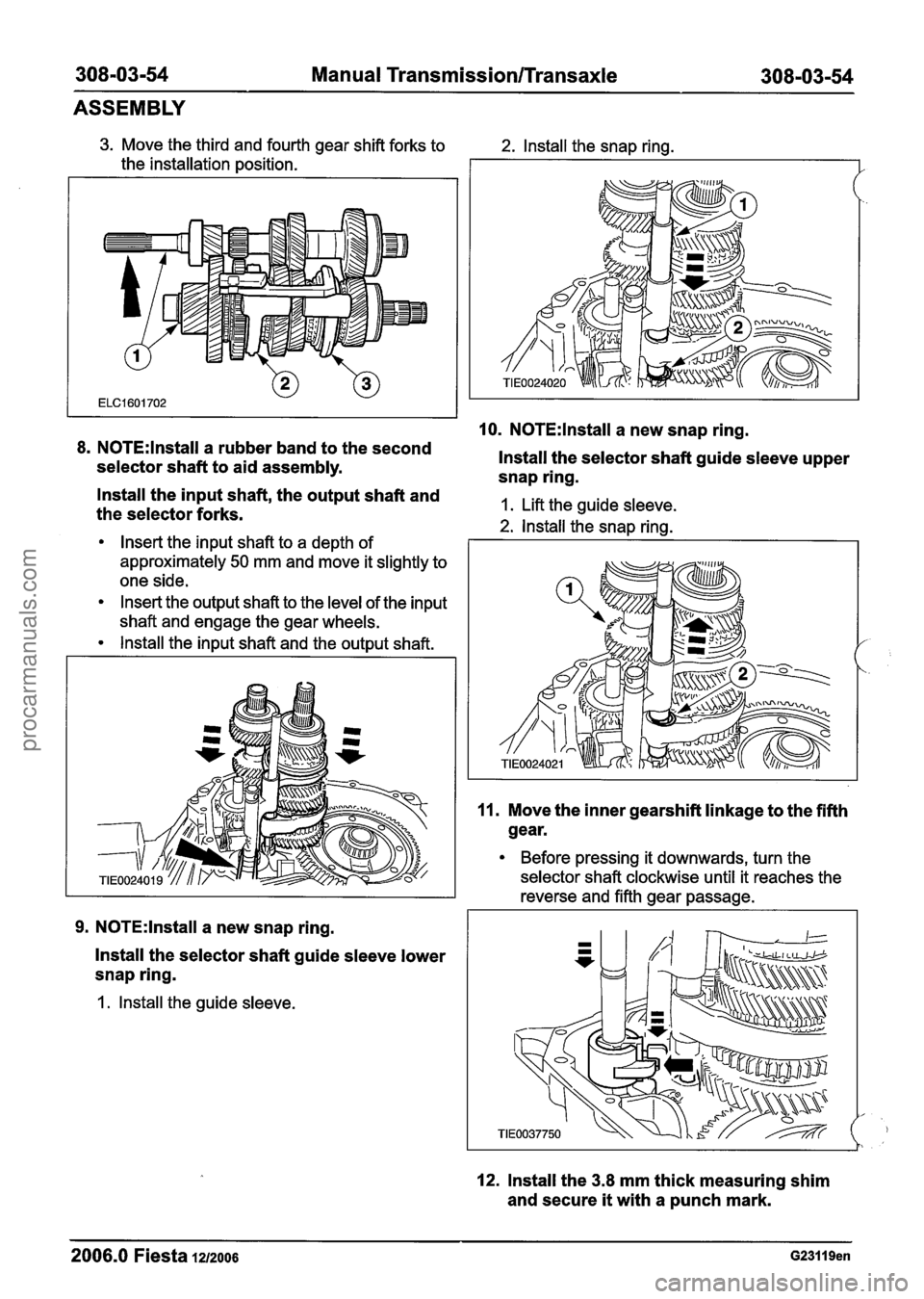
3. Move the third and fourth gear shift forks to
the installation position.
8. N0TE:lnstall a rubber band to the second
selector shaft to aid assembly.
2. lnstall the snap ring.
10. N0TE:lnstall a new snap ring.
lnstall the selector shaft guide sleeve upper
snap ring.
- lnstall the input shaft, the output shaft and
the selector forks. 1. Lift the guide sleeve.
2. lnstall the snap rina.
Insert the input shaft to a depth of I
approximately 50 mm and move it slightly to
one side.
Insert the output shaft to the level of the input
shaft and engage the gear wheels.
lnstall the input shaft and the output shaft.
9. N0TE:lnstall a new snap ring.
lnstall the selector shaft guide sleeve lower
snap ring.
1. lnstall the guide sleeve.
11. Move the inner gearshift linkage to the fifth
gear.
Before pressing it downwards, turn the
selector shaft clockwise until it reaches the
reverse and fifth gear passage.
12. lnstall the 3.8 mm thick measuring shim
and secure
it with a punch mark.
2006.0 Fiesta 1212006 G23119en
procarmanuals.com
Page 1147 of 1226
308-03-57 Manual Transmission/Transaxle 308-03-57 I I
ASSEMBLY
21. Apply sealer on the inside edge of the Install
the fifth gear housing gasket.
1. transaxle housing mating face.
22. Assemble the transaxle housing and tighten 26m ACAUTION:M~~~ sure the snap rings are
in the correct position. Failure to follow this
the bolts.
instruction may cause damage to the fifth
23. N0TE:lnstall new input and output shaft
snap rings. gear
housing.
Turn the snap rings to the position shown.
Raise the and shafts 'lightly 27. NOTE:lnstall new fifth gear housing
and install the snap rings.
retaining bolts.
' 24. Using a suitable thread die, clean all the Install
the fifth gear housing.
-I hole threads in the fifth gear housing.
25. N0TE:lnstall a new fifth gear housing 28. Remove the transaxle from the mounting
stand.
gasket.
2006.0 Fiesta 1212006 G23119en
procarmanuals.com
Page 1171 of 1226
Manual Transmission/Transaxle External
Controls
REMOVAL AND INSTALLATION
Gearshift Lever(l6 524 0)
Removal
I. Remove the gearshift lever trim panel.
Disconnect the cigar lighter electrical
connector.
2. Detach the gearshift cables from the
gearshift lever.
4. Remove the gearshift lever front retaining
bolts.
5. Remove the gearshift lever.
Remove the bolts.
Installation
1. To install, reverse the removal procedure. 3. Detach the gearshift cables from the
retaining bracket. 2. Adjust the gearshift cables. For additional
information, refer to Section
308-00 [Manual Turn the abutment sleeves clockwise. Transmission/Transaxle and Clutch - General
Information].
2006.0 Fiesta 1212006 GI 86744en
procarmanuals.com
Page 1189 of 1226
31 0-00-3 Fuel System - General Information 31 0-00-3
GENERAL PROCEDURES
/'
Fuel System Pressure Release(23 420 0)
i
Release
I. WARNINGS:
ADO not smoke or carry lighted tobacco or
open flame of any type when working on or
near any fuel related components. Highly
flammable vapors are always present and
may ignite. Failure to follow these
instructions may result in personal injury.
A~he fuel system remains pressurized for
a long time after the ignition is switched off.
The fuel pressure must be released before
attempting any repairs. Failure to follow this
instruction may result in personal injury.
Remove the fuel pump fuse.
2. Start the engine and allow to idle until the
engine stalls.
3. Crank the engine for approximately five
seconds to make sure the fuel injection
supply manifold pressure has been released.
,1 4. Install the fuel pump fuse.
2006.0 Fiesta 1212006 GI 81 91 en
procarmanuals.com
Page 1190 of 1226
31 0-00-4 Fuel System - General Information 31 0-00-4
GENERAL PROCEDURES
Fuel Tank Draining(23 551 0)
General Eaui~ment
I Fuel tank draining equipment I
Draining
WARNINGS:
A Do not smoke or carry lighted tobacco or
open flame of any type when working on
or near any fuel related components.
Highly flammable vapors are always
present and may ignite. Failure to follow
these instructions may result in personal
injury.
A The fuel system remains pressurized for a
long time after the ignition is switched off.
The fuel pressure must be relieved before
attempting any repairs. Failure to follow
these instructions may result in personal
injury.
I. Disconnect the battery ground cable. For
additional information, refer to
Section
414-01 [Battery, Mounting and
Cables].
2. Remove the fuel tank filler cap.
3. Using fuel tank draining equipment, drain
the fuel from the fuel tank using a
12.5mm
nylon drain tube.
2006.0 Fiesta 1212006 G210056en
procarmanuals.com
Page 1191 of 1226

31 0-00-5 Fuel System - General Information 31 0-00-5
GENERAL PROCEDURES
Quick Release Coupling
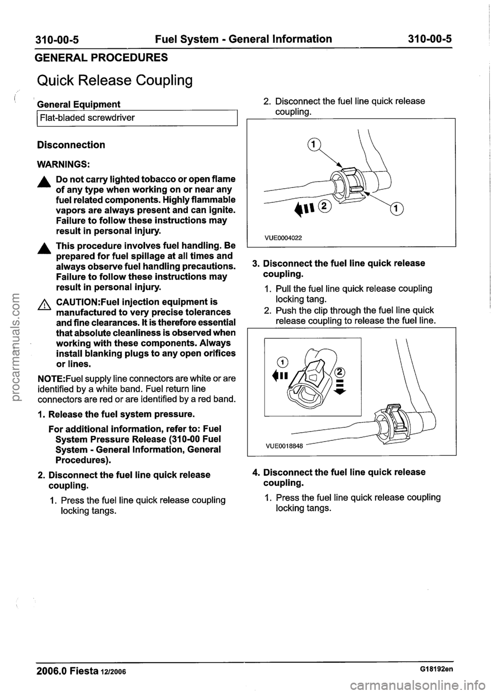
i 1 General Equipment 2. Disconnect the fuel line quick release
coupling.
Flat-bladed screwdriver
Disconnection
WARNINGS:
A Do not carry lighted tobacco or open flame
of any type when working on or near any
fuel related components. Highly flammable
vapors are always present and can ignite.
Failure to follow these instructions may
result in personal injury.
A This procedure involves fuel handling. Be
prepared for fuel spillage at all times and
always observe fuel handling precautions.
Failure to follow these instructions may
result in personal injury. 3.
Disconnect the fuel line quick release
coupling.
1. Pull the fuel line quick release coupling
CAUTI0N:Fuel injection equipment is locking tang.
manufactured to very precise tolerances 2. Push the clip through the fuel line quick
and fine clearances. It is therefore essential release coupling to release the fuel line.
that absolute cleanliness is observed when I
i
working with these components. Always
install blanking plugs to any open orifices
or lines.
N0TE:Fuel supply line connectors are white or are
identified by a white band. Fuel return line
connectors are red or are identified by a red band.
1. Release the fuel system pressure.
For additional information, refer to: Fuel
System Pressure Release (31
0-00 Fuel
Svstem - General Information, General
2. Disconnect the fuel line quick release 4. Disconnect the fuel line quick release
coupling. coupling.
1. Press the fuel line quick release coupling 1. Press the fuel line quick release coupling
locking tangs. locking tangs.
2006.0 Fiesta 1212006 GI 81 92en
procarmanuals.com
Page 1193 of 1226

31 0-00-7 Fuel System - General Information 31 0-00-7
GENERAL PROCEDURES
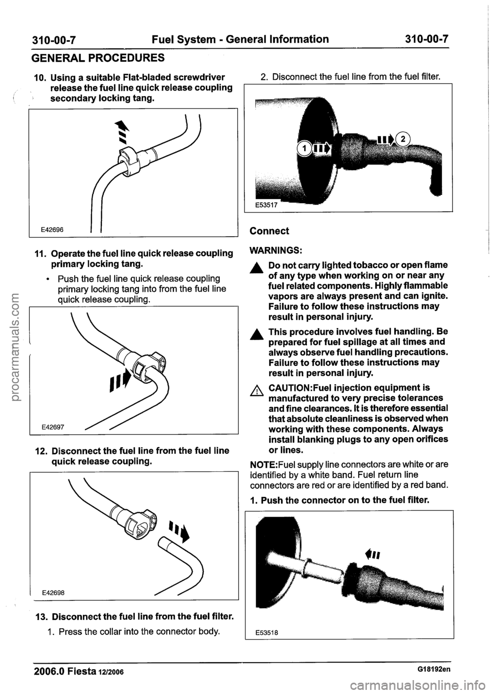
10. Using a suitable Flat-bladed screwdriver 2. Disconnect the fuel line from the fuel filter.
release the fuel line quick release coupling
( secondary locking tang.
Connect
11. Operate the fuel line quick release coupling WARNINGS:
primary locking tang.
Push the fuel line quick release coupling
primary locking tang into from the fuel line
quick release coupling.
12. Disconnect the fuel line from the fuel line
quick release coupling.
13. Disconnect the fuel line from the fuel filter.
1 . Press the collar into the connector body.
Do not carry lighted tobacco or open flame
of any type when working on or near any
fuel related components. Highly flammable
vapors are always present and can ignite.
Failure to follow these instructions may
result in personal injury.
A This procedure involves fuel handling. Be
prepared for fuel spillage at all times and
always observe fuel handling precautions.
Failure to follow these instructions may
result in personal injury.
A CAUTI0N:Fuel injection equipment is
manufactured to very precise tolerances
and fine clearances.
It is therefore essential
that absolute cleanliness is observed when
working with these components. Always
install blanking plugs to any open orifices
or lines.
N0TE:Fuel supply line connectors are white or are
identified by a white band. Fuel return line
connectors are red or are identified by a red band.
1. Push the connector on to the fuel filter.
2006.0 Fiesta 1212006 GI 81 92en
procarmanuals.com