Page 835 of 1226

Fuel Charging and Controls - 2.OL
303-04B-27 Duratec-HE (M14) 303-04B-27
REMOVAL AND INSTALLATION
Fuel Rail
Materials Name Specification
I Engine Oil - 5W-30 I WSS-~2~91 3-B I
WARNINGS:
A Do not smoke or carry lighted tobacco or
open flame of any type when working on
or near any fuel related components.
Highly flammable vapors are always
present and may ignite. Failure to follow
these instructions may result in personal
injury.
A This procedure involves fuel handling. Be
prepared for fuel spillage at all times and
always observe fuel handling precautions.
Failure to follow these instructions may
result in personal injury.
1. Release the fuel system pressure.
For additional information, refer to: Fuel
System Pressure Release (31 0-00 Fuel
System
- General Information, General
Procedures).
2. Disconnect the battery ground cable.
For additional information, refer to: Battery
Disconnect
(414-01 Battery, Mounting and
Cables, General Procedures).
3. Remove the air cleaner assembly.
For additional information, refer to: Air
Cleaner
- 2.OL Duratec-HE (M14) (303-1 2
intake Air Distribution and Filtering,
Removal and Installation).
4. Remove the components in the order
indicated in the following
illustration(s) and
table(s).
Item Description Item Description
Fuel charging wiring harness retaining clip
See Removal Detail
Fuel charging wiring harness electrical
connector
2006.0 Fiesta 1212006 G421322en
procarmanuals.com
Page 912 of 1226

303-1 2-8 Intake Air Distribution and Filtering 303-1 2-8
DIAGNOSIS AND TESTING
Svm~tom Possible Sources Action
Oil in the air intake system Blocked or damaged positive
crankcase
ventilation (PCV)
valve.
Blocked or damaged PCV
pipe(s)/hose(s).
Blocked or damaged crankcase
vent
oil separator.
Vehicles with 1.25L Duratec-
16V
(Sigma)/l.3L Duratec-8V (
(Rocam)/l.4L Duratec-I 6V
(Sigma)/l .6L Duratec-1 6V
(Sigma) engine.
REFER to: Crankcase Vent
Oil
Separator (303-08 Engine
Emission
Control - 1.3L
Duratec-8V (Rocam)/l.25L
Duratec-I 6V (Sigma)/l.4L
Duratec-I 6V (Sigma)/l .6L
Duratec-1
6V (Sigma),
Removal and Installation).
Vehicles with 2.0L Duratec-HE
(M14) engine.
REFER to: Crankcase Vent
Oil
Separator (303-08C Engine
Emission
Control - 2.OL
Duratec-HE (M14), Removal
and Installation).
Turbocharger (Vehicles with
Duratorq-TDCi (DV)
Diesel
engine or 1.6L Duratorq-TDCi
(DV)
Diesel engine).
Vehicles with 1.4L Duratorq-
TDCi (DV)
Diesel engine.
REFER to: Turbocharger (303- 04
Fuel Charging and
Controls - Turbocharger -
1.4L Duratorq-TDCi (DV)
Diesel, Removal and Installa-
tion).
Vehicles with I .6L Duratorq-
TDCi (DV)
Diesel engine.
REFER to: Turbocharger
- I .6L
Duratorq-TDCi (DV)
Diesel
(303-04 Fuel Charging and
Controls - Turbocharger -
1.6L Duratorq-TDCi (DV)
Diesel, Removal and Installa-
tion).
Water in the air cleaner Detached air cleaner intake
pipe. CHECK
the air cleaner intake
pipe for security. INSTALL new
intake air system components
as necessary. TEST the
system for
normal operation.
Blocked air cleaner drain. CLEAN
the air cleaner drain.
TEST the system for
normal
operation.
Engine lacks power
Air cleaner element blocked. INSPECT the air cleaner for ,.
new air cleaner element as
i signs of blockage. INSTALL a .
necessary. I_
2006.0 Fiesta 1212006 G421937en
procarmanuals.com
Page 914 of 1226

303-1 2-1 0 Intake Air Distribution and Filtering 303-1 2-1 0
DIAGNOSIS AND TESTING
Symptom
Possible Sources Action
2006.0 Fiesta 1212006 G421937en
Fuel charging and controls Vehicles with 1.3L Duratec-8
(Rocam) engine.
REFER to:
Fuel Charging and
Controls (303-04 Fuel Char-
ging and
Controls - 1.3L
Duratec-8V (Rocam),
Diagnosis and Testing).
Vehicles with 1.25L Duratec-
16V (Sigma)/l.4L Duratec-1 6V
(Sigma)/l .6L Duratec-I 6V
(Sigma) engine.
REFER to:
Fuel Charging and
Controls (303-04 Fuel Char-
ging and
Controls - 1.25L
Duratec-1 6V (Sigma)/l.4L
Duratec-1 6V (Sigma)/l .6L
Duratec-I
6V (Sigma),
Diagnosis and Testing).
Vehicles with I .4L Duratorq-
TDCi (DV)
Diesel engine.
REFER to:
Fuel Charging and
Controls (303-04 Fuel Char-
ging and
Controls - 1.4L
Duratorq-TDCi (DV) Diesel,
Diagnosis and Testing).
Vehicles with 2.OL Duratec-HE
(M14) engine.
REFER to:
Fuel Charging and
Controls (303-04 Fuel Char-
ging and
Controls - 2.OL
Duratec-H E (M14), Diagnosis
and Testing).
Vehicles with I .6L Duratorq-
TDCi (DV)
Diesel engine.
REFER to:
Fuel Charging and
Controls (303-04 Fuel Char-
ging and
Controls - 1.6L
Duratorq-TDCi (DV) Diesel,
Diagnosis and Testing).
procarmanuals.com
Page 915 of 1226
303-1 2-1 1 Intake Air Distribution and Filtering 303-1 2-1 I
DIAGNOSIS AND TESTING
Symptom Possible Sources Action
Turbocharger (Vehicles
with
Duratorq-TDCi (DV) Diesel
engine or
1.6L Duratorq-TDCi
(DV) Diesel engine). Vehicles
with
1.4L Duratorq-
TDCi (DV) Diesel engine.
REFER to: Turbocharger (303-
04 Fuel Charging and
Controls
- Turbocharger -
1.4L Duratorq-TDCi (DV)
Diesel, Removal and Installa-
tion).
Vehicles with
1.6L Duratorq-
TDCi (DV) Diesel engine.
REFER to: Turbocharger
- 1.6L
Duratorq-TDCi (DV) Diesel
(303-04 Fuel Charging and
Controls
- Turbocharger -
1.6L Duratorq-TDCi (DV)
Diesel, Removal and Installa-
tion).
2006.0 Fiesta 1212006 G421937en
procarmanuals.com
Page 954 of 1226
303-1 4-30 Electronic Engine Controls 303-1 4-30
REMOVAL AND INSTALLATION
Heated Oxygen Sensor (H02S)(29 220 0) /
Removal
Special Tool(s) 4. Disconnect the H02S electrical connector. (. .. >k,
1. Remove the air cleaner. For additional
information, refer to Section 303-1 2 [Intake
Air Distribution and Filtering].
5. Remove the exhaust manifold heat shield.
2. Disconnect the ignition coil pack electrical
connector.
23050
3. Detach the ignition coil pack and position it
to one side
Socket, Fuel Injector (22mm)
31 0-063 (23-050)
6. Using the special tool, remove the H02S.
Installation
A CAUTI0N:When installing a new H02S, it
is possible that the new component will be (- supplied with a longer cable than the one ,
removed. It is important that the cable is
routed and secured in such a way that
it
2006.0 Fiesta 1212006 G210054en
procarmanuals.com
Page 1188 of 1226
31 0-00-2 Fuel System - General Information 31 0-00-2
DIAGNOSIS AND TESTING
Fuel System - 1.3L Duratec-8V (Rocam)/l.25L Duratec-1 6V
(Sigma)/2.0L Duratec-HE (M14)/1.4L Duratec-I 6V
(Sigma)/l.GL Duratec-1 6V (Sigma)
lnspection and Verification
1. Verify the customer concern.
2. Visually inspect for obvious signs of mechanical
or electrical damage.
- Fuel level
- Fuel leak(s)
- Fuel line(s)
- Fuel filter (if
equipped)
- Fuel tank
- Fuel tank filler pipe
- Fuel filler cap
Visual lnspection Chart
- Electrical
connector(s)
- Wiring harness
- Inertia fuel shutoff
(IFS) switch
- Fuel pump module
I Mechanical
3. If an obvious cause for an observed or reported
concern is found, correct the cause (if possible)
before proceeding to the next step
4. If the cause is not visually evident, verify the
symptom and refer to WDS.
Electrical
-
2006.0 Fiesta 1212006 G348253en
procarmanuals.com
Page 1193 of 1226

31 0-00-7 Fuel System - General Information 31 0-00-7
GENERAL PROCEDURES
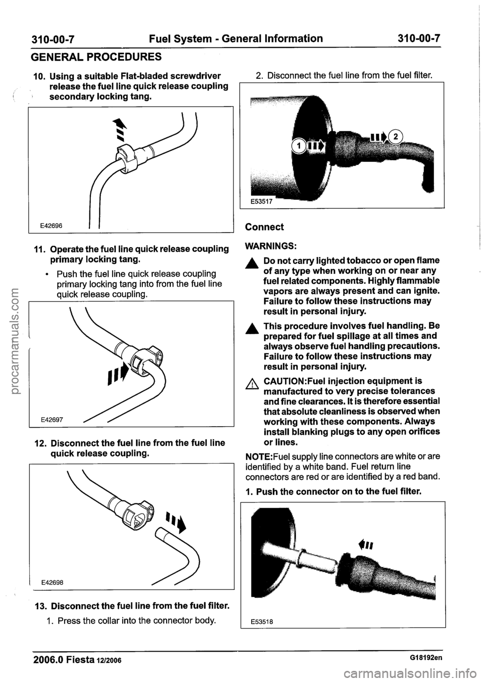
10. Using a suitable Flat-bladed screwdriver 2. Disconnect the fuel line from the fuel filter.
release the fuel line quick release coupling
( secondary locking tang.
Connect
11. Operate the fuel line quick release coupling WARNINGS:
primary locking tang.
Push the fuel line quick release coupling
primary locking tang into from the fuel line
quick release coupling.
12. Disconnect the fuel line from the fuel line
quick release coupling.
13. Disconnect the fuel line from the fuel filter.
1 . Press the collar into the connector body.
Do not carry lighted tobacco or open flame
of any type when working on or near any
fuel related components. Highly flammable
vapors are always present and can ignite.
Failure to follow these instructions may
result in personal injury.
A This procedure involves fuel handling. Be
prepared for fuel spillage at all times and
always observe fuel handling precautions.
Failure to follow these instructions may
result in personal injury.
A CAUTI0N:Fuel injection equipment is
manufactured to very precise tolerances
and fine clearances.
It is therefore essential
that absolute cleanliness is observed when
working with these components. Always
install blanking plugs to any open orifices
or lines.
N0TE:Fuel supply line connectors are white or are
identified by a white band. Fuel return line
connectors are red or are identified by a red band.
1. Push the connector on to the fuel filter.
2006.0 Fiesta 1212006 GI 81 92en
procarmanuals.com
Page 1196 of 1226

31 0-00-1 0 Fuel System - General Information 31 0-00-1 0
GENERALPROCEDURES
Fuel System Pressure Check - 2.OL Duratec-HE (M14)
Special Tool(s)
I Test Hose for 31 0-025
I I Test Hose for 31 0-025 1
General Equipment 1
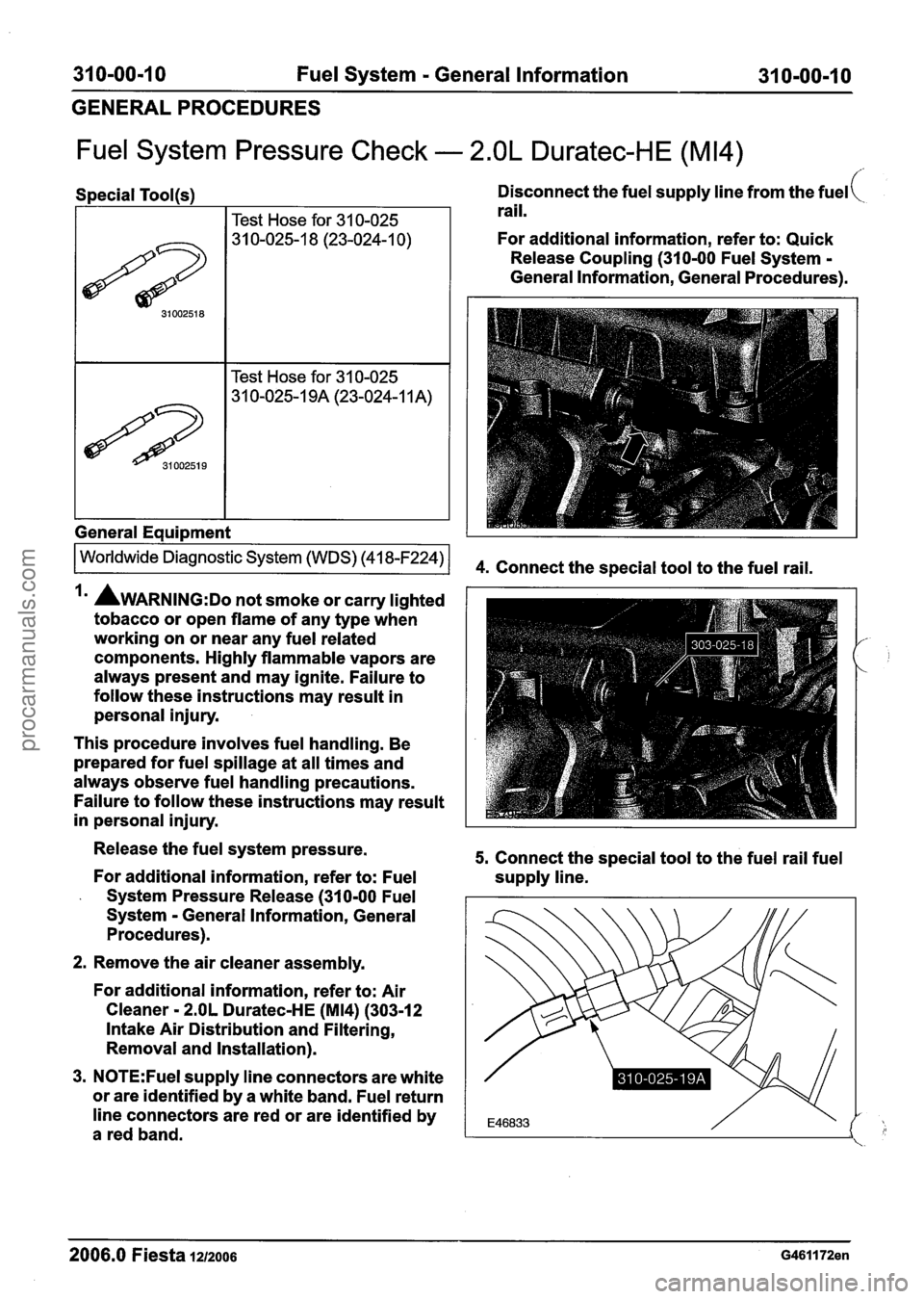
Disconnect the fuel supply line from the fuel(
rail.
For additional information, refer to: Quick
Release Coupling (310-00 Fuel System
-
General Information, General Procedures).
Irn AWARNING:D~ not smoke or carry lighted
tobacco or open flame of any type when
working on or near any fuel related
components. Highly flammable vapors are
always present and may ignite. Failure to
follow these instructions may result in
personal injury.
This procedure involves fuel handling. Be
prepared for fuel spillage at all times and
always observe fuel handling precautions.
Failure to follow these instructions may result
in personal injury.
Release the fuel system pressure.
For additional information, refer to: Fuel
- System Pressure Release (310-00 Fuel
System
- General Information, General
Procedures).
2. Remove the air cleaner assembly.
For additional information, refer to: Air
Cleaner
- 2.OL Duratec-HE (M14) (303-12
Intake Air Distribution and Filtering,
Removal and Installation).
3.
N0TE:Fuel supply line connectors are white
or are identified by a white band. Fuel return
line connectors are red or are identified by
a red band.
5. Connect the special tool to the fuel rail fuel
supply line.
- - -- - - -
2006.0 Fiesta 1212006 G461172en
procarmanuals.com