2007 FORD FIESTA tire pressure
[x] Cancel search: tire pressurePage 336 of 1226

21 1-00-1 6 Steering System - General Information 21 I -00-1 6
DIAGNOSIS AND TESTING
8m ACAUTION:T~ prevent damage to the
steering linkage, turn the steering wheel to
move the steering linkage to the steering
lock stop.
Turn the steering wheel to position the steering
linkage against the left-hand steering lock stop.
9. N0TE:To isolate the steering gear design
'clearance, check the left-hand
tiemrod with
the steering held against the left-hand
steering lock stop.
With the aid of another technician holding the
steering against the left-hand steering lock stop,
firmly grasp the left-hand road wheel and apply
a rocking motion to check for any free play in
the tie-rod.
IQ Detach the steering gear boot from the steering
gear body and check for free play at the tie-rod
inner ball joint.
11. If there is free play at the tie-rod inner ball joint,
install a new tie-rod.
REFER to: Tie Rod (211-03 Steering Linkage,
Removal and lnstallation).
I2 If there is free play at the tie-rod end, install a
new tie-rod end.
REFER to: Tie Rod End (21 1-03 Steering
Linkage, Removal and lnstallation).
Turning Effort Test
N0TE:Before carrying out this test, make sure that
the suspension components are serviceable.
N0TE:Before carrying out this test, make sure that
the steering column is serviceable.
N0TE:Before carrying out this test, make sure that
the front toe adjustment and tire pressures are
correct. 1.
Park the vehicle on a dry, even surface and
apply the parking brake.
/- ,
2. Remove the driver air bag module.
REFER to: Driver Air Bag Module (501 -20
Supplemental Restraint System, Removal and
Installation).
3. Remove the driver air bag module wiring
harness from the driver air bag module.
REFER to: Driver Air Bag Module Wiring
Harness (501 -20 Supplemental Restraint
System, Removal and Installation).
4. Connect the driver air bag module wiring
harness to the clockspring.
5. Connect the air bag simulators to the driver air
bag module wiring harness in place of the driver
air bag module at the top of the steering column.
6. Start the engine and turn the steering wheel
from lock to lock several times until the power
steering fluid has reached normal operating
temperature.
7. Using a suitable torque wrench and socket,
check the steering wheel turning effort.
8. If the steering wheel turning effort is greater than
the specification, install a new power steering -
pump. REFER to: i
Specifications (21 1-00 Steering System -
General Information, Specifications),
Power Steering Pump
- I .3L Duratec-8V
(Rocam) (21 1-02 Power Steering, Removal
and lnstallation),
Power Steering Pump
- 1.25L Duratec-1 6V
(Sigma)/l.4L Duratec-1 6V (Sigma)/l .6L
Duratec-l6V (Sigma), Vehicles With: Air
Conditioning (21 1-02 Power Steering,
Removal and lnstallation),
Power Steering Pump
- I .25L Duratec-I 6V
(Sigma)/l.4L Duratec-1 6V (Sigma)/l .6L
Duratec-I 6V (Sigma), Vehicles Without: Air
Conditioning (21 1-02 Power Steering, Removal and lnstallation),
Power Steering Pump
- 1.4L Duratorq-TDCi
(DV) Diesel (21 1-02 Power Steering, Removal
and lnstallation),
Power Steering Pump
- 2.OL Duratec-HE (M14)
(21 1-02 Power Steering, Removal and
Installation).
Disconnect the air bag simulators from the driver
air bag module wiring harness.
//
IQ Disconnect the driver air bag module wiring i,,.
harness from the clockspring.
2006.0 Fiesta 1212006 GI 49906en
procarmanuals.com
Page 371 of 1226

21 1 -02123 Power Steering 21 I -02-23
REMOVAL AND INSTALLATION
11. Fill and bleed the power steering system. Procedures),
For additional information, refer to: (211 -00 Power Steering System
Bleeding (General
Steering System - General Information) Procedures).
Power Steering System Filling (General
Removal Details
ltem 1 Power steering pump pulley
1. Using the special tool, remove the power
steering pump pulley.
I ' 2. CAUTIONS: /,
Acap the power steering pump outlet port
to prevent fluid loss or dirt ingress.
hap the power steering pump to steering
gear pressure line to prevent fluid loss or
dirt ingress.
Item 4 Power steering pump to steering gear
pressure line bracket to intake manifold retaining
bolt
1. Raise and support the vehicle. For additional
information, refer to: (1 00-02 Jacking and
Lifting)
Jacking (Description and Operation),
Jacking (Description and Operation).
2. Detach the power steering pump to steering
gear pressure line from the intake manifold.
Disconnect the power steering pump to
Item 5 Power steering pump to steering gear
steering gear pressure line from the power
pressure line steering pump. 1. Remove the front wheels and tires. Remove and discard the power steering
pump to steering gear pressure line union
For additional information, refer to: Wheel
O-ring seal. and Tire (204-04 Wheels and Tires, Removal
and Installation).
2006.0 Fiesta 1212006 G458165en
procarmanuals.com
Page 377 of 1226

21 I -02-29 Power Steering 21 1 -02-29
REMOVAL AND INSTALLATION
16. Connect the PSP switch electrical
connector. 2. Locate the special tool onto the power
steering pump to steering gear pressure line
union and install the O-ring seal.
17. Install the front wheels and tires. 3. Connect the power steering pump to steering
For additional information, refer to: Wheel
gear pressure line to the power steering
and Tire
(204-04 Wheels and Tires,
Removal and Installation). Pump.
Item 1 Power steering pump pulley
1. N0TE:This step is only required if installing
a new power steering pump to steering gear
, pressure line.
, Push the new power steering pump to
steering gear pressure line into the new
power steering pump to steering gear
pressure line union until
it clips into place.
2m ACAUTION:~~~~ must be taken to prevent
dirt ingress.
Using the special tool, install a new O-ring
seal onto the power steering pump to
steering gear pressure line union.
1. Push the O-ring seal onto the special tool. 4.
Using
the special tool, install the power
steering pump pulley.
2006.0 Fiesta 1212006 G458165en
procarmanuals.com
Page 546 of 1226

Engine - 1.25L Duratec-1 6V (Sigma)ll.4L
303-01 A-70 Duratec-I 6V (Sigma)lll6L Duratec-1 6V (Sigma) 303-01 A-70
REMOVAL
Engine
Special Tool(s)
I I Removerllnstaller, Hose
622
General Eaui~ment
Wrench, Hydraulic Line Union
!:!-269 ( 1 3-027)
I Engine hoist I
I Securing straps I
I Workshop table I
Removal
All vehicles
A WARNING:Do not smoke or carry lighted
tobacco or open flame of any type when
working on or near any fuel related
components. Highly flammable mixtures
are always present and may ignite. Failure
to follow these instructions may result in
personal injury.
1. Release the fuel system pressure.
For additional information, refer to: Fuel
System Pressure Release (31 0-00 Fuel
System
- General Information, General
Procedures).
2. Remove the air cleaner.
For additional information, refer to: Cooling
System Draining, Filling and Bleeding
(303-03 Engine Cooling - 1.4L
Duratorq-TDCi (DV) Diesel, General
Procedures).
3. Drain the cooling system.
For additional information, refer to: Cooling
System Draining, Filling and Bleeding
(303-03 Engine Cooling - 1.4L
Duratorq-TDCi (DV) Diesel, General
Procedures).
4. Remove the front wheels and tires.
For additional information, refer to: Wheel
and Tire (204-04 Wheels and Tires, Removal
and Installation).
5. Disconnect the powertrain control module
(PCM) electrical connector.
For additional information, refer to:
Powertrain Control Module (PCM)
- 1.25L
Duratec-1 6V (Sigma)ll.4L Duratec-1 6V
(Sigma)ll .6L Duratec-1 6V (Sigma) (303-1 4
Electronic Engine Controls, Removal and
Installation).
6. Loosen the strut and spring assembly top
mount nuts by three turns on both sides.
2006.0 Fiesta 1212006 GII 31 63en
procarmanuals.com
Page 558 of 1226

Engine - 1.25L Duratec-1 6V (Sigma)ll.4L
303-0 I Am82 Duratec-1 6V (Sigma)ll .6L Duratec-1 6V (Sigma)
303-01 Am82
REMOVAL
Lifting Bracket, Engine
303-1 22 (21 -068A)
Engine - Vehicles With: Automatic Transaxle
Special Tool(s) present and may ignite. Failure to follow (.
2. Remove the air cleaner.
622
For additional information, refer to: Air
Cleaner - 1.25L Duratec-1 6V (Sigma)ll.4L
Duratec-1 6V (Sigma)/l .6L Duratec-1 6V
(Sigma) (303-12 Intake Air Distribution and
Filtering, Removal and Installation).
I I 1 3. Drain the cooling system.
Wrench, Hydraulic Line Union
"-269 (13-027)
I I Remover/lnstaller, Hose I
these instructions may result in personal
injury.
1. Release the fuel system pressure.
For
additional information, refer to: Fuel
System Pressure Release (31 0-00 Fuel
System - General Information, General
Procedures).
General Eaui~ment
I Engine hoist I
I Securing straps I
I Workshop table I
All vehicles
WARNINGS:
A Refer to the Material Safety Data Sheets
for the Automatic Transmission
Fluid
E-AW. Failure to follow this instruction may
result in personal injury. Certain
Transmission and Power Steering fluids
supplied to Ford contain additives which
may cause skin irritation or other skin
reactions after contact.
For
additional information, refer to: Health
and Safety Precautions (1 00-00 General
Information, Description and Operation).
See
- Transmission Fluids.
A Do not smoke or carry lighted tobacco or
open flame of any type when working on
or near any
fuel related components.
Highly flammable vapors are always
For additional information, refer to: Cooling
System Draining, Filling and Bleeding -
1.25L Duratec-1 6V (Sigma)ll.4L
Duratec-1 6V (Sigma)ll .6L Duratec-1 6V
(Sigma)llm3L Duratec-8V (Rocam) (303-03A,
General Procedures). ,'
4. Remove the front wheels and tires. C'
For additional information, refer to: Wheel
and Tire (204-04 Wheels and Tires, Removal
and Installation).
5. Disconnect the powertrain control module
(PCM) electrical connector.
For
additional information, refer to:
Powertrain
Control Module (PCM) - 1.25L
Duratec-1 6V (Sigma)ll.4L Duratec-1 6V
(Sigma)ll .6L Duratec-1 6V (Sigma) (303-14
Electronic Engine Controls, Removal and
Installation).
6. Loosen the strut and spring assembly top
mount nuts by three turns on both sides.
--
2006.0 Fiesta 1212006 G380458en
procarmanuals.com
Page 1121 of 1226

308-03-31 Manual TransmissionlTransaxle 308-03-31
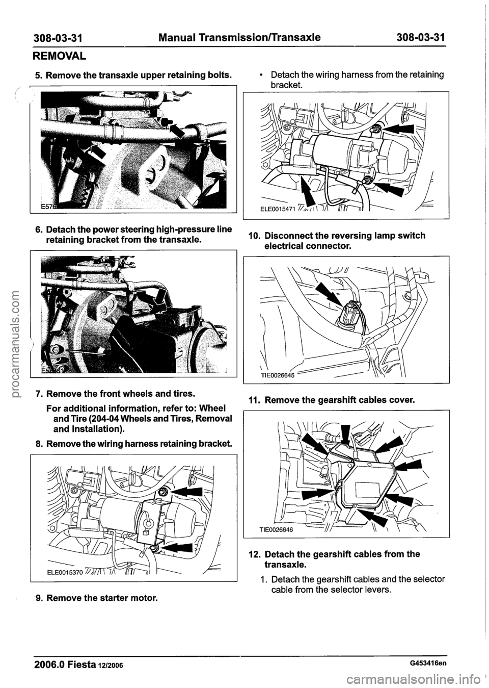
REMOVAL
5. Remove the transaxle upper retaining bolts. Detach the wiring harness from the retaining
bracket.
6. Detach the power steering high-pressure line
retaining bracket from the transaxle. 10.
Disconnect the reversing lamp switch
electrical connector.
7. Remove the front wheels and tires.
11. Remove the gearshift cables cover.
For additional information, refer to: Wheel
and Tire (204-04 Wheels and Tires, Removal
I
and Installation).
8. Remove the wiring harness retaining bracket.
9. Remove the starter motor. 12.
Detach the gearshift cables from the
transaxle.
1. Detach the gearshift cables and the selector
cable from the selector levers.
- -
2006.0 Fiesta 1212006 G453416en
procarmanuals.com
Page 1163 of 1226

308-03-73 Manual Transmission/Transaxle 308-03-73
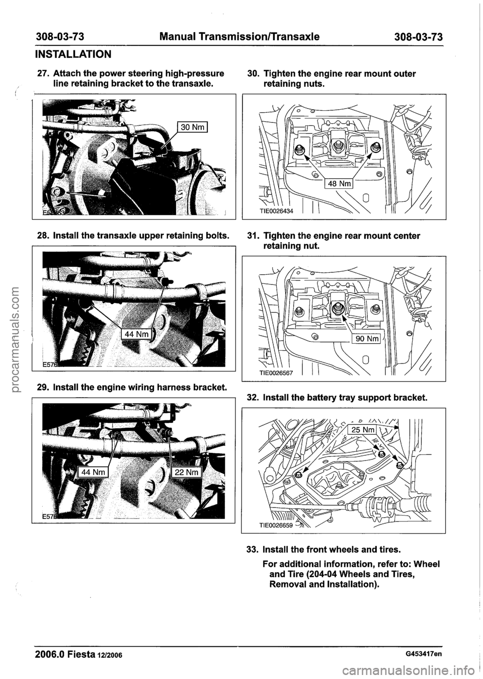
INSTALLATION
27. Attach the power steering high-pressure 30. Tighten the engine rear mount outer
/ line retaining bracket to the transaxle. retaining nuts. I
28. Install the transaxle upper retaining bolts. 31. Tighten the engine rear mount center
retaining nut.
29. Install the engine wiring harness bracket.
32. Install the battery tray support bracket.
33. Install the front wheels and tires.
For additional information, refer to: Wheel
and Tire
(204-04 Wheels and Tires,
Removal and Installation).
- -- -- --
2006.0 Fiesta 1212006 G453417en
procarmanuals.com