2007 FORD FIESTA relay
[x] Cancel search: relayPage 900 of 1226

Engine Emission Control - 2.OL Duratec-HE
303-08B-6
(MI41 303-08B-6
DIAGNOSIS AND TESTING
Engine Emission Control
lnspection and Verification
General Equipment Visual Inspection Chart L..
I. Verify the customer concern.
2. Visually inspect for obvious signs of mechanical
or electrical damage.
Worldwide Diagnostic System
(WDS)
- Hose(s)/hose joints
- Gasket(s)
- Positive crankcase
ventilation (PCV)
valve
- PCV separator
Mechanical
- Exhaust gas recircu-
lation (EGR) valve
Electrical
- Electrical
con
nector(s)
- Wiring harness
- Fuse(s)
- Relay
- EGRvalve
- Powertain control
module (PCM)
3. If an obvious cause for an observed or reported
concern is found, correct the cause (if possible)
before proceeding to the next step.
4. If the concern is not visually evident, verify the
symptom and refer to the Symptom Chart.
Symptom Chart
Symptom Chart
Symptom Possible Sources Action
I
Poor engine performance EGR valve.
Using WDS, CHECK the EGR
Valve Duty Cycle input signal
I to the EGR vacuum regulator
valve. If the result is 0%,
REMOVE the EGR valve.
REFER to Exhaust Gas Recir-
culation (EGR) Valve
- in this
section.
INSPECT the EGR valve and
valve seat for damage. Make
sure that the EGR valve is in
the closed position. If the EGR
valve is not closed. INSTALL
a
new EGR valve. TEST the
system for normal operation. If
the result is not 0% continue
the engine diagnostic using
WDS.
2006.0 Fiesta 1212006 G334290en
Excessive crankcase pressure Blocked or damaged PCV
hose(s).
Blocked crankcase vent oil
separator. CHECK
the PCV system
components for blockages, CLEAN or INSTALL new
components as necessary.
procarmanuals.com
Page 930 of 1226

303-1 4-6 Electronic Engine Controls 303-1 4-6
DESCRIPTION
AND OPERATION
Item Descri~tion
1 5 1 Crankshaft Position (CKP) sensor 1
Throttle Control Unit (TCU)
1 6 ( Camshaft Position (CMP) sensor I Components
1 7 1 Heated Oxygen Sensor (H02S) I
1 8 1 Power Steering Pressure (PSP) sensor I
1 10 1 Brake Pedal Position (BPP) switch I
9 Vehicle Speed Sensor (VSS)
(only on
vehicles without Anti-lock Braking System
(ABS))
1 12 1 Clutch Pedal Position (CPP) switch I
11
1 13 1 Generator I
Accelerator Pedal Position (APP) sensor
1 14 1 Current supply relay I
1 15 1 Ignition key I -
16
17
1 20 1 Inertia fuel shut-off switch I
Battery
Powertrain Control Module (PCM)
-
18
19
1 21 1 Fuel Pump Driver Module (FPDM) I
Data Link Connector (DLC)
Fuel Pump (FP) relay
1 22 1 Fuel injectors I
23 Evaporative emissions (EVAP) solenoid
1 lvalve
1 24 1 Idle Air Control (IAC) valve 1
1 25 1 Throttle Control Unit (TCU) I
26 Air Conditioning (AIC) compressor clutch
1 I 1 blower switch
1 27 1 Injector Driver
Module (IDM) I
1 28 1 Start inhibit relay I
1 29 1 Instrument cluster I
Item Descri~tion
I I ITP sensor I
1 2 1 Electric motor I
The electronically controlled throttle control unit
(TCU) consists of the following components:
Housing
Throttle flap
Throttle flap spindle
Gear set
Electric motor with pinion
TP sensor
Stop screw
Throttle flap return spring
2006.0 Fiesta 1212006 G204204en
procarmanuals.com
Page 943 of 1226

Electronic Engine Controls
DIAGNOSIS AND TESTING
I PO304 I Cylinder No. 4 misfire detected I
/ I
KS implausible signal I
MIL Code
PO303
PO31 5
PO324
1 PO335 1 Crankshaft position (CKP) sensor implausible signal I
Description
Cylinder No. 3 misfire detected
Flywheel segment adaptation at the Limit
Knock sensor (KS) communication error or implausible signal
1 PO336 1 CKP sensor missing teeth I
1 PO336 1 CKP sensor loss of synchronization I
1 PO336 1 CKP sensor no signal I
I PO340 I Camshaft position (CMP) sensor no signal I
I PO341 I CMP sensor implausible signal I
I PO351 I Ignition coil A primary malfunction I
1 PO352 1 Ignition coil B primary malfunction I
I PO420 I Catalyst system efficiency below threshold I
1 PO444 1 Evaporative mission canister purge valve open circuit I
1 PO458 1 Evaporative mission canister purge valve low voltage I
I '1 PO459 1 Evaporative mission canister purge valve high voltage I
I PO460 I Fuel tank level malfunction from instrument cluster I
-3 I VSS signal too high I
PO500
PO500
Vehicle speed sensor (VSS) signal malfunction
Vehicle speed via CAN (VS CAN) implausible signal
PO51 1
PO560
I PO603 I Powertrain control module (PCM) error NVMY or EEPROM error 1
Idle air control (IAC) valve circuit malfunction
Battery system voltage malfunction high voltage
PO562
PO571
I PO604 I PCM error RAM error I
Battery system voltage malfunction open circuit
Brake switch plausibility error
PO605 I PCM error checksum error I
I PO610 I VID block checksum not correct or not programmed I
I PO617 I Starter relay malfunction I
I PO620 I Generator circuit malfunction I
1 PO628 1 Fuel pump primary circuit low voltage I
I
7 1 Fuel pump primary circuit high voltage I
2006.0 Fiesta 1212006 G384566en
PO625
PO626
Generator low voltage
Generator high voltage
procarmanuals.com
Page 944 of 1226

303-1 4-20 Electronic Engine Controls 303-1 4-20
DIAGNOSIS AND TESTING
1 PO643 1 Transmission sensor power supply 1 high voltage I
MIL Code
PO641
PO642
1 PO646 1 Air conditioning (NC) clutch relay circuit low voltage I
1 PO647 1 NC clutch relay circuit high voltage I
Description
Transmission sensor power supply 1 noisy signal
Transmission sensor power supply
I low voltage
I PO651 I Transmission sensor power supply 2 noisy signal I
i
PO652
PO653
Transmission sensor power supply 2 low voltage
Transmission sensor power supply
2 high voltage
PO654
PO686
1 PO692 1 Cooling fan 1 control circuit high voltage I
Engine run output circuit malfunction
Main relay malfunction low voltage
PO687
PO691
1 PO693 1 Cooling fan 2 control circuit low voltage I
Main relay malfunction high voltage
Cooling fan
1 control circuit low voltage
1 PO694 1 Cooling fan 2 control circuit high voltage I
I PI500 I Vehicle speed sensor (VSS) output circuit malfunction I
PO704
PI 000
Generator command malfunction I
Clutch switch implausible signal
EOBD system readiness test not complete
I P2107 I Safety failure level 3 I
PI 794
P2100
I P2108 I Safety failure level 2 error I
Battery voltage malfunction too high or too low
Engine throttle body H-bridge malfunction
APP sensor circuit 1 high input I
P2119
P2122
1 P2127 1 APP sensor circuit 2 low input I
Engine throttle body throttle flap malfunction
Accelerator pedal position (APP) sensor circuit
1 low input
1 P2128 1 APP sensor circuit 2 high input I
1 P2176 1 Engine throttle body adaptive algorithm failed 1
P2128
P2135
APP sensor circuits I and 2 plausibility error
TP sensor circuits 1 and 2 plausibility error
I UOOOl I Control Area Network (CAN) bus-off or mute I
P2280
P2282
I UOlOl I CAN missing frame from TCU I
Air cleaner obstruction or leakage
Air leakage between throttle and inlet valves
2006.0 Fiesta 1212006 G384566en
procarmanuals.com
Page 989 of 1226

Automatic Transmission/Transaxle -
Vehicles With: 4-Speed Automatic
Transmission (AW81-40)
DESCRIPTION AND OPERATION
Item Description
1 5 1 Generic Electronic Module (GEM) I
I
1 6 1 Turbine Shaft Speed (TSS) sensor I
1 7 1 Output Shaft Speed (OSS) sensor I
1
2
3
4
l tem Description
Transmission control unit
Data Link Connector (DLC)
Powertrain Control Module (PCM)
Instrument cluster
1 8 I Transmission Range (TR) sensor I
1 9 1 Starter inhibit relay I
1 10 1 Backup lamp relay I
11 Transmission Fluid Temperature (TFT)
I I sensor
1 12 loverdrive switch I
1 13 1 Driver's side door ajar switch I
1 14 1 Solenoid valves in the main control body 1
Transmission control unit
Item Description
Electrical connector, vehicle wiring
harness
connector, transmission wiring
harness
--
The transmission control unit is located in the
'engine compartment on the left-hand side member.
The transmission control unit evaluates incoming
signals and controls the actuators accordingly.
2006.0 Fiesta 1212006 G380530en
procarmanuals.com
Page 998 of 1226

Automatic Transmission/Transaxle -
Vehicles With: 4Speed Automatic
307-01 -38 Transmission (AW81-40) 307-01 -38
DESCRIPTION AND OPERATION
Consequences of signal failure:
NoTCC,
no torque reduction, no shift timing adaptation,
no 4th
gear.
TR sensor
The TR sensor serves to signal the currently
selected transmission range to the transmission
control unit.
It is a switch which transmits the selected
transmission range directly to the transmission
control unit.
In addition, the starter inhibit relay is actuated by
the PCM via the TR sensor when the selector lever
is in the positions "P" or
N.
In selector lever position "R the backup lamp relay
is also actuated via the TR sensor.
The transmission control unit uses this signal for:
Controlling the main line pressure,
Gearshift control,
Engagement of the TCC,
Shift timing adaptation during upshifts,
Shift timing adaptation during shifts from 3rd to
4th gear,
Shift timing adaptation during shifts from 4th to
3rd gear,
Reverse gear safety strategy,
Avoidance of gearshift judder during
engagement of a transmission range,
Torque reduction when pulling away.
Consequences of signal failure:
NoTCC,
no shift timing adaptation.
2006.0 Fiesta 1212006 G380530en
procarmanuals.com
Page 1002 of 1226

Automatic Transmission/Transaxle -
Vehicles With: 4-Speed Automatic
Transmission
(AW81-40)
DESCRIPTION AND OPERATION
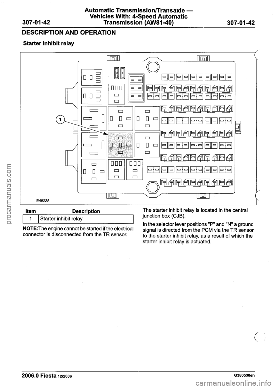
Starter inhibit relay
2006.0 Fiesta
12/2006 G380530en
Item Description The starter inhibit relay is located in the central
1 Starter inhibit relay junction
box (CJB).
In the selector lever positions "P" and "Nu a ground N0TE:The engine cannot be started if the electrical signal is directed from the PCM via the TR sensor connector is disconnected from the TR sensor.
to the starter inhibit relay, as a result of which the
starter inhibit relay is actuated.
procarmanuals.com
Page 1003 of 1226

Automatic Transmission/Transaxle -
Vehicles With: 4-Speed Automatic
307-01 -43 Transmission (AW81-40) 307-01 -43
DESCRIPTION AND OPERATION
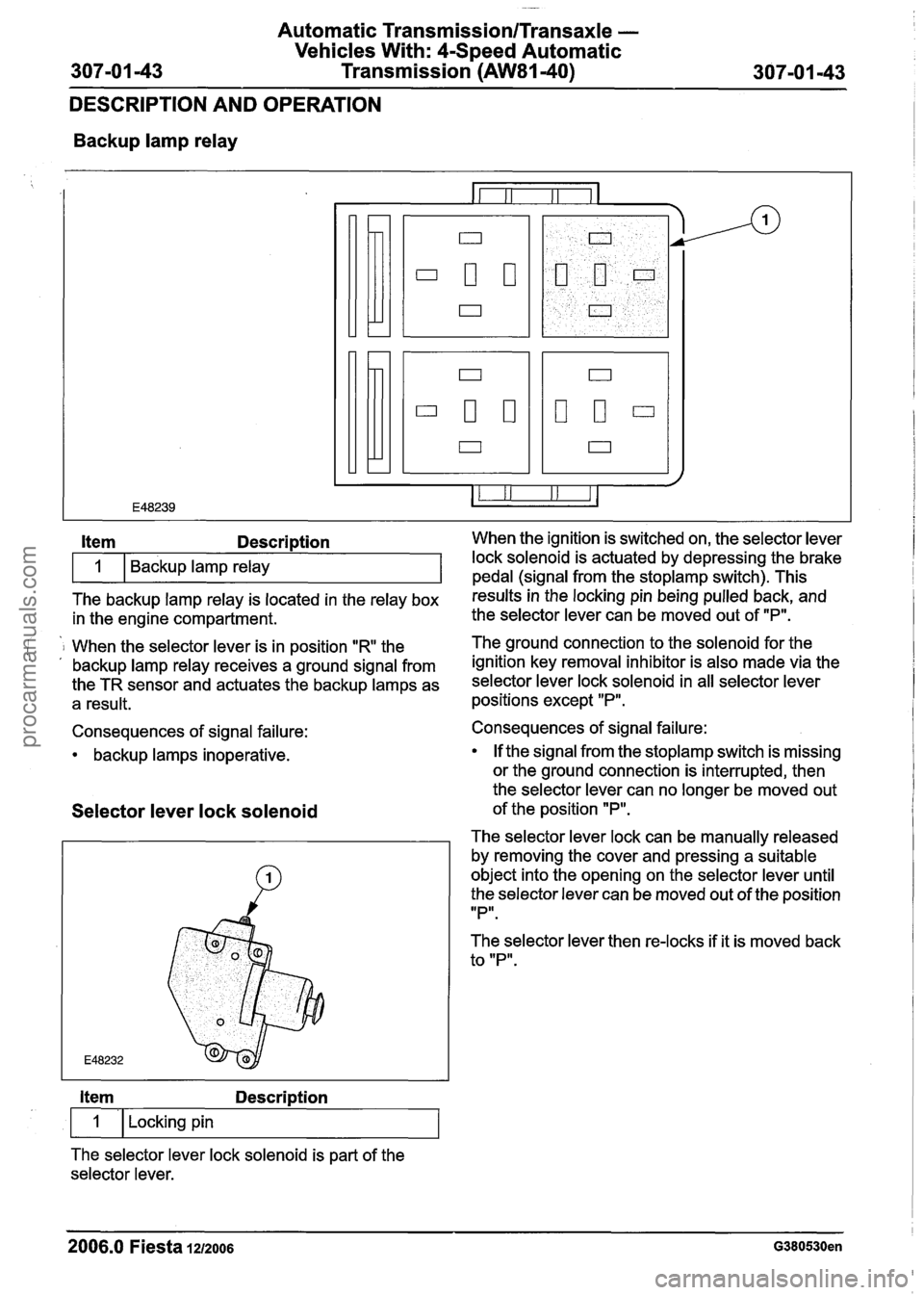
Backup lamp relay
The backup lamp relay is located in the relay box results inthe locking pin being pulled back, and
in the engine compartment. the
selector lever can be moved out of "P".
Item Description When the ignition is switched on, the selector lever
i 1 When the selector lever is in position "R the The ground connection to the solenoid for
the . , backup lamp relay receives a ground signal from ignition key removal inhibitor is also made via the
the TR sensor and actuates the backup lamps as selector lever lock solenoid in all selector lever
a result. positions except "P".
1
Consequences of signal failure:
backup lamps inoperative. Backup lamp relay
Selector
lever lock solenoid
lock solenoid is actuated by depressing the brake
pedal (sianal from the stoplamp switch). This
Item Description
1 I Locking pin
The selector lever lock solenoid is part of the
selector lever. Consequences of signal failure:
If the signal from the
stoplamp switch is missing
or the ground connection is interrupted, then
the selector lever can no longer be moved out
of the position
"P".
The selector lever lock can be manually released
by removing the cover and pressing a suitable
object into the opening on the selector lever until
the selector lever can be moved out of the position
IIPlr.
The selector lever then re-locks if it is moved back
to "P".
2006.0 Fiesta 1212006 G380530en
procarmanuals.com