Page 943 of 1226

Electronic Engine Controls
DIAGNOSIS AND TESTING
I PO304 I Cylinder No. 4 misfire detected I
/ I
KS implausible signal I
MIL Code
PO303
PO31 5
PO324
1 PO335 1 Crankshaft position (CKP) sensor implausible signal I
Description
Cylinder No. 3 misfire detected
Flywheel segment adaptation at the Limit
Knock sensor (KS) communication error or implausible signal
1 PO336 1 CKP sensor missing teeth I
1 PO336 1 CKP sensor loss of synchronization I
1 PO336 1 CKP sensor no signal I
I PO340 I Camshaft position (CMP) sensor no signal I
I PO341 I CMP sensor implausible signal I
I PO351 I Ignition coil A primary malfunction I
1 PO352 1 Ignition coil B primary malfunction I
I PO420 I Catalyst system efficiency below threshold I
1 PO444 1 Evaporative mission canister purge valve open circuit I
1 PO458 1 Evaporative mission canister purge valve low voltage I
I '1 PO459 1 Evaporative mission canister purge valve high voltage I
I PO460 I Fuel tank level malfunction from instrument cluster I
-3 I VSS signal too high I
PO500
PO500
Vehicle speed sensor (VSS) signal malfunction
Vehicle speed via CAN (VS CAN) implausible signal
PO51 1
PO560
I PO603 I Powertrain control module (PCM) error NVMY or EEPROM error 1
Idle air control (IAC) valve circuit malfunction
Battery system voltage malfunction high voltage
PO562
PO571
I PO604 I PCM error RAM error I
Battery system voltage malfunction open circuit
Brake switch plausibility error
PO605 I PCM error checksum error I
I PO610 I VID block checksum not correct or not programmed I
I PO617 I Starter relay malfunction I
I PO620 I Generator circuit malfunction I
1 PO628 1 Fuel pump primary circuit low voltage I
I
7 1 Fuel pump primary circuit high voltage I
2006.0 Fiesta 1212006 G384566en
PO625
PO626
Generator low voltage
Generator high voltage
procarmanuals.com
Page 1188 of 1226
31 0-00-2 Fuel System - General Information 31 0-00-2
DIAGNOSIS AND TESTING
Fuel System - 1.3L Duratec-8V (Rocam)/l.25L Duratec-1 6V
(Sigma)/2.0L Duratec-HE (M14)/1.4L Duratec-I 6V
(Sigma)/l.GL Duratec-1 6V (Sigma)
lnspection and Verification
1. Verify the customer concern.
2. Visually inspect for obvious signs of mechanical
or electrical damage.
- Fuel level
- Fuel leak(s)
- Fuel line(s)
- Fuel filter (if
equipped)
- Fuel tank
- Fuel tank filler pipe
- Fuel filler cap
Visual lnspection Chart
- Electrical
connector(s)
- Wiring harness
- Inertia fuel shutoff
(IFS) switch
- Fuel pump module
I Mechanical
3. If an obvious cause for an observed or reported
concern is found, correct the cause (if possible)
before proceeding to the next step
4. If the cause is not visually evident, verify the
symptom and refer to WDS.
Electrical
-
2006.0 Fiesta 1212006 G348253en
procarmanuals.com
Page 1189 of 1226
31 0-00-3 Fuel System - General Information 31 0-00-3
GENERAL PROCEDURES
/'
Fuel System Pressure Release(23 420 0)
i
Release
I. WARNINGS:
ADO not smoke or carry lighted tobacco or
open flame of any type when working on or
near any fuel related components. Highly
flammable vapors are always present and
may ignite. Failure to follow these
instructions may result in personal injury.
A~he fuel system remains pressurized for
a long time after the ignition is switched off.
The fuel pressure must be released before
attempting any repairs. Failure to follow this
instruction may result in personal injury.
Remove the fuel pump fuse.
2. Start the engine and allow to idle until the
engine stalls.
3. Crank the engine for approximately five
seconds to make sure the fuel injection
supply manifold pressure has been released.
,1 4. Install the fuel pump fuse.
2006.0 Fiesta 1212006 GI 81 91 en
procarmanuals.com
Page 1199 of 1226

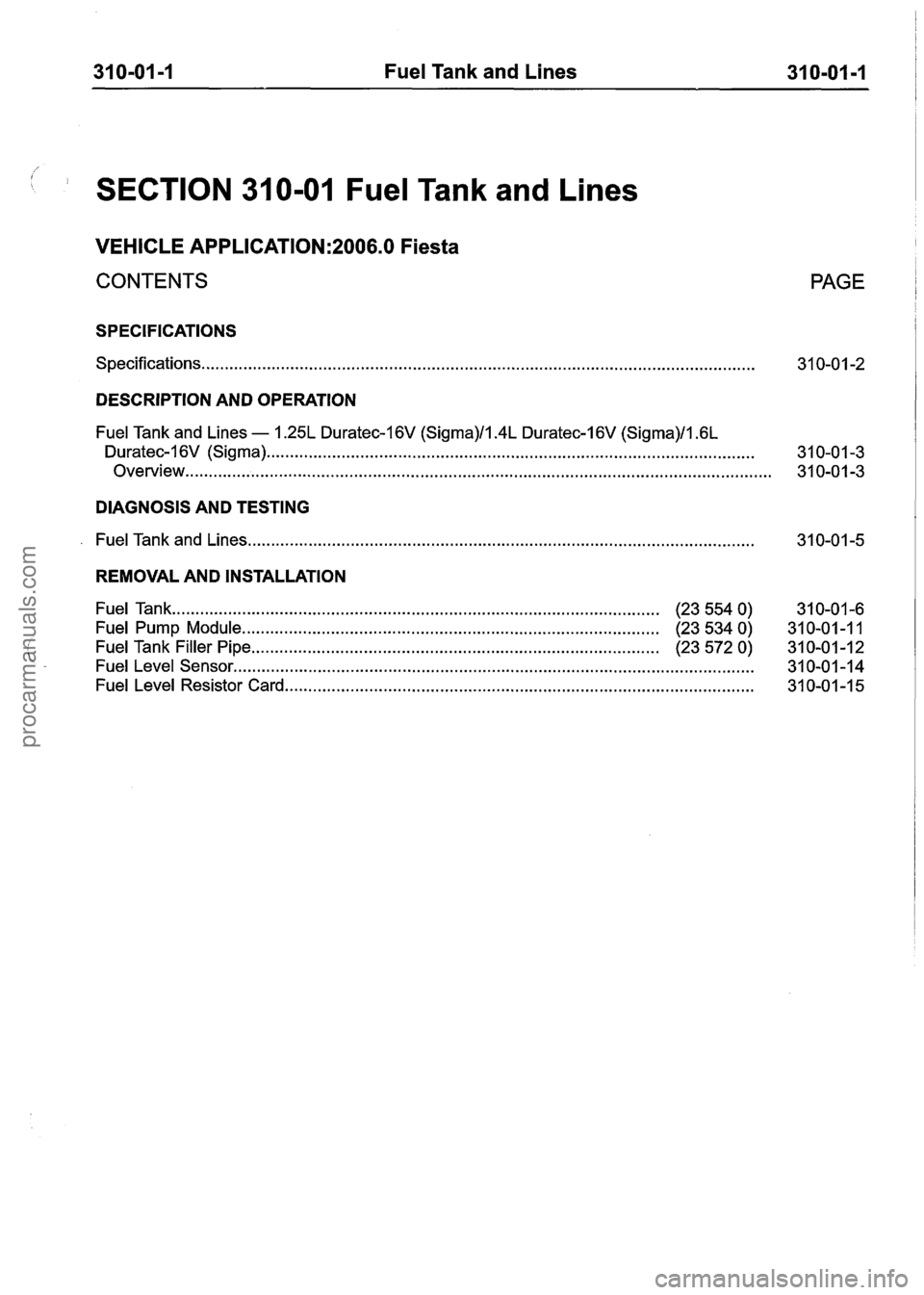
31 0-01 -1 Fuel Tank and Lines 31 0-01 -1
1 SECTION 31 0-01 Fuel Tank and Lines
VEHICLE APPLICATION:2006.0 Fiesta
CONTENTS
SPECIFICATIONS
Specifications.. . . . . . . . . . . . . . . . . . . . . . . . . . . . . . . . . . . . . . . . . . . . . . . . . . . . . . . . . . . . . . . . . . . . . . . . . . . . . . . . . . . . . . . . . . . . . . . . . . . . . . . . . . . . . . . . . . . . .
PAGE
DESCRIPTION AND OPERATION
Fuel Tank and Lines - 1.25L Duratec-I 6V (Sigma)/l.4L Duratec-1 6V (Sigma)/l .6L
Duratec-I 6V (Sigma) ...... . . .. .. .... .. .... . . .... . . . . .... ...... .. .. . . . . ...... . . . . ........ .. .. .. .. . . . . . . . ... .. . . . . . . . . . . .. .... 31 0-01 -3
Overview..
. . . . . . . . . . . . . . . . . . . . . . . . . . . . . . . . . . . . . . . . . . . . . . . . . . . . . . . . . . . . . . . . . . . . . . . . . . . . . . . . . . . . . . . . . . . . . . . . . . . . . . . . . . . . . . . . . . . . . . . . . . . 3 1 0-0 1 -3
DIAGNOSIS AND TESTING
. Fuel Tank and Lines ........................................................................\
....................................
REMOVAL AND INSTALLATION
Fuel Tank ..... . . ...... . . . ... . . ...... .... .. . . . . . . . . . . . . . . . . . . . . . . . . . ...... . . . . . . . . . . . . . . . . . . . (23 554 0)
31 0-01 -6
Fuel Pump Module. ........................................................................\
........ . (23 534 0)
31 0-01 -1 1
Fuel Tank Filler Pipe ........................................................................\
............... (23 572 0) 31 0-01-12
Fuel Level Sensor ..... . . . . . . . . . .. .... .. .. .... .. .. . . .. .. .. . . . . . . . . . . . . .. ...... .. . . .. .... . . .. . . . . .. . . .. .... . ... .. .. .. . . .. . . . . . . .. . 31 0-01 -1 4
Fuel Level Resistor Card ..... . . . . .. .. . . .. . . . . .. . . . . .. ...... . . . . . . . ..... . . . ..... . . . . . . . . . . . . . . . . . . . . . . 31 0-01 -1 5
procarmanuals.com
Page 1200 of 1226
31 0-01 -2 Fuel Tank and Lines 31 0-01 -2
SPECIFICATIONS
Torque Specifications
Description
Nm Ib-ft I b-in I/
Fuel tank support strap retaining bolts I 25 I 18 I -
Fuel tank filler pipe retaining bolts I 9 I - I 80 I
Fuel pump module locking ring - All except vehicles
with diesel engine
Fuel level sensor locking ring
- Vehicles with diesel
engine
Floor panel crossmember
I 4 I - I 35 I
2006.0 Fiesta 1212006 GI 48228en
procarmanuals.com
Page 1201 of 1226

31 0-01 -3 Fuel Tank and Lines 31 0-01 -3
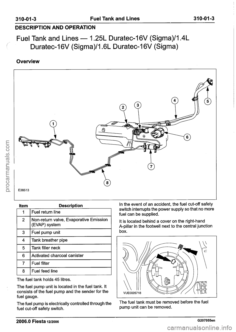
DESCRIPTION AND OPERATION
Fuel Tank and Lines - 1.25L Duratec-1 6V (Sigma)/l.4L
Duratec-1 6V (Sigma)/l .6L Duratec-1 6V (Sigma)
Overview
Item Description In the
event of an accident, the fuel cut-off safety
11 Tank breather pipe I
1
2
3
1 5 1Tankfiller neck I
Fuel return line
1 6 I Activated charcoal canister I
switch interrupts the power supply so that no more
fuel can be supplied.
Non-return valve, Evaporative Emission
(EVAP) system
Fuel pump unit
1 7 1 Fuel filter I
It is located behind a cover on the right-hand
A-pillar in the footwell next to the central junction
box.
1 8 1 Fuel feed line I
The fuel tank holds 45 litres.
a The fuel pump unit is located in the fuel tank. It
consists of the fuel pump and the sender for the
fuel gauge.
The fuel pump is electrically controlled through the
The fuel tank must be removed before the fuel
fuel cut-off safety switch. pump
unit can be removed.
2006.0 Fiesta 1212006 G207055en
procarmanuals.com
Page 1202 of 1226
31 0-01 4 Fuel Tank and Lines 31 0-01 -4 --
DESCRIPTION AND OPERATION
Care must be taken on installation, that the arrows
on the fuel tank and the fuel pump unit point at
each other.
If the alignment is wrong, then the fuel level shown
may be incorrect.
2006.0 Fiesta 1212006 G207055en
procarmanuals.com
Page 1206 of 1226
31 0-01 -8 Fuel Tank and Lines 31 0-01 -8 -- -
REMOVAL AND INSTALLATION
All except vehicles with diesel engine All
except vehicles with diesel engine
12. Disconnect the fuel tank vent pipe from the 14.
Disconnect the fuel pump module electrical '
evaporative emission canister. For connector.
additional information, refer to
Section 310-00 [Fuel System
- General
Information].
All vehicles
13' ~CAUTION:W~~~ lowering the fuel tank,
make sure that excessive strain is not
placed on the fuel lines and electrical
connectors.
Partially lower the fuel tank.
Vehicles with diesel engine
15. Disconnect the fuel level sensor electrical
connector.
All vehicles
16. N0TE:Make note of the color of the fuel
lines to make sure they are connected in
exactly the same positions when installing.
Fuel supply line connectors are white or
are identified by a white band. Fuel return
line connectors are red or are identified by
a red band.
2006.0 Fiesta 1212006 GI 89084en
procarmanuals.com