Page 1 of 128
Introduction 3
Instrument Cluster 8
Warning lights and chimes 8
Gauges 12
Lights 15
Headlamps 15
Turn signal control 16
Bulb replacement 16
Driver Controls 17
Windshield wiper/washer control 17
Steering wheel adjustment 17
Speed control 18
Tires, Wheels and Loading 21
Tire information 21
Tire inflation 23
Vehicle loading 38
Trailer towing 43
Driving 46
Starting 46
Brakes 49
Transmission operation 53
Roadside Emergencies 58
Getting roadside assistance 58
Hazard flasher switch 59
Fuel pump shut-off switch 59
Fuses and relays 60
Changing tires 67
Lug nut torque 71
Jump starting 72
Wrecker towing 76
Table of Contents
1
2007 Motorhome(mot)
Supplement
USA(fus)
Page 53 of 128
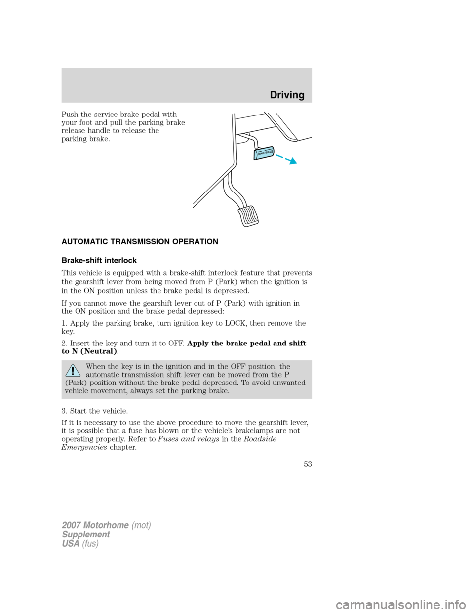
Push the service brake pedal with
your foot and pull the parking brake
release handle to release the
parking brake.
AUTOMATIC TRANSMISSION OPERATION
Brake-shift interlock
This vehicle is equipped with a brake-shift interlock feature that prevents
the gearshift lever from being moved from P (Park) when the ignition is
in the ON position unless the brake pedal is depressed.
If you cannot move the gearshift lever out of P (Park) with ignition in
the ON position and the brake pedal depressed:
1. Apply the parking brake, turn ignition key to LOCK, then remove the
key.
2. Insert the key and turn it to OFF.Apply the brake pedal and shift
to N (Neutral).
When the key is in the ignition and in the OFF position, the
automatic transmission shift lever can be moved from the P
(Park) position without the brake pedal depressed. To avoid unwanted
vehicle movement, always set the parking brake.
3. Start the vehicle.
If it is necessary to use the above procedure to move the gearshift lever,
it is possible that a fuse has blown or the vehicle’s brakelamps are not
operating properly. Refer toFuses and relaysin theRoadside
Emergencieschapter.
2007 Motorhome(mot)
Supplement
USA(fus)
Driving
53
Page 60 of 128
2. Check the fuel system for leaks.
3. If no fuel leak is apparent, reset the fuel pump shut-off switch by
pushing in on the reset button.
4. Turn the ignition to the ON position. Pause for a few seconds and
return the key to the OFF position.
5. Make a further check for leaks in the fuel system.
FUSES AND RELAYS
Standard fuse amperage rating and color
COLOR
Fuse
ratingMini
fusesStandard
fusesMaxi
fusesCartridge
maxi
fusesFuse link
cartridge
2A Grey Grey — — —
3A Violet Violet — — —
4A Pink Pink — — —
5A Tan Tan — — —
7.5A Brown Brown — — —
10A Red Red — — —
15A Blue Blue — — —
20A Yellow Yellow Yellow Blue Blue
25A Natural Natural — — —
30A Green Green Green Pink Pink
40A — — Orange Green Green
50A — — Red Red Red
60A — — Blue Yellow Yellow
70A — — Tan — Brown
80A — — Natural Black Black
Passenger compartment fuse panel
The fuse panel is located below and to the left of the steering wheel by
the brake pedal. Remove the panel cover to access the fuses.
To remove a fuse use the fuse puller tool provided on the fuse panel
cover.
2007 Motorhome(mot)
Supplement
USA(fus)
Roadside Emergencies
60
Page 61 of 128
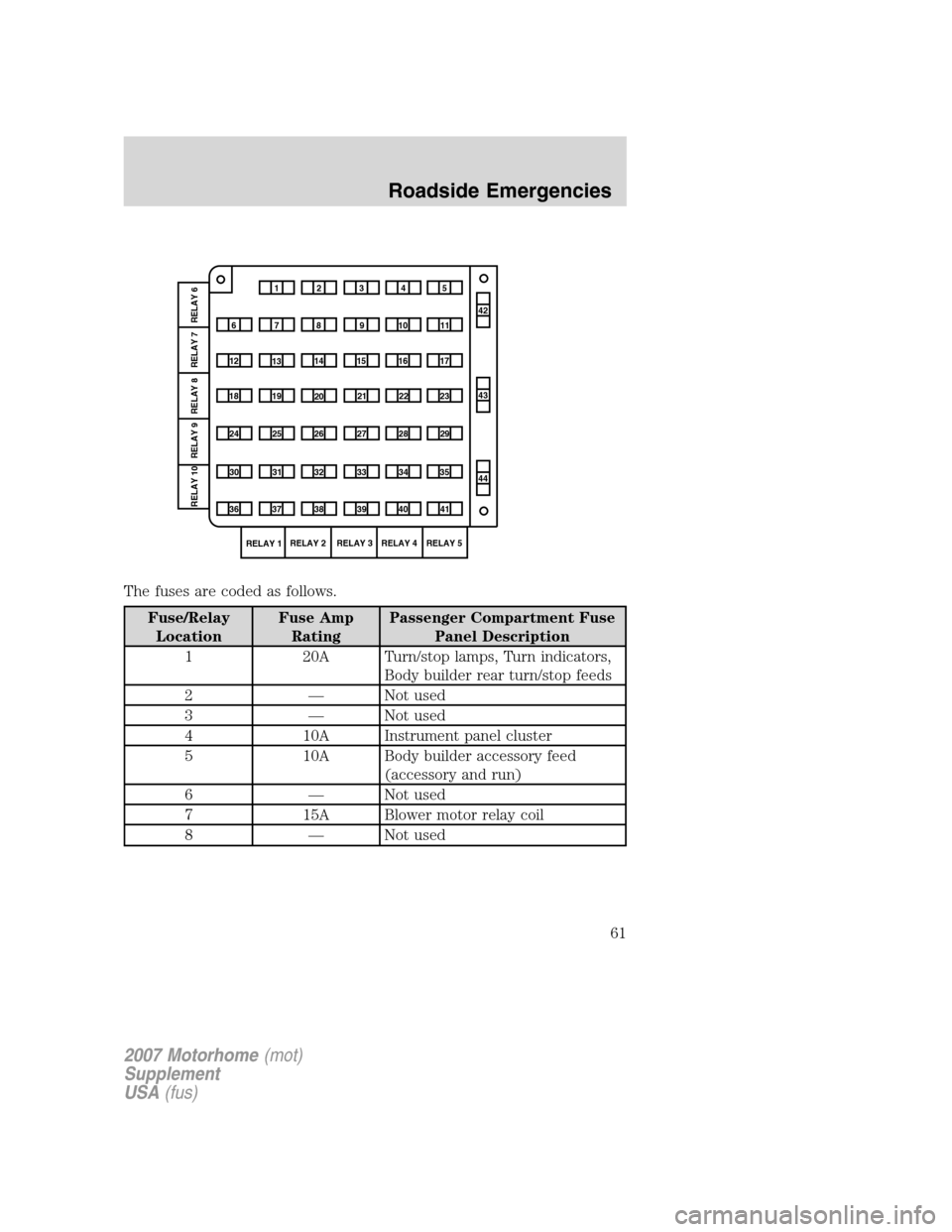
The fuses are coded as follows.
Fuse/Relay
LocationFuse Amp
RatingPassenger Compartment Fuse
Panel Description
1 20A Turn/stop lamps, Turn indicators,
Body builder rear turn/stop feeds
2 — Not used
3 — Not used
4 10A Instrument panel cluster
5 10A Body builder accessory feed
(accessory and run)
6 — Not used
7 15A Blower motor relay coil
8 — Not used
1234
5
7
689101142
43
44 13 12 14
15 16 17
19 18
2021 22 23
25 24
26 27 28 29
31 30 32 33 3435
37
3638 3940
41
RELAY 1RELAY 2 RELAY 3 RELAY 4 RELAY 5
RELAY 7 RELAY 8 RELAY 9 RELAY 10 RELAY 6
2007 Motorhome(mot)
Supplement
USA(fus)
Roadside Emergencies
61
Page 63 of 128
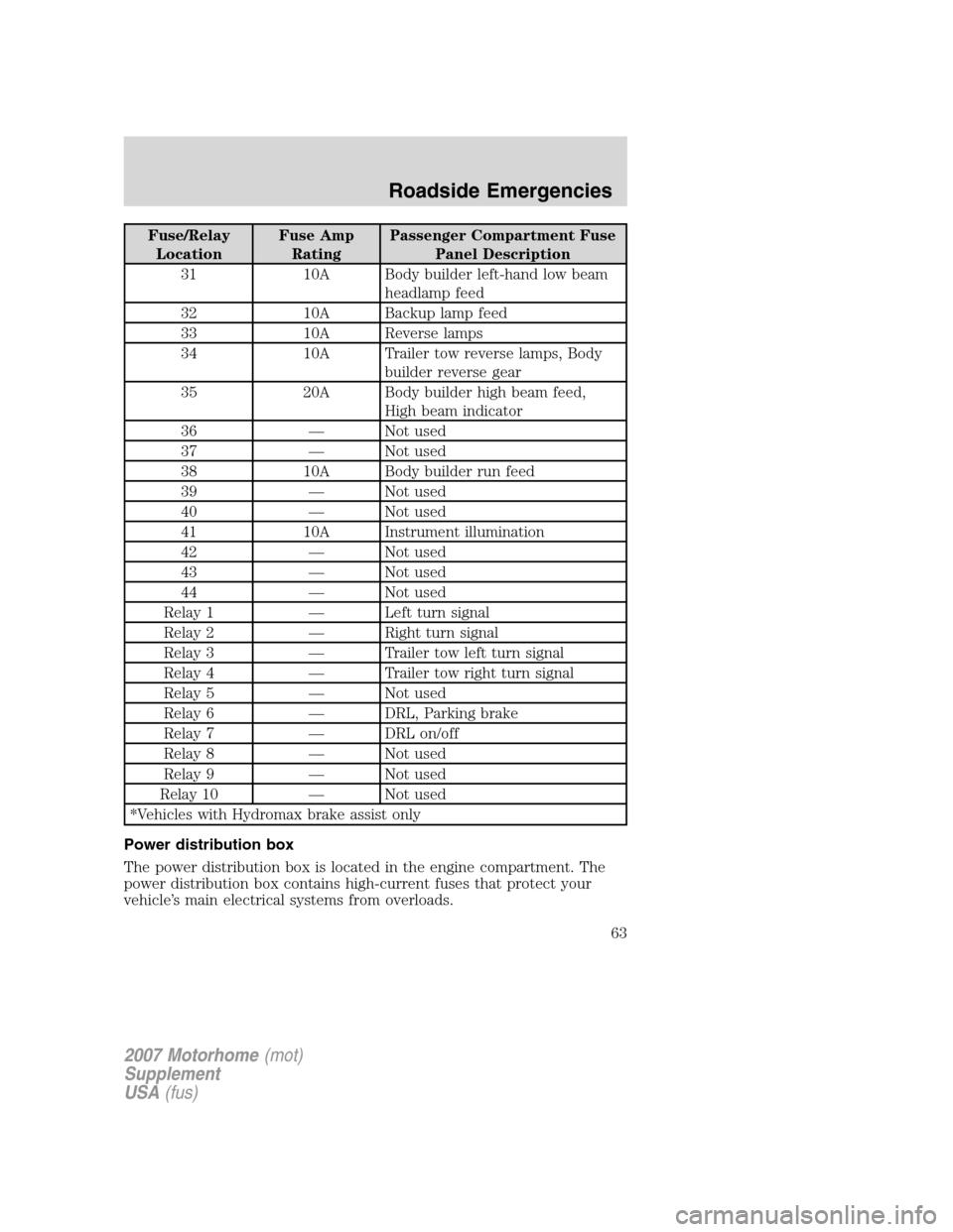
Fuse/Relay
LocationFuse Amp
RatingPassenger Compartment Fuse
Panel Description
31 10A Body builder left-hand low beam
headlamp feed
32 10A Backup lamp feed
33 10A Reverse lamps
34 10A Trailer tow reverse lamps, Body
builder reverse gear
35 20A Body builder high beam feed,
High beam indicator
36 — Not used
37 — Not used
38 10A Body builder run feed
39 — Not used
40 — Not used
41 10A Instrument illumination
42 — Not used
43 — Not used
44 — Not used
Relay 1 — Left turn signal
Relay 2 — Right turn signal
Relay 3 — Trailer tow left turn signal
Relay 4 — Trailer tow right turn signal
Relay 5 — Not used
Relay 6 — DRL, Parking brake
Relay 7 — DRL on/off
Relay 8 — Not used
Relay 9 — Not used
Relay 10 — Not used
*Vehicles with Hydromax brake assist only
Power distribution box
The power distribution box is located in the engine compartment. The
power distribution box contains high-current fuses that protect your
vehicle’s main electrical systems from overloads.
2007 Motorhome(mot)
Supplement
USA(fus)
Roadside Emergencies
63
Page 64 of 128
Always disconnect the battery before servicing high current
fuses.
To reduce risk of electrical shock, always replace the cover to
the Power Distribution Box before reconnecting the battery or
refilling fluid reservoirs.
If the battery has been disconnected and reconnected, refer to the
Batterysection of theMaintenance and Specificationschapter.
2007 Motorhome(mot)
Supplement
USA(fus)
Roadside Emergencies
64
Page 65 of 128
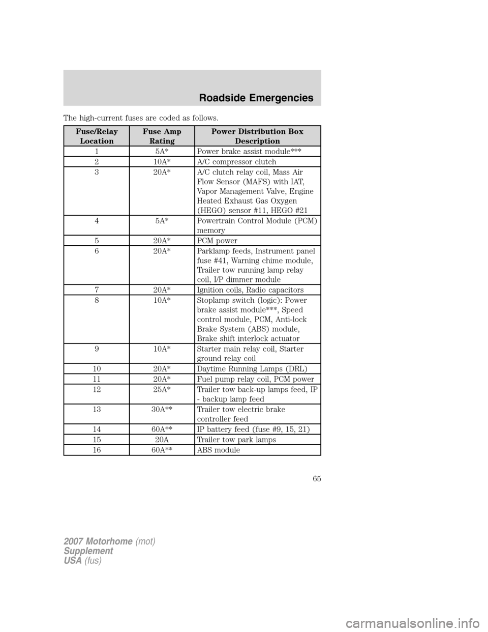
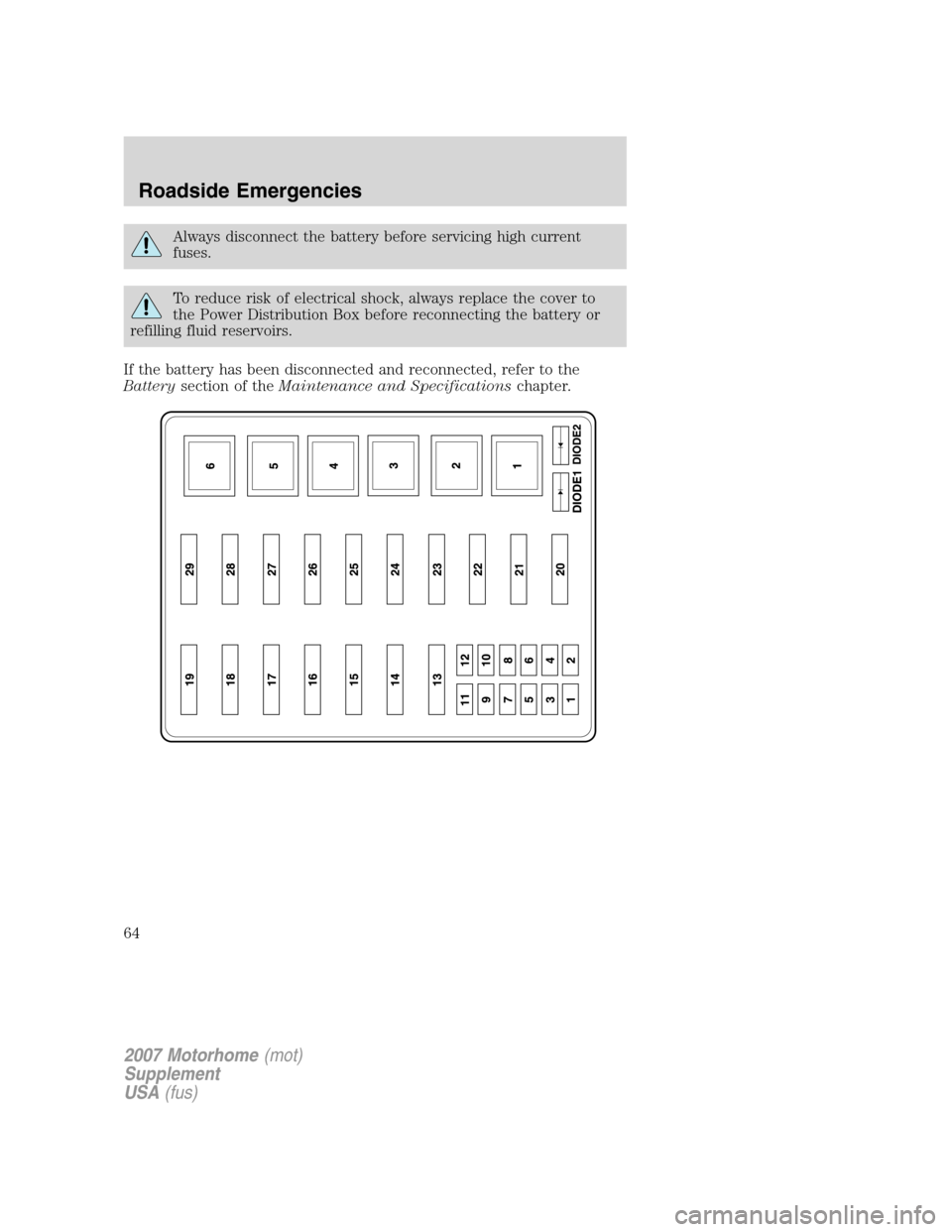
The high-current fuses are coded as follows.
Fuse/Relay
LocationFuse Amp
RatingPower Distribution Box
Description
1 5A* Power brake assist module***
2 10A* A/C compressor clutch
3 20A* A/C clutch relay coil, Mass Air
Flow Sensor (MAFS) with IAT,
Vapor Management Valve, Engine
Heated Exhaust Gas Oxygen
(HEGO) sensor #11, HEGO #21
4 5A* Powertrain Control Module (PCM)
memory
5 20A* PCM power
6 20A* Parklamp feeds, Instrument panel
fuse #41, Warning chime module,
Trailer tow running lamp relay
coil, I/P dimmer module
7 20A* Ignition coils, Radio capacitors
8 10A* Stoplamp switch (logic): Power
brake assist module***, Speed
control module, PCM, Anti-lock
Brake System (ABS) module,
Brake shift interlock actuator
9 10A* Starter main relay coil, Starter
ground relay coil
10 20A* Daytime Running Lamps (DRL)
11 20A* Fuel pump relay coil, PCM power
12 25A* Trailer tow back-up lamps feed, IP
- backup lamp feed
13 30A** Trailer tow electric brake
controller feed
14 60A** IP battery feed (fuse #9, 15, 21)
15 20A Trailer tow park lamps
16 60A** ABS module
2007 Motorhome(mot)
Supplement
USA(fus)
Roadside Emergencies
65
Page 66 of 128
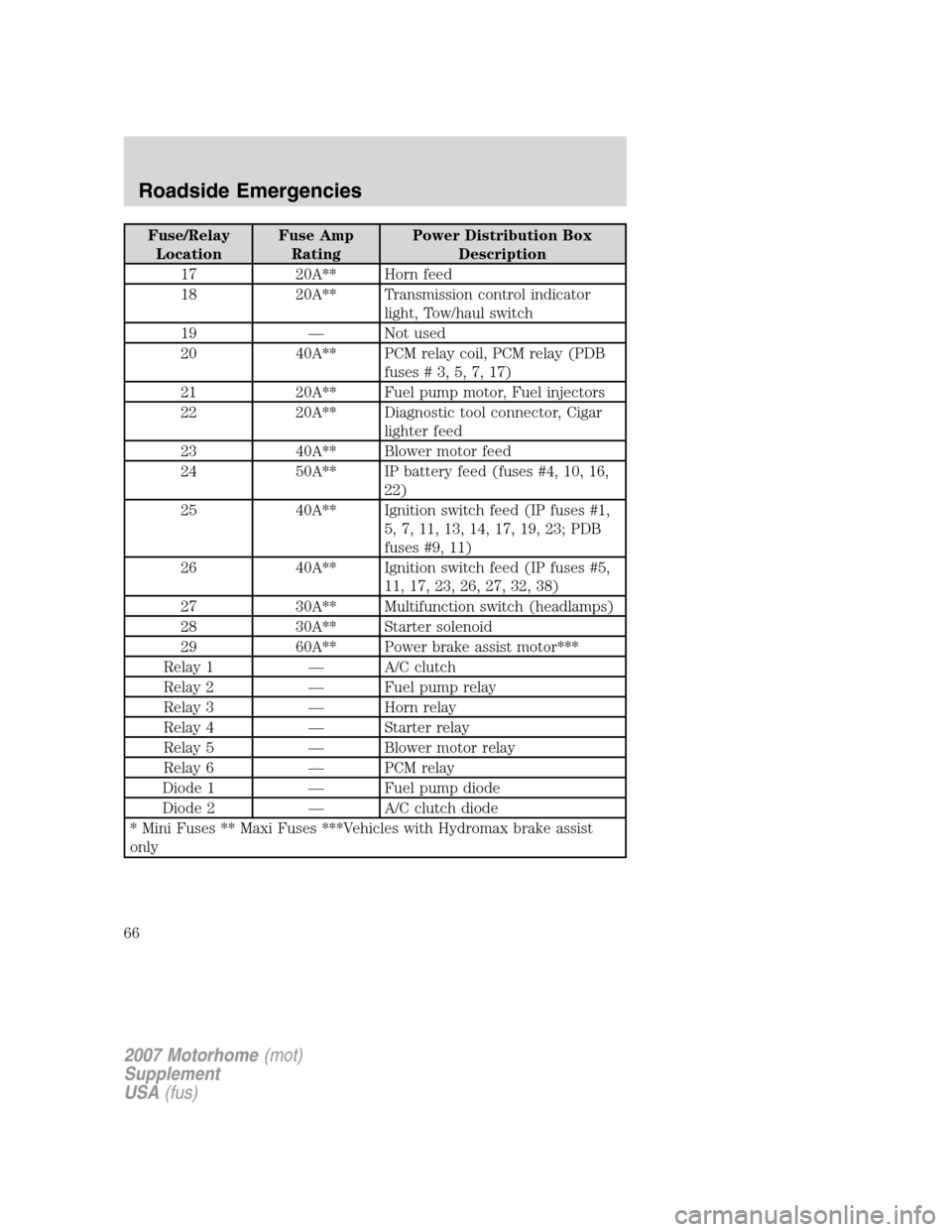
Fuse/Relay
LocationFuse Amp
RatingPower Distribution Box
Description
17 20A** Horn feed
18 20A** Transmission control indicator
light, Tow/haul switch
19 — Not used
20 40A** PCM relay coil, PCM relay (PDB
fuses#3,5,7,17)
21 20A** Fuel pump motor, Fuel injectors
22 20A** Diagnostic tool connector, Cigar
lighter feed
23 40A** Blower motor feed
24 50A** IP battery feed (fuses #4, 10, 16,
22)
25 40A** Ignition switch feed (IP fuses #1,
5, 7, 11, 13, 14, 17, 19, 23; PDB
fuses #9, 11)
26 40A** Ignition switch feed (IP fuses #5,
11, 17, 23, 26, 27, 32, 38)
27 30A** Multifunction switch (headlamps)
28 30A** Starter solenoid
29 60A** Power brake assist motor***
Relay 1 — A/C clutch
Relay 2 — Fuel pump relay
Relay 3 — Horn relay
Relay 4 — Starter relay
Relay 5 — Blower motor relay
Relay 6 — PCM relay
Diode 1 — Fuel pump diode
Diode 2 — A/C clutch diode
* Mini Fuses ** Maxi Fuses ***Vehicles with Hydromax brake assist
only
2007 Motorhome(mot)
Supplement
USA(fus)
Roadside Emergencies
66