Page 2 of 128
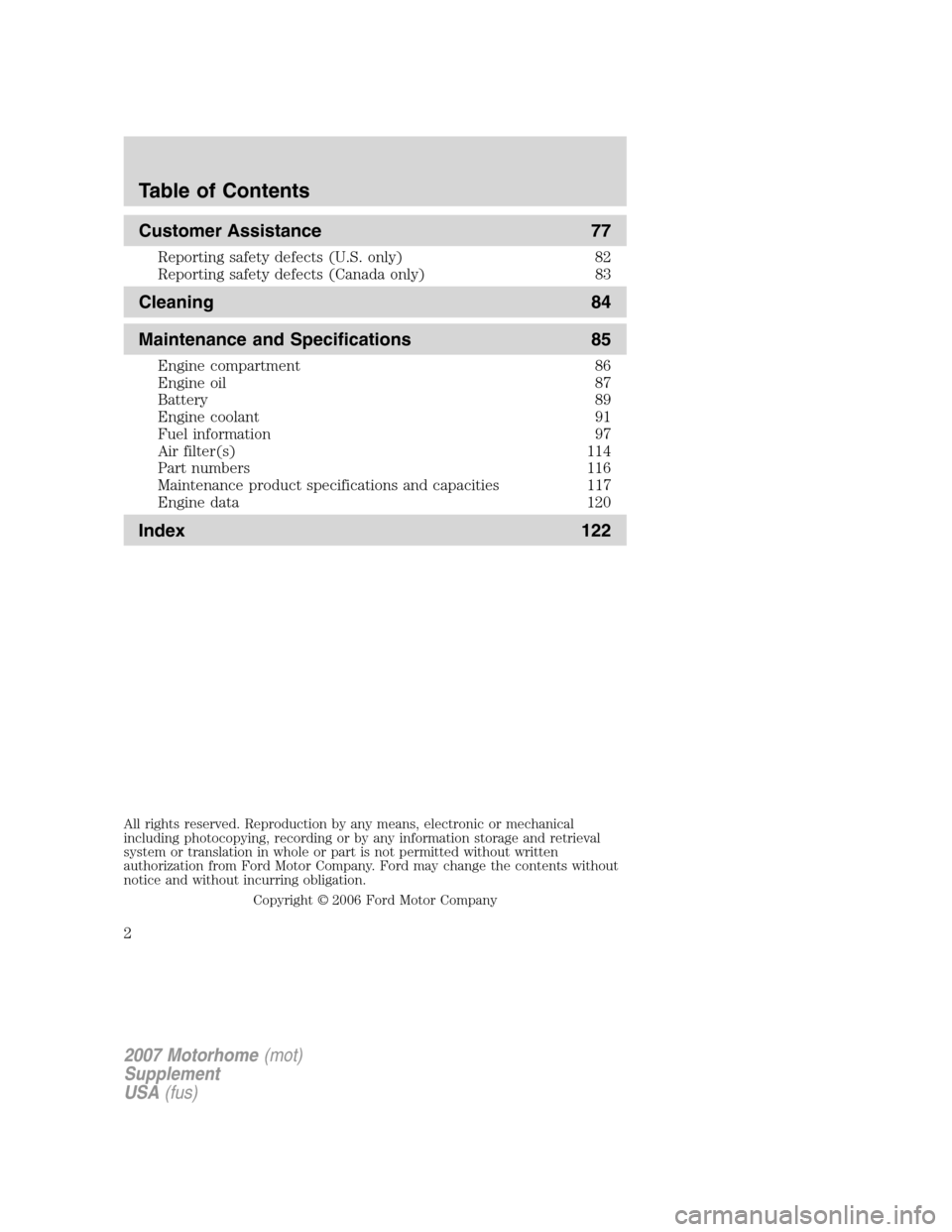
Customer Assistance 77
Reporting safety defects (U.S. only) 82
Reporting safety defects (Canada only) 83
Cleaning 84
Maintenance and Specifications 85
Engine compartment 86
Engine oil 87
Battery 89
Engine coolant 91
Fuel information 97
Air filter(s) 114
Part numbers 116
Maintenance product specifications and capacities 117
Engine data 120
Index 122
All rights reserved. Reproduction by any means, electronic or mechanical
including photocopying, recording or by any information storage and retrieval
system or translation in whole or part is not permitted without written
authorization from Ford Motor Company. Ford may change the contents without
notice and without incurring obligation.
Copyright © 2006 Ford Motor Company
Table of Contents
2
2007 Motorhome(mot)
Supplement
USA(fus)
Page 7 of 128
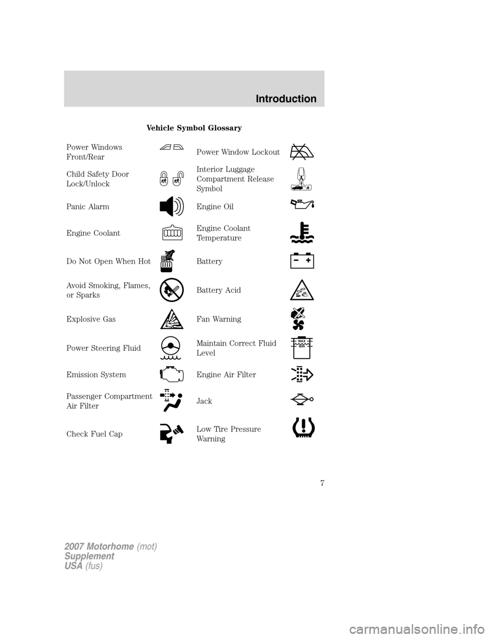
Vehicle Symbol Glossary
Power Windows
Front/Rear
Power Window Lockout
Child Safety Door
Lock/UnlockInterior Luggage
Compartment Release
Symbol
Panic AlarmEngine Oil
Engine CoolantEngine Coolant
Temperature
Do Not Open When HotBattery
Avoid Smoking, Flames,
or SparksBattery Acid
Explosive GasFan Warning
Power Steering FluidMaintain Correct Fluid
LevelMAX
MIN
Emission SystemEngine Air Filter
Passenger Compartment
Air FilterJack
Check Fuel CapLow Tire Pressure
Warning
2007 Motorhome(mot)
Supplement
USA(fus)
Introduction
7
Page 10 of 128

Anti-lock brake system:If the
ABS light stays illuminated or
continues to flash, a malfunction has
been detected, have the system
serviced immediately by your
authorized dealer. Normal braking is still functional unless the brake
warning light also is illuminated.
Safety belt: Reminds you to fasten
your safety belt. A BeltMinder �
chime will also sound to remind you
to fasten your safety belt.
Charging system: Illuminates when
the battery is not charging properly.
Transmission Tow/Haul Feature:
Illuminates when the Tow/Haul
feature has been activated. Refer to
the Driving chapter for
transmission function and operation. If the light flashes steadily, have the
system serviced immediately, damage to the transmission could occur.
Speed control: Illuminates when
the speed control is activated. Turns
off when the speed control system
is deactivated.
Turn signal: Illuminates when the
left or right turn signal or the
hazard lights are turned on. If the
indicators stay on or flash faster, check for a burned out bulb.
High beams: Illuminates when the
high beam headlamps are turned on.
MINI MESSAGE CENTER DISPLAYS
With the ignition in the ON position, the mini message center, located on
your instrument cluster, displays text messages that alert you to possible
problems or malfunctions in your vehicle’s operating systems.
Note: The following warning messages will reappear on the display every
ten minutes.
ABS
2007 Motorhome (mot)
Supplement
USA (fus)
Instrument Cluster
10
Page 54 of 128
Do not drive your vehicle until you verify that the brakelamps
are working.
Always set the parking brake fully and make sure the gearshift is
latched in P (Park). Turn the ignition to the LOCK position and
remove the key whenever you leave your vehicle.
If the parking brake is fully released, but the brake warning lamp
remains illuminated, the brakes may not be working properly.
See your authorized dealer.
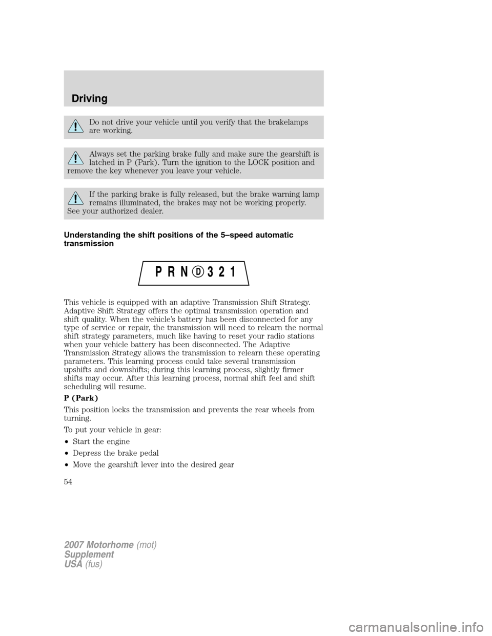
Understanding the shift positions of the 5–speed automatic
transmission
This vehicle is equipped with an adaptive Transmission Shift Strategy.
Adaptive Shift Strategy offers the optimal transmission operation and
shift quality. When the vehicle’s battery has been disconnected for any
type of service or repair, the transmission will need to relearn the normal
shift strategy parameters, much like having to reset your radio stations
when your vehicle battery has been disconnected. The Adaptive
Transmission Strategy allows the transmission to relearn these operating
parameters. This learning process could take several transmission
upshifts and downshifts; during this learning process, slightly firmer
shifts may occur. After this learning process, normal shift feel and shift
scheduling will resume.
P (Park)
This position locks the transmission and prevents the rear wheels from
turning.
To put your vehicle in gear:
•Start the engine
•Depress the brake pedal
•Move the gearshift lever into the desired gear
2007 Motorhome(mot)
Supplement
USA(fus)
Driving
54
Page 58 of 128
ROADSIDE ASSISTANCE
Getting roadside assistance
To fully assist if you should have a vehicle concern, Ford Motor Company
offers a complimentary roadside assistance program. This program is
separate from the New Vehicle Limited Warranty. The service is available:
•24–hours, seven days a week
•for the period of five years or 60,000 miles (100,000 km), whichever
occurs first.
Roadside assistance will cover:
•a flat tire change with a good spare
•battery jump start
•lock-out assistance (key replacement cost is the customer’s
responsibility)
•fuel delivery (fuel cost is the customer’s responsibility)
•towing of your disabled vehicle to the nearest authorized dealer
Canadian customers refer to your Customer Information Guide
for information on:
•coverage period
•exact fuel amounts
•towing of your disabled vehicle
Using roadside assistance
Customers in the U.S. and Canada who require roadside assistance, may
contact 1–800–444–3311.
2007 Motorhome(mot)
Supplement
USA(fus)
Roadside Emergencies
58
Page 62 of 128
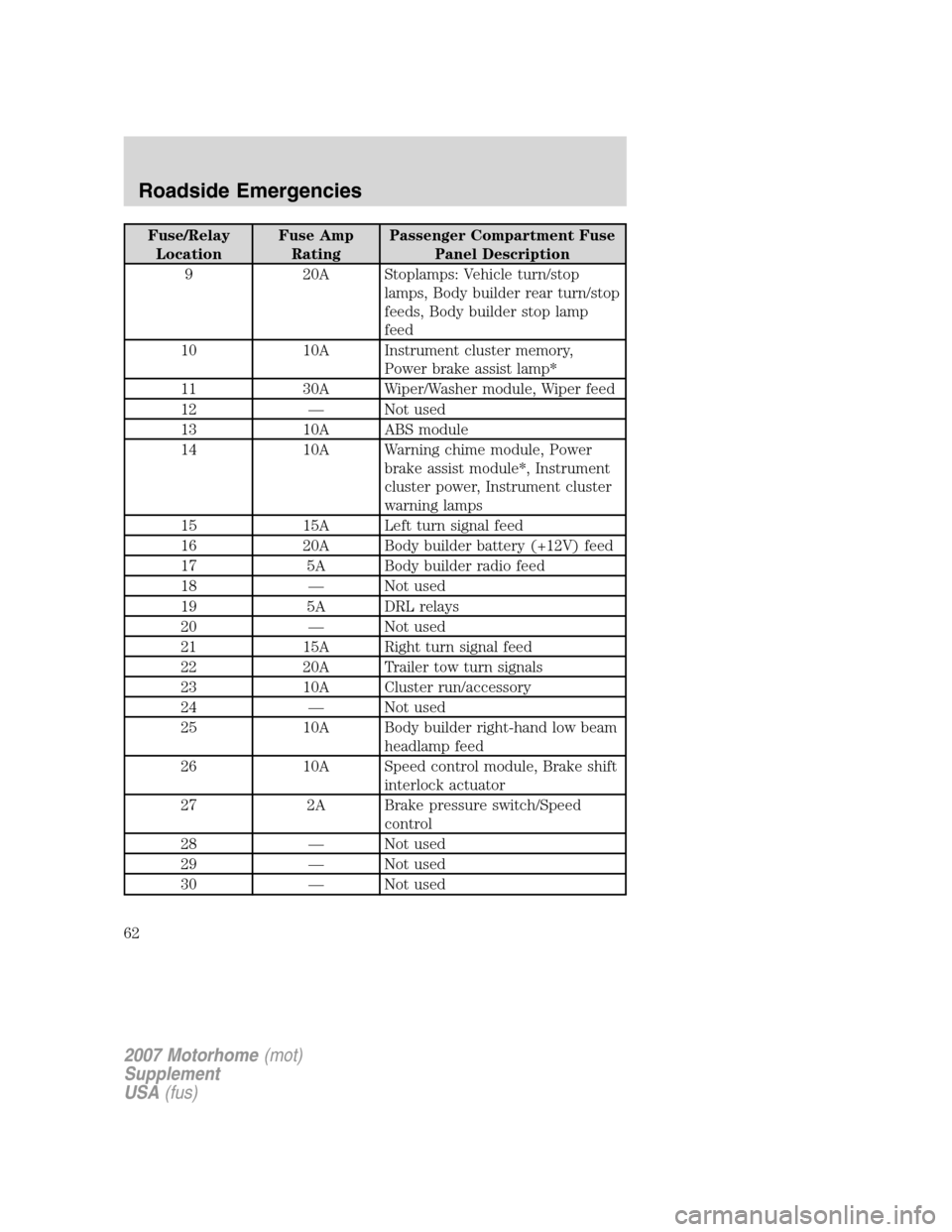
Fuse/Relay
LocationFuse Amp
RatingPassenger Compartment Fuse
Panel Description
9 20A Stoplamps: Vehicle turn/stop
lamps, Body builder rear turn/stop
feeds, Body builder stop lamp
feed
10 10A Instrument cluster memory,
Power brake assist lamp*
11 30A Wiper/Washer module, Wiper feed
12 — Not used
13 10A ABS module
14 10A Warning chime module, Power
brake assist module*, Instrument
cluster power, Instrument cluster
warning lamps
15 15A Left turn signal feed
16 20A Body builder battery (+12V) feed
17 5A Body builder radio feed
18 — Not used
19 5A DRL relays
20 — Not used
21 15A Right turn signal feed
22 20A Trailer tow turn signals
23 10A Cluster run/accessory
24 — Not used
25 10A Body builder right-hand low beam
headlamp feed
26 10A Speed control module, Brake shift
interlock actuator
27 2A Brake pressure switch/Speed
control
28 — Not used
29 — Not used
30 — Not used
2007 Motorhome(mot)
Supplement
USA(fus)
Roadside Emergencies
62
Page 64 of 128
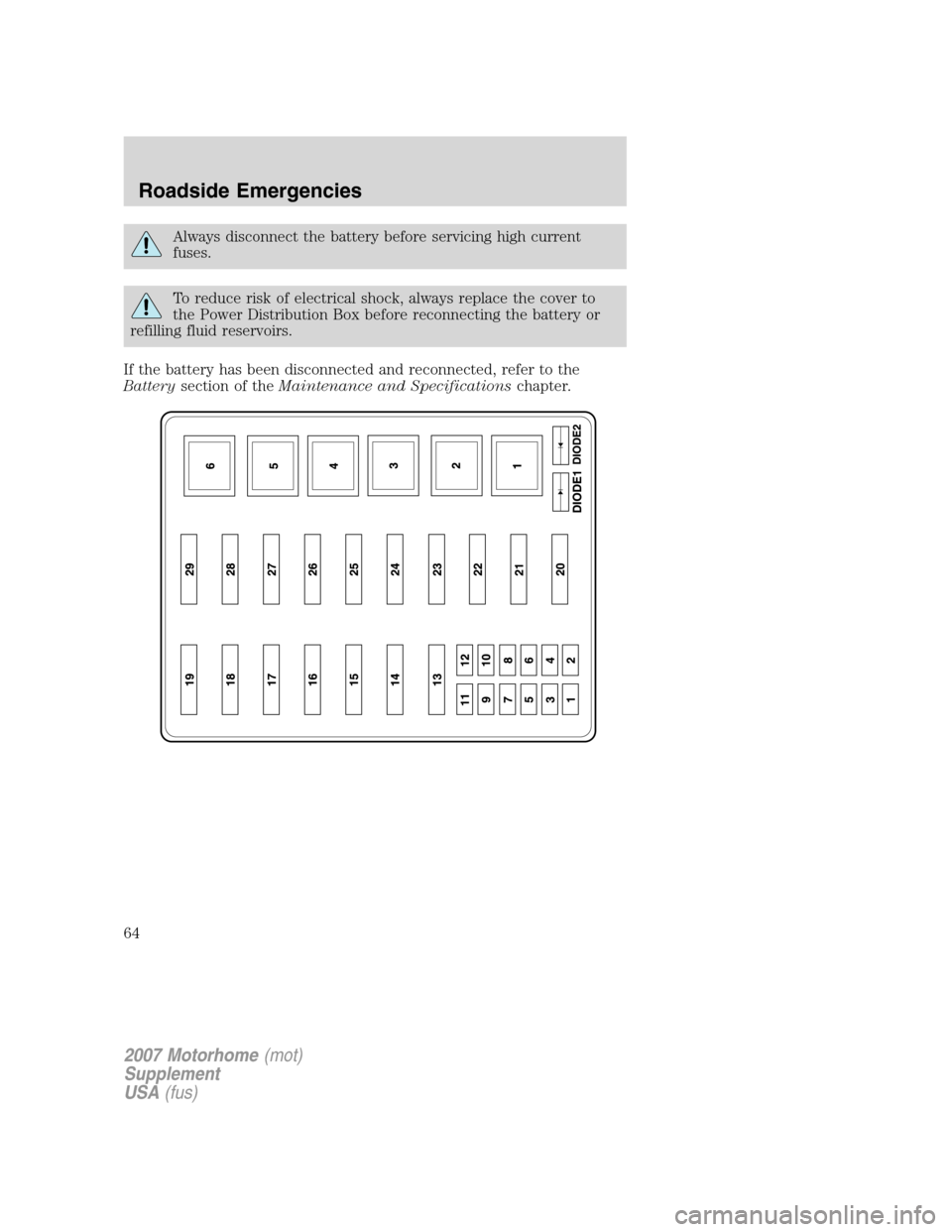
Always disconnect the battery before servicing high current
fuses.
To reduce risk of electrical shock, always replace the cover to
the Power Distribution Box before reconnecting the battery or
refilling fluid reservoirs.
If the battery has been disconnected and reconnected, refer to the
Batterysection of theMaintenance and Specificationschapter.
2007 Motorhome(mot)
Supplement
USA(fus)
Roadside Emergencies
64
Page 65 of 128
The high-current fuses are coded as follows.
Fuse/Relay
LocationFuse Amp
RatingPower Distribution Box
Description
1 5A* Power brake assist module***
2 10A* A/C compressor clutch
3 20A* A/C clutch relay coil, Mass Air
Flow Sensor (MAFS) with IAT,
Vapor Management Valve, Engine
Heated Exhaust Gas Oxygen
(HEGO) sensor #11, HEGO #21
4 5A* Powertrain Control Module (PCM)
memory
5 20A* PCM power
6 20A* Parklamp feeds, Instrument panel
fuse #41, Warning chime module,
Trailer tow running lamp relay
coil, I/P dimmer module
7 20A* Ignition coils, Radio capacitors
8 10A* Stoplamp switch (logic): Power
brake assist module***, Speed
control module, PCM, Anti-lock
Brake System (ABS) module,
Brake shift interlock actuator
9 10A* Starter main relay coil, Starter
ground relay coil
10 20A* Daytime Running Lamps (DRL)
11 20A* Fuel pump relay coil, PCM power
12 25A* Trailer tow back-up lamps feed, IP
- backup lamp feed
13 30A** Trailer tow electric brake
controller feed
14 60A** IP battery feed (fuse #9, 15, 21)
15 20A Trailer tow park lamps
16 60A** ABS module
2007 Motorhome(mot)
Supplement
USA(fus)
Roadside Emergencies
65