Page 112 of 314

111
SAFETY
DEVICES
CORRECT USE
OF THE CAR
WARNING
LIGHTS AND
MESSAGES
IN AN
EMERGENCY
CAR
MAINTENANCE
TECHNICAL
SPECIFICATIONS
INDEX
DASHBOARD
AND CONTROLS
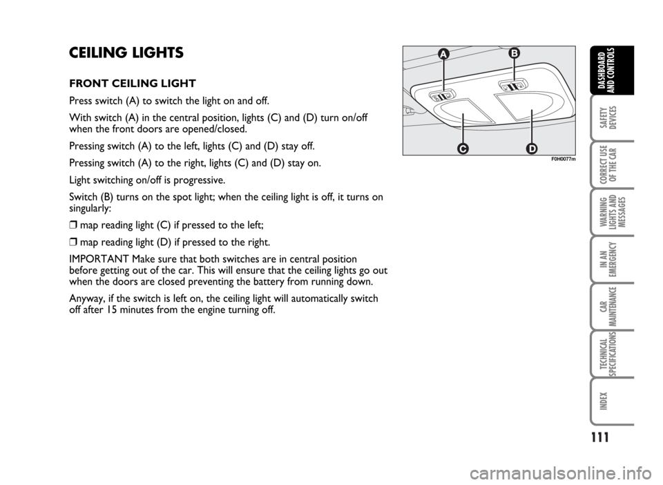
CEILING LIGHTS
FRONT CEILING LIGHT
Press switch (A) to switch the light on and off.
With switch (A) in the central position, lights (C) and (D) turn on/off
when the front doors are opened/closed.
Pressing switch (A) to the left, lights (C) and (D) stay off.
Pressing switch (A) to the right, lights (C) and (D) stay on.
Light switching on/off is progressive.
Switch (B) turns on the spot light; when the ceiling light is off, it turns on
singularly:
❒map reading light (C) if pressed to the left;
❒map reading light (D) if pressed to the right.
IMPORTANT Make sure that both switches are in central position
before getting out of the car. This will ensure that the ceiling lights go out
when the doors are closed preventing the battery from running down.
Anyway, if the switch is left on, the ceiling light will automatically switch
off after 15 minutes from the engine turning off.
F0H0077m
Page 113 of 314
Ceiling light timing
Two timing strategies are available in order to facilitate
getting in and out of the car, especially at night in dark
areas:
T
IMING FOR GETTING INTO THE CAR
The ceiling lights will come on as follows:
❒for about 10 seconds when a door is unlocked;
❒for about 3 minutes when a door is opened;
❒for about 10 seconds when a door is closed (within
the 3 minutes).
Timing will be stopped when the ignition key is turned
to MAR.T
IMING FOR GETTING OUT OF THE CAR
The ceiling lights will come on as follows when the key
is removed from the ignition switch:
❒for about 10 seconds within 2 minutes after
stopping the engine;
❒for about 3 minutes when a door is opened;
❒for about 10 seconds when a door is closed (within
the three minutes).
The timeout will automatically end when the doors are
locked.
112
SAFETY
DEVICES
CORRECT USE
OF THE CAR
WARNING
LIGHTS AND
MESSAGES
IN AN
EMERGENCY
CAR
MAINTENANCE
TECHNICAL
SPECIFICATIONS
INDEX
DASHBOARD
AND CONTROLS
Page 117 of 314

INERTIAL FUEL CUT-OFF SWITCH
It is located next to the passenger’s door pillar, at the bottom (move the
covering aside to reach it) and it comes into operation in the case of a
crash by cutting off fuel and switching off the engine.
When the fuel cut-off switch is on, warning light è(if any) comes on
together with the message on the multifunction reconfigurable display.
Carefully inspect the car to find fuel leaks, e.g. in the engine
compartment, under the car or near the tank.
If no fuel leaks are found and the car can be started again, press button
(A) to reset the fuel system and the lights.
After a crash, remember to turn the ignition key to STOP to prevent
battery run-down.
116
SAFETY
DEVICES
CORRECT USE
OF THE CAR
WARNING
LIGHTS AND
MESSAGES
IN AN
EMERGENCY
CAR
MAINTENANCE
TECHNICAL
SPECIFICATIONS
INDEX
DASHBOARD
AND CONTROLS
WARNINGIf, after an accident, you can smell petrol or see that the fuel feed system is leaking,
to avoid the risk of fire, do not reset the switch.
F0H0085m
Page 136 of 314
135
SAFETY
DEVICES
CORRECT USE
OF THE CAR
WARNING
LIGHTS AND
MESSAGES
IN AN
EMERGENCY
CAR
MAINTENANCE
TECHNICAL
SPECIFICATIONS
INDEX
DASHBOARD
AND CONTROLS
TO CLOSE THE BONNET
Proceed as follows:
❒hold the bonnet up with one hand and with the
other remove rod (C) from recess (D) and replace
it in its locking device (E);
❒lower the bonnet at approx. 20 centimetres from
the engine compartment and then let it drop,
ensuring that it is fully closed and not just held in
position by the safety catch. If the bonnet does not
close properly, do not push it down but open it
again and repeat the above procedure.IMPORTANT Always check that the bonnet is closed
properly to avoid its opening while the car is travelling.
WARNINGIf the supporting rod is not positioned correctly the bonnet may fall violently.
WARNINGCarry out operations when the vehicle is stationary.
Page 141 of 314

EOBD SYSTEM
The EOBD system (European On Board Diagnosis)
allows continuos diagnosis of the components of the
car correlated with emissions.
It also alerts the driver, by turning on the warning light
Uon the instrument panel (together, where
provided, with the message on the reconfigurable
multifunction display - see the “Warning lights”
chapter) when these components are no longer in
peak conditions.
The objective is:
❒to keep system efficiency under control;
❒to warn when a fault causes emission levels to
increase;
❒to warn of the need to replace deteriorated
components.The system also has a diagnostic connector that can be
interfaced with appropriate tools, which makes it
possible to read the error codes stored in the control
unit, together with a series of specific parameters for
engine operation and diagnosis. This check can also be
carried out by the traffic police.
IMPORTANT After eliminating the inconvenience, to
check the system completely, Fiat Dealerships are
obliged to run a bench test and, if necessary, road
tests which may also call for a long journey.
140
SAFETY
DEVICES
CORRECT USE
OF THE CAR
WARNING
LIGHTS AND
MESSAGES
IN AN
EMERGENCY
CAR
MAINTENANCE
TECHNICAL
SPECIFICATIONS
INDEX
DASHBOARD
AND CONTROLS
If turning the ignition key to MAR, the warning light Udoes not turn on or if, while travelling, it turns
on glowing steadily or flashing, (on some versions together with the message on the reconfigurable
multifunction display), contact Fiat Dealership as soon as possible. The operation of warning light U
can be checked by the traffic police. Attain to the rules enforced in the country where the car is being used.
Page 145 of 314

“DUALDRIVE” ELECTRIC POWER STEERING
SYSTEM
The car is fitted with an electrically controlled power steering called
“Dualdrive”. It only works when the ignition key is at MAR and the
engine is running and it can be customised by the driver according to the
driving conditions.
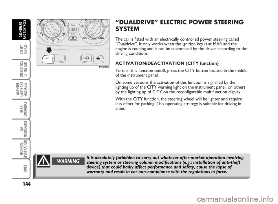
ACTIVATION/DEACTIVATION (CITY function)
To turn this function on/off, press the CITY button located in the middle
of the instrument panel.
On some versions the activation of this function is signalled by the
lighting up of the CITY warning light on the instrument panel, on others
by the lighting up of CITY on the reconfigurable multifunction display.
With the CITY function, the steering wheel will be lighter and require
less effort for parking. This operating strategy is suitable for driving in
cities.
144
SAFETY
DEVICES
CORRECT USE
OF THE CAR
WARNING
LIGHTS AND
MESSAGES
IN AN
EMERGENCY
CAR
MAINTENANCE
TECHNICAL
SPECIFICATIONS
INDEX
DASHBOARD
AND CONTROLS
F0H0122m
WARNINGIt is absolutely forbidden to carry out whatever after-market operation involving
steering system or steering column modifications (e.g.: installation of anti-theft
device) that could badly affect performance and safety, cause the lapse of
warranty and result in car non-compliance with the regulations in force.
Page 146 of 314

FAILURE WARNINGS
Any electric power steering failure is indicated by
cluster warning light gcoming on (together, where
provided, with the message on the reconfigurable
multifunction display - see the “Warning lights”
chapter).
In the event of electric power steering failure, the car
can be driven with mechanical steering to the closest
Fiat Dealership.IMPORTANT The steering may become slightly stiff
following parking manoeuvres including a great deal of
steering. This is normal and caused by the system to
prevent motor overheating. No servicing is required.
The electrical power steering system will return to
normal operation the next time the car is used.
145
SAFETY
DEVICES
CORRECT USE
OF THE CAR
WARNING
LIGHTS AND
MESSAGES
IN AN
EMERGENCY
CAR
MAINTENANCE
TECHNICAL
SPECIFICATIONS
INDEX
DASHBOARD
AND CONTROLS
WARNINGAlways switch the engine off, remove the key from the starting device and actuate
the steering lock before carrying out any maintenance operation, especially when
the wheels are raised from the ground. In case this is not possible (e.g. when the
key must be in MAR position or the engine running), remove the electric power
steering main fuse before carrying out any maintenance operation.
Page 147 of 314

PARKING SENSORS (where provided)
The parking sensors are located on the rear bumper and their function is to
inform the driver, through an intermittent buzzer, about the presence of
obstacles in the rear part of the car.
ACTIVATION
The sensors are automatically activated when the reverse gear is
engaged.
As the distance from the obstacle behind the car decreases, the acoustic
alarm becomes more frequent.
BUZZER WARNINGS
When the reverse gear is engaged an intermittent acoustic signal is
automatically activated.
The acoustic signal:
❒becomes louder as the reduction of distance between the car and the
obstacle decreases;
❒becomes continuous when the distance between the car and the
obstacle is less that 30 cm and stops if the distance raises;
❒is constant if the distance is unvaried. If this situation takes place for
side sensors, the signal is stopped after about 3 seconds to prevent
sound indications when performing manoeuvres near walls.
Direction distances
The central detecting range varies according to car engine type/set-up
version: detection range is 140 cm. For small size obstacles (or in case of
parking deterrent blocks that are round shaped) it is 70 cm. Side
detecting range is 60 cm.
If several obstacles are detected, the control unit indicates the nearest
one.
146
SAFETY
DEVICES
CORRECT USE
OF THE CAR
WARNING
LIGHTS AND
MESSAGES
IN AN
EMERGENCY
CAR
MAINTENANCE
TECHNICAL
SPECIFICATIONS
INDEX
DASHBOARD
AND CONTROLS
F0H0123m