Page 66 of 146
65GETTING TO KNOW YOUR CAR
WIRING DIAGRAM AND ADDITIONAL BRANCHES fig. 86
A- Aerial
B- Radio receiver unit connection
C- Speaker on right dashboard
panel
D- Speaker on left dashboard panel
E- Power supply fuses
F- Power supply with extra fuse for
amplifier installation only (for systems
with 20 + 20W output or higher).
Wire colour coding:
A=light blue - BN=white/black - N=black -
NZ=black/purple - RN=red/black -
RV=red/green - SN=pink/black
F
E
DC
B
B
A
15
ST EQ NL CR
CARD1 2 3 4 5 6 SEARCH SCAN.
22
RN
BNNZ
SN
N RV
A
fig. 86
P4Q00181
001-069 Seicento GB 22-11-2007 10:50 Pagina 65
Page 73 of 146

72DRIVING YOUR CAR
HANDBRAKE
The handbrake lever is between the
front seats.
Pull the handbrake lever upwards
until the car cannot be moved. Four
or five clicks are generally enough
when the car is on level ground while
nine or ten may be required if the car
is on a steep slope or laden. IMPORTANTIf this is not the
case, go to a Fiat Dealership to
have the handbrake adjusted.
Instrument panel warning light x
will come on when the handbrake
lever is pulled up and the ignition key
is at MAR.
To release the handbrake:
1)Slightly lift the hand brake and
press release button A-fig. 1;
2)keep the button pressed in and
lower the lever. Warning light xwill
go out;
3)to prevent accidental movement
of the car, this procedure should be
carried out with the brake pedal
pressed down.
STEERING LOCK LEVER
Use the brake pedal to lock the bot-
tom end. HOW TO USE
THE GEARS
The lever positions for the different
gears are shown in fig. 2(this diagram
is also on the gear knob).
Press the clutch fully.
To put the car in reverse (R), wait
until the car has stopped and, from
neutral: move the lever to the right
and back.
fig. 1
P4Q00078
fig. 2
P4Q00079
070-082 Seicento GB 22-11-2007 10:50 Pagina 72
Page 79 of 146

78DRIVING YOUR CAR
For electrical connection, a 7 or 13
pole 12VDC coupling must be used
(CUNA/UNI and ISO/DIN standards).
Follow the instructions provided by
the manufacturer of the car and/or
the tow hitch.The electrical brake (where relevant)
or other devices (electrical winch,
etc.) must be powered directly from
the battery by means of a lead with a
cross-section area no smaller than
2.5 mm
2. In addition to the electrical
connections, only the power wire foran additional electrical brake and for
internal trailer lighting with a power
not exceeding 15W can be connected
to the car’s electrical system.
The coupling electrical connections
are shown in fig. 4.
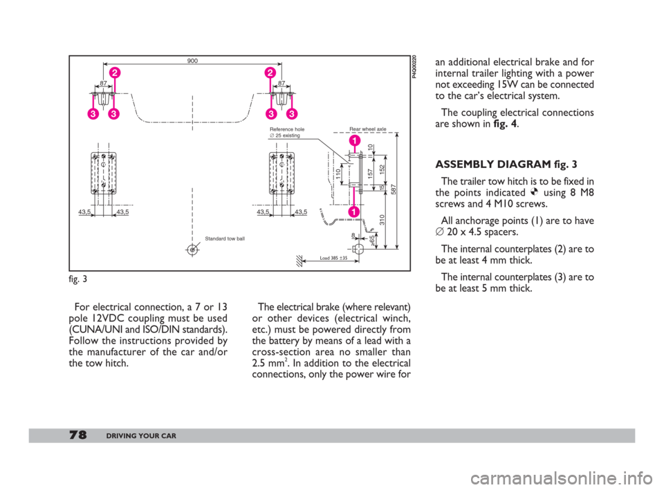
ASSEMBLY DIAGRAM fig. 3
The trailer tow hitch is to be fixed in
the points indicated Øusing 8 M8
screws and 4 M10 screws.
All anchorage points (1) are to have
�’20 x 4.5 spacers.
The internal counterplates (2) are to
be at least 4 mm thick.
The internal counterplates (3) are to
be at least 5 mm thick.
43,5 43,5
15
≥65
3108
152
587110
10 157
43,5 43,5
1
1
87
33
287
33
2
900
fig. 3
P4Q00220
Rear wheel axle
Load 385 ±35
Reference hole
�’25 existing
Standard tow ball
070-082 Seicento GB 22-11-2007 10:50 Pagina 78
Page 80 of 146
79DRIVING YOUR CAR
Fasten the tow hitch to the body
without drilling or trimming the rear
bumper that would be visible when
the tow hitch is removed.
IMPORTANT A clearly visible
plate of a suitable size and made of
suitable material bearing the following:
MAX LOAD ON BALL COUPLING
70 kg.
After assembly, seal the
holes to prevent exhaust
fumes from entering the
vehicle.
E
DCA
B
1
2
3
4 5 6
7
M
N
V
G
R
AN
fig. 4
P4Q00178
A=light blue - G=yellow - M=brown N=black - R=red - V=green
WIRING DIAGRAM fig. 4
A- Seven pole coupling on tow hitch
B- Rear earth wire connection
C- Taillight power connection
D- Rear foglight, brake light and direction indicator connection
E- Electromagnetic brake power connection.
070-082 Seicento GB 22-11-2007 10:50 Pagina 79
Page 141 of 146

140INDEX
– right lever .............................. 38
Storing the car ............................ 82
Sun roof
– electrically operated ........... 43
Sun visors .................................... 43
Suspension ................................... 127
Symbols ........................................ 4
Tank cap
Technical specifications ............ 124
Third brake lights ....................... 96
To the service station ................ 67
Tools ............................................. 86
Top speed .................................... 133
Towing the car .......................... 103
Towing trailers
– fitting diagram ........................ 78
– installation of tow hook ..... 77
– warnings ................................. 77
Transmission ............................... 126
Travelling safely and in harmony
with nature ............................... 4
Tyre inflation pressure ............. 130
Tyres
– changing a wheel ................... 87– inflation pressure ................ 130
– maintenance .......................... 117
– snow tyres ............................. 80
– types ....................................... 130
Usage conditions ..................... 75
Van ............................................. 62
Various controls ........................ 40
Vehicle inactivity ........................ 82
Ventilation ................................... 35
Warning lights ........................ 23
Weights ........................................ 132
Wheel
– maintenance .......................... 117
– replacement .......................... 87
– spare wheel ........................... 128
– types ....................................... 130
Wheel geometry ........................ 128
Windows (cleaning) .................. 122
Windscreen and rearscreen wiper
blades ......................................... 118
Windscreen washer
– controls .................................. 38– fluid level ................................ 112
Windscreen wiper
– blades ...................................... 118
– controls .................................. 38
– jets ........................................... 120
Windscreen/rearscreen
washer fluid level ..................... 112
137-144 Seicento GB 28-11-2007 9:38 Pagina 140