Page 285 of 393

284 Practical hintsDisplay messages
5
The operating system shows warnings,
malfunctions or additional information in
the display.
Certain messages are accompanied by a
warning signal or a permanent tone.
High-priority messages are highlighted in
red in the display.
Please respond in accordance with the
messages and follow the additional notes
in these Operating instructions.
\4Low-priority messages can be acknowl-
edged using theè, ·, j
ork buttons on the steering wheel
or using the reset button on the in-
strument cluster (\2page 84). They are
then stored in the malfunction memo-
ry.
\4Highest-priority messages cannot be
acknowledged and are automatically
stored in the malfunction memory.If you select the Malfunction memory
menu in the operating system
(\2page 95), the acknowledged and
unacknowledged messages will appear.
The following table shows messages which
could appear in the display. The messages
are divided into two types to make it easier
for you to find the relevant message:
\4Text messages are shown in alphabeti-
cal order from (\2page 285) onwards
\4Symbol messages (\2page 289)Display messages on vehicles with
steering wheel buttons
Warning
G
No messages can be displayed if there is a
failure of the instrument cluster and / or the
display. You will not then be able to see in-
formation about the vehicle status, such as
speed and outside temperature, warning
and indicator lamps, malfunction and warn-
ing messages or the failure of systems. Han-
dling characteristics may be affected.
Contact an authorized Sprinter Dealer im-
mediately which has the necessary special-
ist knowledge and tools to carry out the
work required.
The manufacturer recommends that you use
an authorized Sprinter Dealer for this pur-
pose. In particular, work relevant to safety
or on safety-related systems must be car-
ried out at an authorized Sprinter Dealer.
Warning
G
Always have maintenance work carried out
at an authorized Sprinter Dealer which has
the necessary specialist knowledge and
tools to carry out the work required.
The manufacturer recommends that you use
an authorized Sprinter Dealer for this pur-
pose. In particular, work relevant to safety
or on safety-related systems must be car-
ried out at an authorized Sprinter Dealer.
There is a risk of an accident and injury if
this work is carried out incorrectly.
Page 295 of 393

294 Practical hintsDisplay messages
5
.
Additional ind.
lamps
An additional turn signal is malfunction-
ing.
\1Visit an authorized Sprinter Dealer as
soon as possible.
Cornering lamp left
The left-hand cornering lamp* is malfunc-
tioning.
\1Visit an authorized Sprinter Dealer as
soon as possible.
Cornering lamp right
The right-hand cornering lamp* is mal-
functioning.
\1Visit an authorized Sprinter Dealer as
soon as possible.
Trailer turn signal
left
The left-hand turn signal on the trailer is
malfunctioning.
\1Change the bulb as soon as possible.
Trailer turn signal
right
The right-hand turn signal on the trailer is
malfunctioning.
\1Change the bulb as soon as possible.
Trailer tail lamp
A trailer tail lamp or license plate lamp is
malfunctioning.
\1Change the bulb as soon as possible.
Switch off lights
You have forgotten to switch off the lights
when leaving the vehicle.
\1Switch off the lights.
Lights on automatic.
Remove key
Automatic headlamp mode is active
(\2page 78). The key is in the ignition
lock and the driver’s door is open.
\1Remove the key.
I
Replace key
Visit
workshop
The authorization to drive must be
checked.
\1Visit an authorized Sprinter Dealer.
Display symbol
Display message
Possible cause / result
Possible solution
Page 303 of 393

302 Practical hintsWhere will I find...?
5
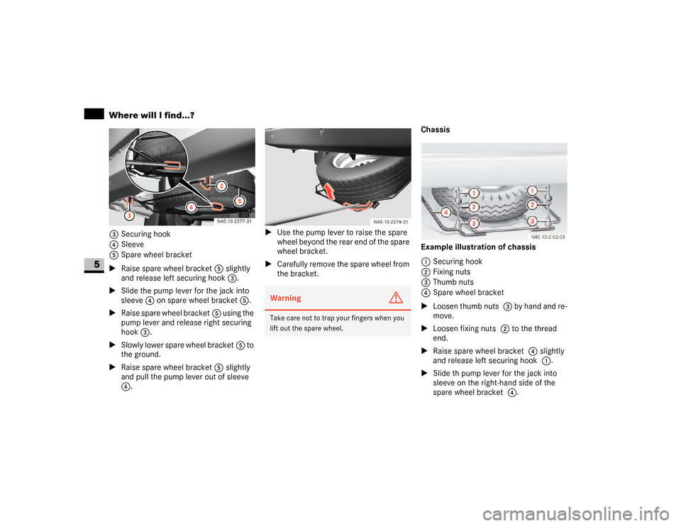
3Securing hook
4Sleeve
5Spare wheel bracket
\1Raise spare wheel bracket5 slightly
and release left securing hook3.
\1Slide the pump lever for the jack into
sleeve4 on spare wheel bracket5.
\1Raise spare wheel bracket5 using the
pump lever and release right securing
hook3.
\1Slowly lower spare wheel bracket5 to
the ground.
\1Raise spare wheel bracket5 slightly
and pull the pump lever out of sleeve
4.\1Use the pump lever to raise the spare
wheel beyond the rear end of the spare
wheel bracket.
\1Carefully remove the spare wheel from
the bracket.Chassis
Example illustration of chassis
1Securing hook
2Fixing nuts
3Thumb nuts
4Spare wheel bracket
\1Loosen thumb nuts 3 by hand and re-
move.
\1Loosen fixing nuts 2 to the thread
end.
\1Raise spare wheel bracket 4 slightly
and release left securing hook 1.
\1Slide th pump lever for the jack into
sleeve on the right-hand side of the
spare wheel bracket 4.
Warning
G
Take care not to trap your fingers when you
lift out the spare wheel.
Page 304 of 393

303 Practical hints
Where will I find...?
5
\1Raise spare wheel bracket 4 using
the pump lever and release right secur-
ing hook 1.
\1Slowly lower spare wheel bracket 4
to the ground.
\1Raise spare wheel bracket 4 slightly
and pull the pump lever out of sleeve.
\1Use the pump lever to raise the spare
wheel beyond the rear end of the spare
wheel bracket.
\1Carefully remove the spare wheel from
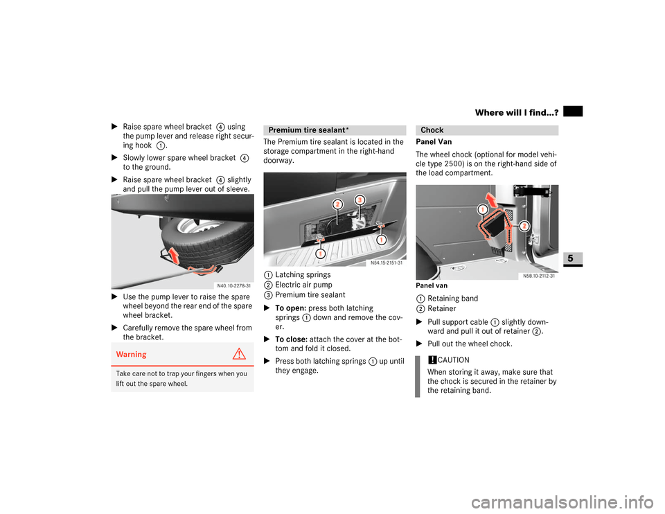
the bracket.The Premium tire sealant is located in the
storage compartment in the right-hand
doorway.
1Latching springs
2Electric air pump
3Premium tire sealant
\1To open: press both latching
springs1 down and remove the cov-
er.
\1To close: attach the cover at the bot-
tom and fold it closed.
\1Press both latching springs1 up until
they engage.Panel Van
The wheel chock (optional for model vehi-
cle type 2500) is on the right-hand side of
the load compartment.
Panel van1Retaining band
2Retainer
\1Pull support cable 1 slightly down-
ward and pull it out of retainer 2.
\1Pull out the wheel chock.
Warning
G
Take care not to trap your fingers when you
lift out the spare wheel.
Premium tire sealant*
Chock!
CAUTION
When storing it away, make sure that
the chock is secured in the retainer by
the retaining band.
Page 307 of 393

306 Practical hintsChanging bulbs
5
\3 Changing bulbsBulbs and lights are an important aspect of
vehicle safety. For this reason, make sure
that all bulbs are in working order at all
times.
\4Switch off the lights to avoid a short cir-
cuit.
\4Only touch new bulbs with a clean lint-
free cloth or something similar. Do not
work with wet or greasy fingers.
\4Only fit 12 V bulbs of the same type as
before and of the correct wattage.
\4Have the headlamp setting checked
regularly.\4If the newly installed bulb does not light
up either, visit an authorized Sprinter
Dealer.
\4Have the following LEDs and bulbs
changed at an authorized Sprinter
Dealer:
\4The additional turn signals in the
exterior mirrors
\4The third brake lamp (cargo and
passenger vans only)*
\4The bi-xenon headlamps*
\4The foglamps* Before changing bulbs
Warning
G
Bulbs and bulb holders can become very
hot. For this reason, allow the light to cool
down before changing the bulb.
Keep bulbs out of the reach of children.
Never use a bulb which has been dropped.
Such a bulb may explode and injure you.
H7 bulbs are pressurized and may explode
when changed. You should therefore wear
eye protection and gloves when you are
changing them.
Page 308 of 393

307 Practical hints
Changing bulbs
5
\1Switch off the lighting.
\1Open the hood (\2page 185).
Bi-xenon headlamps*
High-beam headlamps, low-beam head-
lamps
1Catches
2Housing cover
Front bulbs
Bulb
Model
1
Additional turn signal
PY 16 W
2
Turn signal
PY 21 W
3
Halogen headlamp:
low-beam headlamp
H7 55 W
Bi-xenon headlamp*:
low-beam headlamp /
high-beam headlamp
D1S-35 W
4
Halogen headlamp:
high-beam headlamp
H7 55 W
Cornering lamp*
(Canada only)
H7 55 W
5
Foglamp*
H11 55 W
6
Parking lamp/side
marker/standing
lamp (Canada only)
WY 5 W
Warning
G
Xenon bulbs carry a high voltage. You could
receive a serious or fatal electric shock if
you touch the electrical contacts on the xe-
non bulbs. Do not remove housing cover 2
(\2page 307) if the headlamps are xenon
headlamps.
Bulb
Model
Do not change xenon bulbs yourself.
Instead, always have them changed at an
authorized Sprinter Dealer which has the
necessary specialist knowledge and tools to
carry out the work required.
The manufacturer recommends that you use
an authorized Sprinter Dealer for this pur-
pose. In particular, work relevant to safety
or on safety-related systems must be car-
ried out at an authorized Sprinter Dealer.
Page 311 of 393
310 Practical hintsChanging bulbs
5
Changing the rear bulbs
(van / crewbus)
\1Switch off the lighting.
Rear lamp units
1Securing screws
\1Undo screws1 and remove the rear
lamp unit in the direction of the arrow.
\1Remove the connector.2Retaining lugs
3Brake lamp
4Side marker, Standing lamp (Canada
only), tail lamp
5Reverse lamp
6Turn signal lamp
7Rear foglamp (driver’s side)
\1Release retaining lugs2 and remove
the bulb holder from the rear lamp unit.
\1Press down on the bulb, turn it counter-
clockwise and remove it from the
holder.\1Press the new bulb into the bulb holder
and screw it in clockwise.
\1Plug the connectors into the bulb
holder.
\1Fit the rear lamp unit.
To do this, clip the bulb holder into the
three holes provided on the side and
tighten screws1.
Changing the rear bulbs (chassis)
Example illustration of chassis1Securing screws
2Lens
3Perimeter lamp, side marker
4Turn signal lamp
5Brake lamp
Page 312 of 393
311 Practical hints
Changing bulbs
5
6Tail lamp
7Rear foglamp (driver’s side)
8License plate lamp
9Reverse lamp
\1Switch off the lighting.
\1Undo screws1 and remove lens 2.
\1Press the bulb into the bulb holder and
screw it out in a counterclockwise di-
rection.
\1Press the new bulb into the bulb holder
and screw it in clockwise.
\1Replace lens2 and retighten
screws1.\1Switch off the lighting.
Identification lamps W 5 W (cab chas-
sis only)
\1Switch off the lighting.
\1Undo screws 1 and remove lamp hou-
sing.\1Turn the bulb holder 2and remove it
together with the bulb.
\1Pull the bulb out of the bulb holder 2.
\1Press the new bulb into the bulb holder
2.
\1Screw the bulb holder 2 containing
the bulb into the lamp housing.
\1Carefully reattach the lamp housing
and retighten screws 1.
Changing additional bulbs
1Securing screws
2Bulb holder