2007 CHRYSLER 300 LX seats
[x] Cancel search: seatsPage 153 of 432

STORAGE
Console Features
The center console contains a large storage bin. The
storage bin contains a four-slot coin holder (designed to
hold various size coins) and a rubber mat at the bottom of
the bin for noise control. The bin is large enough to hold
a portable AC/DC converter to power laptops, games, or
other electrical equipment. Two slots at the top right side
of the bin provide clearance for power cords to pass
conveniently out of the bin with the lid closed. This
feature is ideal for games, laptops, cell phones, or other
electrical equipment. The console’s front-opening lid
allows for easy access to the storage bin for the both the
driver and the front passenger. The inside portion of the
arm rest lid contains a penholder, a tissue holder, and a
tire gauge holder.In addition to the internal storage, the console contains
two shift bezel cubby bins with rubber mats for holding
small items. For vehicles not equipped with navigation
radio, the console also contains an extra storage bin
located below the climate control, which holds up to four
CD jewel cases.
Cargo Area
The 60/40 split-folding rear seat provides cargo-carrying
versatility. The seatbacks fold down easily by pulling
nylon tabs between the seatbacks and the bolsters. When
the seats are folded down, they provide a continuous,
nearly flat extension of the load floor.
When the seatback is folded to the upright position, make
sure it is latched by strongly pulling on the top of the
seatback above the seat strap.
UNDERSTANDING THE FEATURES OF YOUR VEHICLE 153
3
ProCarManuals.com
Page 154 of 432

WARNING!
•Be certain that the seatback is securely locked into
position. If the seatback in not securely locked
into position, the seat will not provide the proper
stability for child seats and/or passengers. An
improperly latched seat could cause serious in-
jury.
•The cargo area in the rear of the vehicle (with the
rear seatbacks in the locked-up or folded down
position) should not be used as a play area by
children when the vehicle is in motion. They
could be seriously injured in an accident. Chil-
dren should be seated and using the proper re-
straint system.
•To help protect against personal injury, passen-
gers should not be seated in the rear cargo area.
The rear cargo space is intended for load carrying
purposes only, not for passengers, who should sit
in seats and use seat belts.
WARNING!
•The weight and position of cargo and passengers
can change the vehicle center of gravity and
vehicle handling. To avoid loss of control result-
ing in personal injury, follow these guidelines for
loading your vehicle:
•Always place cargo evenly on the cargo floor. Put
heavier objects as low and as far forward as possible.
•Place as much cargo as possible in front of the rear
axle. Too much weight or improperly placed weight
over or behind the rear axle can cause the rear of the
vehicle to sway.
•Do not pile luggage or cargo higher than the top of the
seatback. This could impair visibility or become a
dangerous projectile in a sudden stop or collision.
154 UNDERSTANDING THE FEATURES OF YOUR VEHICLE
ProCarManuals.com
Page 174 of 432

•ACC Ready — When the Adaptive Cruise Control
(ACC) system is activated. Refer to “Adaptive Cruise
Control (ACC)” in Section 3 of this manual for detailed
information (if so equipped).
•ACC Set — After setting the desired speed in the
Adaptive Cruise Control (ACC) system. Refer to
“Adaptive Cruise Control (ACC)” in Section 3 of this
manual for detailed information (if so equipped).
•Driver Override — If you apply the accelerator after
setting the desired speed in the Adaptive Cruise
Control (ACC) system. Refer to “Adaptive Cruise
Control (ACC)” in Section 3 of this manual for detailed
information (if so equipped).
•Distance Set — After changing the desired following
distance in the Adaptive Cruise Control (ACC) system,
this message will display momentarily. Refer to
“Adaptive Cruise Control (ACC)” in Section 3 of this
manual for detailed information (if so equipped).
•Attention — If the Adaptive Cruise Control (ACC)
system predicts that its maximum braking level is not
sufficient to maintain the set distance, this messagewill flash and a chime will sound while ACC continues
to apply its maximum braking capacity. When this
occurs, you should immediately apply the brakes as
needed to maintain a safe distance from the vehicle
ahead. Refer to “Adaptive Cruise Control (ACC)” in
Section 3 of this manual for detailed information (if so
equipped).
•ACC Unavailable — If the Adaptive Cruise Control
(ACC) system deactivates due to performance limiting
conditions. Refer to “Adaptive Cruise Control (ACC)”
in Section 3 of this manual for detailed information (if
so equipped).
•Service ACC — If the Adaptive Cruise Control (ACC)
system turns off due to an internal system fault that
requires service from an authorized dealer. Refer to
“Adaptive Cruise Control (ACC)” in Section 3 of this
manual for detailed information (if so equipped).
•Adjustable Pedals Disabled – Cruise Engaged (with a
single chime) — only available on vehicles equipped
with memory seats.
174 UNDERSTANDING YOUR INSTRUMENT PANEL
ProCarManuals.com
Page 175 of 432

•Adjustable Pedals Disabled – Vehicle In Reverse (with
a single chime) — only available on vehicles equipped
with memory seats.
•Channel 1, 2, OR 3 Transmit
•Channel 1, 2, OR 3 Training
•Channel 1, 2, OR 3 Trained
•Clearing Channels
•Channels Cleared
•Channels Defaulted
•Did Not Train
•Left Front Low Pressure (with a single chime). Refer to
information on “Tire Pressure” and “Tire Pressure
Monitor” in the “Starting And Operating” section of
this manual.
•Left Rear Low Pressure (with a single chime). Refer to
information on “Tire Pressure” and “Tire Pressure
Monitor” in the “Starting And Operating” section of
this manual.
•Right Front Low Pressure (with a single chime). Refer
to information on “Tire Pressure” and “Tire Pressure
Monitor” in the “Starting And Operating” section of
this manual.
•Right Rear Low Pressure (with a single chime). Refer
to information on “Tire Pressure” and “Tire Pressure
Monitor” in the “Starting And Operating” section of
this manual.
•Check TPM System (with a single chime). Refer to
information on “Tire Pressure Monitor” in the “Start-
ing And Operating” section of this manual.
•Check Gascap (refer to “Adding Fuel” in Section 5 of
this manual for more details)
•Service Park Assist System (with a single chime)
Trip Functions
Press and release the MENU button until one of the
following Trip Functions displays in the EVIC:
•Average Fuel Economy / Fuel Saver Mode
•Distance To Empty
UNDERSTANDING YOUR INSTRUMENT PANEL 175
4
ProCarManuals.com
Page 220 of 432

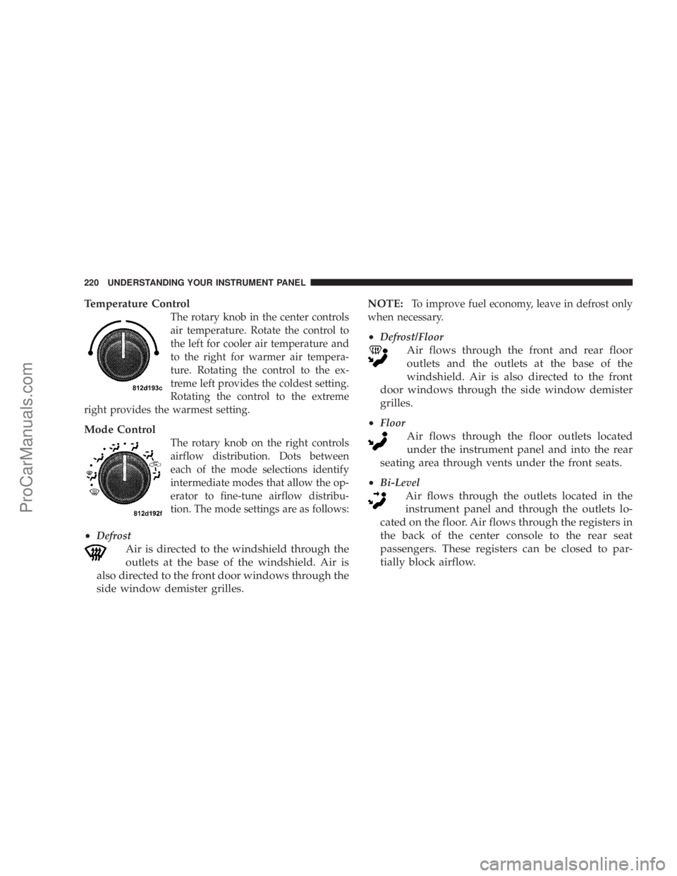
Temperature Control
The rotary knob in the center controls
air temperature. Rotate the control to
the left for cooler air temperature and
to the right for warmer air tempera-
ture. Rotating the control to the ex-
treme left provides the coldest setting.
Rotating the control to the extreme
right provides the warmest setting.
Mode Control
The rotary knob on the right controls
airflow distribution. Dots between
each of the mode selections identify
intermediate modes that allow the op-
erator to fine-tune airflow distribu-
tion. The mode settings are as follows:
•Defrost
Air is directed to the windshield through the
outlets at the base of the windshield. Air is
also directed to the front door windows through the
side window demister grilles.NOTE:
To improve fuel economy, leave in defrost only
when necessary.
•Defrost/Floor
Air flows through the front and rear floor
outlets and the outlets at the base of the
windshield. Air is also directed to the front
door windows through the side window demister
grilles.
•
Floor
Air flows through the floor outlets located
under the instrument panel and into the rear
seating area through vents under the front seats.
•
Bi-Level
Air flows through the outlets located in the
instrument panel and through the outlets lo-
cated on the floor. Air flows through the registers in
the back of the center console to the rear seat
passengers. These registers can be closed to par-
tially block airflow.
220 UNDERSTANDING YOUR INSTRUMENT PANEL
ProCarManuals.com
Page 225 of 432

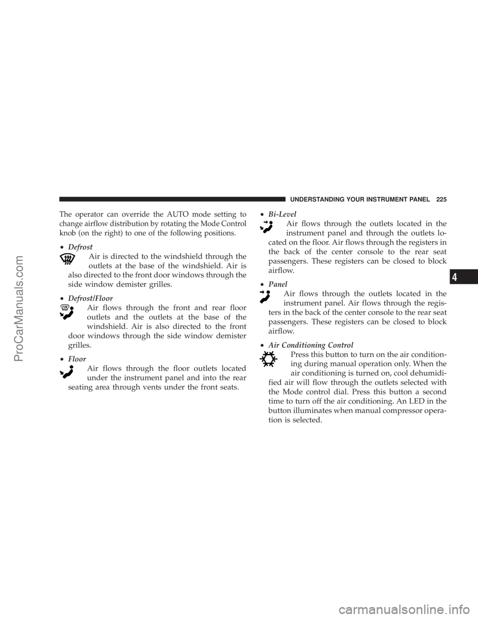
The operator can override the AUTO mode setting to
change airflow distribution by rotating the Mode Control
knob (on the right) to one of the following positions.
•Defrost
Air is directed to the windshield through the
outlets at the base of the windshield. Air is
also directed to the front door windows through the
side window demister grilles.
•
Defrost/Floor
Air flows through the front and rear floor
outlets and the outlets at the base of the
windshield. Air is also directed to the front
door windows through the side window demister
grilles.
•
Floor
Air flows through the floor outlets located
under the instrument panel and into the rear
seating area through vents under the front seats.•
Bi-Level
Air flows through the outlets located in the
instrument panel and through the outlets lo-
cated on the floor. Air flows through the registers in
the back of the center console to the rear seat
passengers. These registers can be closed to block
airflow.
•
Panel
Air flows through the outlets located in the
instrument panel. Air flows through the regis-
ters in the back of the center console to the rear seat
passengers. These registers can be closed to block
airflow.
•
Air Conditioning Control
Press this button to turn on the air condition-
ing during manual operation only. When the
air conditioning is turned on, cool dehumidi-
fied air will flow through the outlets selected with
the Mode control dial. Press this button a second
time to turn off the air conditioning. An LED in the
button illuminates when manual compressor opera-
tion is selected.
UNDERSTANDING YOUR INSTRUMENT PANEL 225
4
ProCarManuals.com
Page 367 of 432

Cavity Car-
tridge
FuseMini
FuseDescription
1 60 Amp
Yellow— Ignition Off Draw (IOD)
2 40 Amp
Green— Battery
3———
4 40 Amp
Green— Battery
5 30 Amp
Pink— Heated Seats - if
equipped
6 — 20 Amp
YellowFuel Pump
7———
8 — 15 Amp
BlueIgnition Switch/Airbag
Control Module (ACM)
9 — 20 Amp
YellowConsole Power Outlet
10———
11*———
12*———Cavity Car-
tridge
FuseMini
FuseDescription
13*———
14 — 10 Amp
RedAC Heater Control/
Cluster/Sentry Key Re-
mote Keyless Entry
15 — 20 Amp
YellowTrailer Tow Brake Mod-
ule - if equipped
16———
17 — 20 Amp
YellowCluster
18 — 20 Amp
YellowSelectable Power Outlet
19 — 10 Amp
RedStop Lights
20———
21———
22———
23———
24———
25———
MAINTAINING YOUR VEHICLE 367
7
ProCarManuals.com
Page 369 of 432

Cavity Car-
tridge
FuseMini
FuseDescription
39 — 10 Amp
RedHeated Mirrors - if
equipped
40 — 5 Amp
OrangeHeated Seats - if
equipped/Inside Rear-
view Mirror
41 — 10 Amp
RedAC Heater Control/Park
Assist - if equipped/Tire
Pressure Monitoring - if
equipped
42 30 Amp
Pink— Front Blower Motor
43 30 Amp
Pink— Amplifier - if equipped/
Antenna/Rear Defrost
44 20 Amp
Blue— Amplifier - if equipped/
Front Control Module
(FCM)/Sunroof - if
equipped*Cavities 11, 12, and 13 contain self-resetting fuses (circuit
breakers) that are only serviceable by an authorized
dealer. The Cluster (without power memory seat), the
Driver Seat Switch (with power memory seat), and the
Memory Module (if equipped) are fused by the 25 amp
circuit breaker in Cavity 11. The Passenger Seat Switch is
fused by the 25 amp circuit breaker in Cavity 12. The
Door Modules (except base), the Driver Door Lock
Switch (base), the Driver Express Power Window Switch
(if equipped), and the Passenger Door Lock Switch (base)
are fused by the 25 amp circuit breaker in Cavity 13. If
you experience temporary or permanent loss of these
systems, see your authorized dealer for service.
MAINTAINING YOUR VEHICLE 369
7
ProCarManuals.com