Page 87 of 574
Adding Equipment to Your
Airbag-Equipped Vehicle
Q:Is there anything I might add to the front
or sides of the vehicle that could keep the
airbags from working properly?
A:Yes. If you add things that change your
vehicle’s frame, bumper system, height,
front end or side sheet metal, they may keep
the airbag system from working properly.
Also, the airbag system may not work properly
if you relocate any of the airbag sensors. If
you have any questions about this, you should
contact Customer Assistance before you
modify your vehicle. The phone numbers and
addresses for Customer Assistance are in
Step Two of the Customer Satisfaction
Procedure in this manual. SeeCustomer
Satisfaction Procedure on page 538.
Q:Because I have a disability, I have to get
my vehicle modi�ed. How can I �nd out
whether this will affect my airbag system?
A:Changing or moving any parts of the
front seats, safety belts, the airbag sensing
and diagnostic module, steering wheel,
instrument panel, the inside review mirror,
ceiling headliner, ceiling and pillar garnish trim,
roof-mounted airbag modules, or airbag
wiring can affect the operation of the airbag
system. If you have questions, call Customer
Assistance. The phone numbers and
addresses for Customer Assistance are in
Step Two of the Customer Satisfaction
Procedure in this manual. SeeCustomer
Satisfaction Procedure on page 538.
87
Page 104 of 574
Liftgate/Liftglass
{CAUTION:
It can be dangerous to drive with the
liftgate or liftglass open because carbon
monoxide (CO) gas can come into your
vehicle. You cannot see or smell CO. It
can cause unconsciousness and even
death. If you must drive with the liftgate
open or if electrical wiring or other cable
connections must pass through the seal
between the body and the liftgate or
liftglass:
Make sure all other windows are shut.
Turn the fan on your climate control
system to its highest speed and select
the control setting that will force
outside air into your vehicle. See
“Climate Control System” in the Index.
If you have air outlets on or under the
instrument panel, open them all the
way. SeeEngine Exhaust on page 130.
Liftgate Release
To unlock the liftgate, use the power door lock
switch or the remote keyless entry transmitter. See
Remote Keyless Entry (RKE) System Operation
on page 96. The liftglass will also unlock when the
liftgate is unlocked.
Press the button on the liftglass to open it. To
open the entire liftgate, lift the handle located in
the center of the liftgate. When the liftgate is
opened, the liftglass will lock after a short delay.
Emergency Release for Opening
Liftgate
1. Remove the trim plug, located on the inside of
the liftgate in the center, to expose the access
hole in the trim panel.
2. Use a tool to reach through the access hole in
the trim panel.
3. Pry the left release lever up to the unlock
position. Pry the right release lever up to
unlatch the liftgate.
4. Reinstall the trim plug.
104
Page 174 of 574
Turn and Lane-Change Signals
The turn signal has two upward (for right) and
two downward (for left) positions. These positions
let you signal a turn or a lane change.
To signal a turn, move the lever all the way up
or down. When the turn is �nished, the lever
returns automatically.
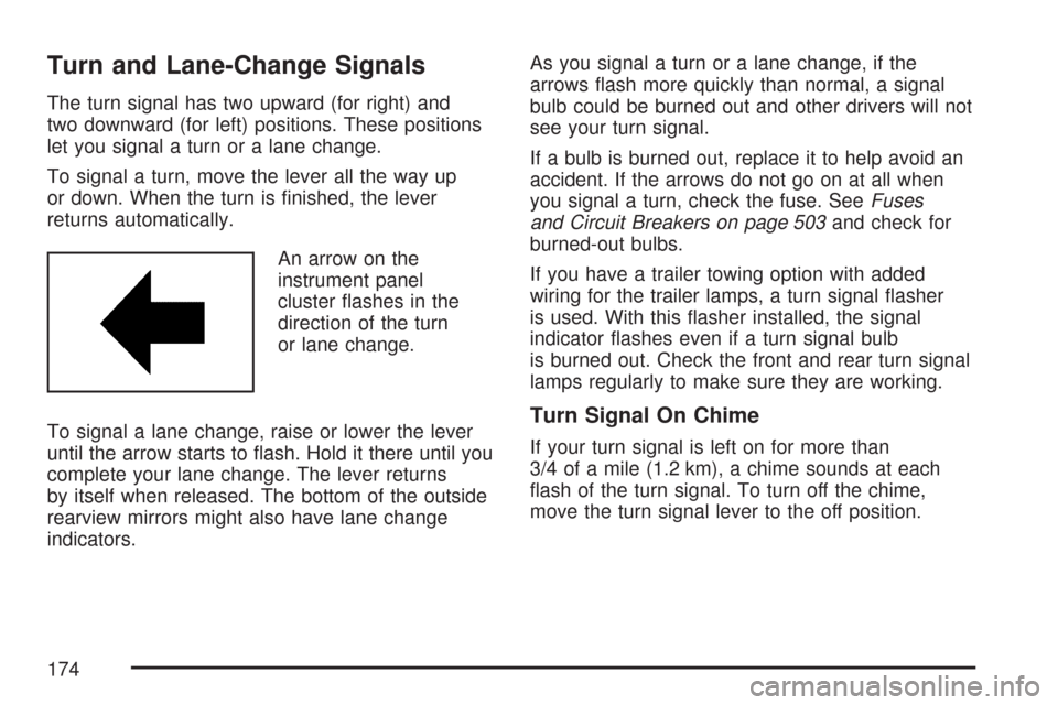
An arrow on the
instrument panel
cluster �ashes in the
direction of the turn
or lane change.
To signal a lane change, raise or lower the lever
until the arrow starts to �ash. Hold it there until you
complete your lane change. The lever returns
by itself when released. The bottom of the outside
rearview mirrors might also have lane change
indicators.As you signal a turn or a lane change, if the
arrows �ash more quickly than normal, a signal
bulb could be burned out and other drivers will not
see your turn signal.
If a bulb is burned out, replace it to help avoid an
accident. If the arrows do not go on at all when
you signal a turn, check the fuse. SeeFuses
and Circuit Breakers on page 503and check for
burned-out bulbs.
If you have a trailer towing option with added
wiring for the trailer lamps, a turn signal �asher
is used. With this �asher installed, the signal
indicator �ashes even if a turn signal bulb
is burned out. Check the front and rear turn signal
lamps regularly to make sure they are working.
Turn Signal On Chime
If your turn signal is left on for more than
3/4 of a mile (1.2 km), a chime sounds at each
�ash of the turn signal. To turn off the chime,
move the turn signal lever to the off position.
174
Page 202 of 574
Passenger Safety Belt
Reminder Light
Several seconds after the key is turned to RUN or
START, a chime will sound for several seconds
to remind the front passenger to buckle their
safety belt. This would only occur if the passenger
airbag is enabled. SeePassenger Sensing
System on page 80for more information. The
passenger safety belt light will also come on
and stay on for several seconds, then it will
�ash for several more.
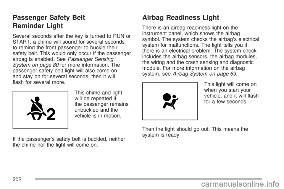
This chime and light
will be repeated if
the passenger remains
unbuckled and the
vehicle is in motion.
If the passenger’s safety belt is buckled, neither
the chime nor the light will come on.
Airbag Readiness Light
There is an airbag readiness light on the
instrument panel, which shows the airbag
symbol. The system checks the airbag’s electrical
system for malfunctions. The light tells you if
there is an electrical problem. The system check
includes the airbag sensors, the airbag modules,
the wiring and the crash sensing and diagnostic
module. For more information on the airbag
system, seeAirbag System on page 69.
This light will come on
when you start your
vehicle, and it will �ash
for a few seconds.
Then the light should go out. This means the
system is ready.
202
Page 381 of 574
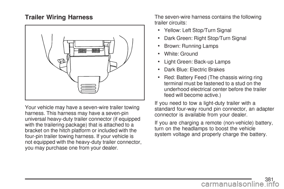
Trailer Wiring Harness
Your vehicle may have a seven-wire trailer towing
harness. This harness may have a seven-pin
universal heavy-duty trailer connector (if equipped
with the trailering package) that is attached to a
bracket on the hitch platform or included with the
four-pin trailer towing harness. If your vehicle is
not equipped with the heavy-duty trailer connector,
you may purchase one from your dealer.The seven-wire harness contains the following
trailer circuits:
Yellow: Left Stop/Turn Signal
Dark Green: Right Stop/Turn Signal
Brown: Running Lamps
White: Ground
Light Green: Back-up Lamps
Dark Blue: Electric Brakes
Red: Battery Feed (The chassis wiring ring
terminal must be fastened to a stud on the
underhood electrical center before the trailer
feed will become active.)
If you need to tow a light-duty trailer with a
standard four-way round pin connector, an adapter
connector is available from your dealer.
If you are charging a remote (non-vehicle) battery,
turn on the headlamps to boost the vehicle
system voltage and properly charge the battery.
381
Page 382 of 574
Your vehicle is also equipped with wiring for an
electric trailer brake controller. These wires
are located inside the vehicle on the driver’s side
under the instrument panel. These wires should
be connected to an electric trailer brake controller
by your dealer or a quali�ed service center.
Your vehicle may be equipped with a four-pin
trailer towing harness. This harness has a four-pin
trailer connector that contains the following
trailer circuits:
Yellow: Left Stop/Turn Signal
Dark Green: Right Stop/Turn Signal
Brown: Running Lamps
White: GroundThis harness also contains the following trailer
circuits that are not connected to the four-pin trailer
connector:
Light Green: Back-Up Lamps
Dark Blue: Electric Brakes
Red: Battery Feed
If your vehicle is a TrailBlazer SS, you were
provided with a trailer wiring harness extension,
and instructions for installing this extension, when
your vehicle was delivered. This extension will
allow your vehicle’s trailer wiring harness to
be more easily accessible. There is a four-way
connector on the harness. A seven-way adapter
plug is also included in case your trailer requires it.
382
Page 443 of 574
4. Unclip the wiring harness (A) and remove the
three retaining screws (B) from the socket
plate.
5. Remove the socket plate.6. Holding the socket, pull the bulb to release it
from the socket.
7. Push the new bulb into the socket until it
clicks.
8. Reinstall the socket and tighten the
three screws.
9. Reconnect the wiring harness.
10. Reinstall the taillamp assembly by lining up
the locator pins with the retainers in the
vehicle’s body.
11. Reinstall the two screws and tighten.
12. Close the liftgate.
443
Page 502 of 574
Electrical System
Add-On Electrical Equipment
Notice:Do not add anything electrical to your
vehicle unless you check with your dealer
�rst. Some electrical equipment can damage
your vehicle and the damage would not
be covered by your warranty. Some add-on
electrical equipment can keep other
components from working as they should.
Add-on equipment can drain your vehicle’s battery,
even if your vehicle is not operating.
Your vehicle has an airbag system. Before
attempting to add anything electrical to your
vehicle, seeServicing Your Airbag-Equipped
Vehicle on page 86.
Headlamps
The headlamp wiring is protected by four fuses.
An electrical overload will cause a lamp to go
on and off. If this happens, have your headlamp
wiring checked right away.
Windshield Wiper Fuses
The windshield wiper motor is protected by a
circuit breaker and a fuse. If the motor overheats
due to heavy snow or ice, the wiper will stop
until the motor cools. If the overload is caused by
some electrical problem, be sure to get it �xed.
Power Windows and Other
Power Options
Circuit breakers protect the power windows and
other power accessories. When the current load is
too heavy, the circuit breaker opens and closes,
protecting the circuit until the problem is �xed
or goes away.
502