2007 BMW MOTORRAD K 1200 S brake light
[x] Cancel search: brake lightPage 4 of 166

Table of ContentsYou can also consult the index at
the end of this Rider's Manual if
you want to find a particular topic
or item of information.
1 General instructions . . . . . 5
Overview . . . . . . . . . . . . . . . . . . . . . . 6
Abbreviations and symbols . . . . 6
Equipment . . . . . . . . . . . . . . . . . . . . 7
Technical data . . . . . . . . . . . . . . . . 7
Currency . . . . . . . . . . . . . . . . . . . . . . 7
2 General views . . . . . . . . . . . . . 9
General view, left side . . . . . . . . 11
General view, right side . . . . . . 13
Underneath the seat . . . . . . . . . 14
Handlebar fitting, left . . . . . . . . . 15
Handlebar fitting, right . . . . . . . . 16
Instrument cluster . . . . . . . . . . . . 17
Headlight . . . . . . . . . . . . . . . . . . . . . 183 Status indicators . . . . . . . 19
Standard status
indicators . . . . . . . . . . . . . . . . . . . . . 20
Status indicators with on-
board computer
OE
........... 21
Status indicators with
tyre-pressure monitoring
(RDC)
OE...................... 22
Standard warnings . . . . . . . . . . . 22
Warnings issued by the on-
board computer
OE
........... 27
ABS warnings . . . . . . . . . . . . . . . . 29
ASC warnings
OE
............. 31
RDC warnings
OE
............. 33
Anti-theft alarm
warnings
OE................... 38
4 Operation . . . . . . . . . . . . . . . . 41
Ignition switch and steering
lock . . . . . . . . . . . . . . . . . . . . . . . . . . 42
Electronic immobiliser . . . . . . . . 43
Clock . . . . . . . . . . . . . . . . . . . . . . . . . 44
Odometer and tripmeters . . . . 45
On-board computer
OE
....... 47 Tyre pressure monitoring
RDC
OE
....................... 51
Lights . . . . . . . . . . . . . . . . . . . . . . . . 52
Turn indicators . . . . . . . . . . . . . . . 53
Hazard warning flashers . . . . . . 53
Emergency off switch (kill
switch) . . . . . . . . . . . . . . . . . . . . . . . 54
Grip heating
OE
............... 55
Automatic Stability Control
ASC
OE
....................... 55
Clutch . . . . . . . . . . . . . . . . . . . . . . . . 56
Brakes . . . . . . . . . . . . . . . . . . . . . . . 57
Mirrors . . . . . . . . . . . . . . . . . . . . . . . 58
Spring preload . . . . . . . . . . . . . . . 58
Damping . . . . . . . . . . . . . . . . . . . . . 59
Electronic Suspension Ad-
justment ESA
OE
............. 59
Tyres . . . . . . . . . . . . . . . . . . . . . . . . . 62
Headlight . . . . . . . . . . . . . . . . . . . . . 62
Seat . . . . . . . . . . . . . . . . . . . . . . . . . . 63
Helmet holder . . . . . . . . . . . . . . . . 65
Luggage loops . . . . . . . . . . . . . . . 66
Page 28 of 166
If the battery is not char-
ging, continuing to ride can
cause it to discharge completely,
in which case it will suffer irrepar-
able damage.
If possible, do not continue your
journey.
Battery is not being charged.
You can continue to ride until
the battery is discharged. Bear
in mind, however, that the en-
gine could cut out suddenly
and that the battery could dis-
charge until completely flat,
in which case it might have
suffered irreparable damage.
Have the fault rectified as
quickly as possible by a
specialist workshop, preferably
an authorised BMW Motorrad
dealer.
Rear light bulb defective General warning light shows
yellow.
LAMPR !
appears on the dis-
play.
A defective bulb places
your safety at risk because
it is easier for other users to
oversee the motorcycle.
Replace defective bulbs as
soon as possible; always carry a
complete set of spare bulbs if
possible.
Rear light or brake light bulb de-
fective.
Replacing brake light and rear
light bulb ( 120)
Front light bulb defective
LAMPF !
appears on the dis-
play.
A defective bulb places
your safety at risk because
it is easier for other users to
oversee the motorcycle.
Replace defective bulbs as
soon as possible; always carry a complete set of spare bulbs if
possible.
Low-beam headlight, high-beam
headlight, side-light or turn-indic-
ator bulb defective.
Replacing low-beam headlight
bulb ( 116)
Replacing high-beam headlight
bulb ( 118)
Replacing parking-light bulb
( 119)
Replacing front turn indicator
bulbs ( 122)
Replacing rear turn indicator
bulbs ( 123)
Bulbs defective General warning light shows
yellow.
LAMPS !
appears on the dis-
play.
A defective bulb places
your safety at risk because
it is easier for other users to
oversee the motorcycle.
326zStatus indicators
Page 43 of 166
Operation
Operation
Ignition switch and steering lock..... 42
Electronic immobiliser . . . ............ 43
Clock ................................ 44
Odometer and tripmeters ............ 45
On-board computer
OE
............... 47
Tyre pressure monitoring
RDC
OE
.............................. 51
Lights ................................ 52
Turn indicators ....................... 53
Hazard warning flashers . . ............ 53
Emergency off switch (kill switch) . . . . 54
Grip heating
OE
....................... 55
Automatic Stability Control
ASC
OE
.............................. 55
Clutch ............................... 56 Brakes . .
............................. 57
Mirrors . . ............................. 58
Spring preload ....................... 58
Damping ............................. 59
Electronic Suspension Adjustment
ESA
OE
............................... 59
Tyres . . . ............................. 62
Headlight ............................ 62
Seat ................................. 63
Helmet holder ....................... 65
Luggage loops ....................... 66
441zOperation
Page 72 of 166
ChecklistUse the following checklist to
check important functions, set-
tings and wear limits before you
ride off.Brakes
Brake-fluid levels, front and rear
Clutch
Clutch fluid level
Shock absorber setting and
spring preload
Tyre-tread depth and tyre
pressures
Cases correctly installed and
luggage secured
At regular intervals: Engine oil level (every refuelling
stop)
Brake-pad wear (every third
refuelling stop)
StartingSide standYou cannot start the motorcycle
with the side stand extended and
a gear engaged. The engine will
switch itself off if you start it with
the gearbox in neutral and then
engage a gear before retracting
the side stand.GearboxYou can start the engine when
the gearbox is in neutral or if you
pull the clutch with a gear en-
gaged. Do not pull the clutch un-
til after you have switched on the
ignition, as otherwise the engine
will refuse to start. When the
gearbox is in neutral, the green
neutral telltale light is on and the
gear indicator in the multifunction
display shows N.
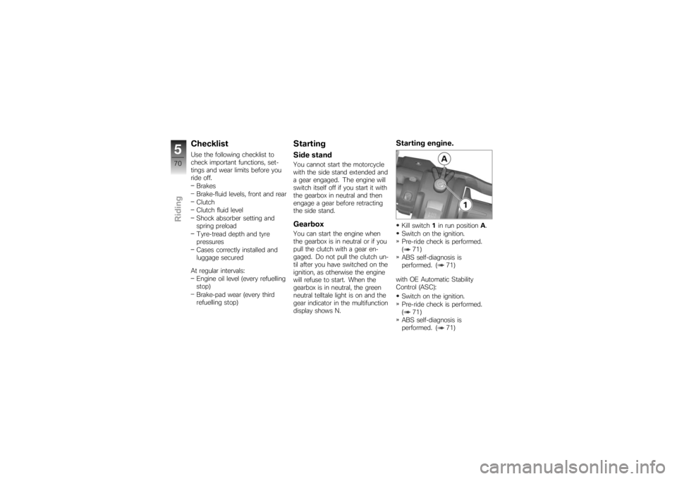
Starting engine.Kill switch 1in run position A.
Switch on the ignition.
Pre-ride check is performed.
( 71)
ABS self-diagnosis is
performed. ( 71)
with OE Automatic Stability
Control (ASC): Switch on the ignition.
Pre-ride check is performed.
( 71)
ABS self-diagnosis is
performed. ( 71)
570zRiding
Page 109 of 166
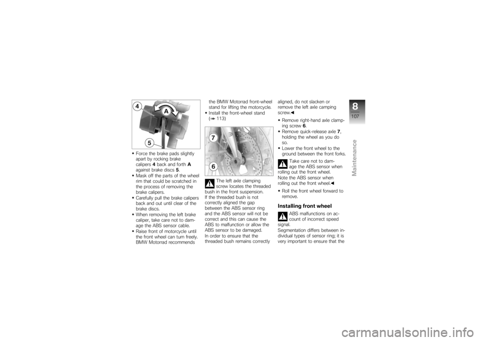
Force the brake pads slightly
apart by rocking brake
calipers4back and forth A
against brake discs 5.
Mask off the parts of the wheel
rim that could be scratched in
the process of removing the
brake calipers.
Carefully pull the brake calipers
back and out until clear of the
brake discs.
When removing the left brake
caliper, take care not to dam-
age the ABS sensor cable.
Raise front of motorcycle until
the front wheel can turn freely.
BMW Motorrad recommends the BMW Motorrad front-wheel
stand for lifting the motorcycle.
Install the front-wheel stand
( 113)
The left axle clamping
screw locates the threaded
bush in the front suspension.
If the threaded bush is not
correctly aligned the gap
between the ABS sensor ring
and the ABS sensor will not be
correct and this can cause the
ABS to malfunction or allow the
ABS sensor to be damaged.
In order to ensure that the
threaded bush remains correctly aligned, do not slacken or
remove the left axle camping
screw.
Remove right-hand axle clamp-
ing screw 6.
Remove quick-release axle 7,
holding the wheel as you do
so.
Lower the front wheel to the
ground between the front forks.
Take care not to dam-
age the ABS sensor when
rolling out the front wheel.
Note the ABS sensor when
rolling out the front wheel.
Roll the front wheel forward to
remove.
Installing front wheel
ABS malfunctions on ac-
count of incorrect speed
signal.
Segmentation differs between in-
dividual types of sensor ring; it is
very important to ensure that the
8107zMaintenance
Page 117 of 166
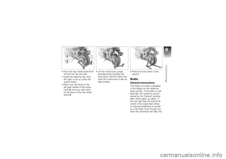
Push the rear wheel stand from
the left into the rear axle.
Install the retaining disc from
the right; to do so, press the
unlock button.
Place your left hand on the
left grab handle of the motor-
cycle4, and your right hand
on the lever of the rear wheel
stand 5. Lift the motorcycle upright,
simultaneously pressing the
lever down until the stand sup-
ports the motorcycle in the up-
right position.
Press the lever down to the
ground.
BulbsGeneral instructionsThe failure of a bulb is signalled
in the display by the defective
lamp symbol. If the brake or rear
light fails, the symbol is accom-
panied by the 'General' warning
light, which lights up yellow. If
the rear light fails the second fil-
ament of the brake light shines
at reduced brightness to double
as a rear light. Even though you
have this substitute rear light, the
8115zMaintenance
Page 122 of 166
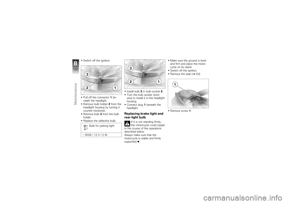
Switch off the ignition.
Pull off the connector1be-
neath the headlight.
Remove bulb holder 2from the
headlight housing by turning it
counter-clockwise.
Remove bulb 3from the bulb
holder.
Replace the defective bulb.
Bulb for parking light
W5W / 12 V / 5 W Install bulb
3in bulb socket 2.
Turn the bulb socket clock-
wise to install it in the headlight
housing.
Connect plug 1beneath the
headlight.
Replacing brake light and
rear light bulb
If it is not standing firmly,
the motorcycle could topple
in the course of the operations
described below.
Always make sure that the
motorcycle is stable and firmly
supported. Make sure the ground is level
and firm and place the motor-
cycle on its stand.
Switch off the ignition.
Remove the seat ( 63)
Remove screw
1.
8120zMaintenance
Page 123 of 166
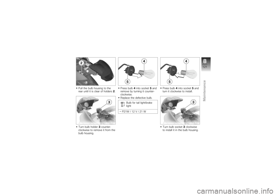
Pull the bulb housing to the
rear until it is clear of holders2.
Turn bulb holder 3counter-
clockwise to remove it from the
bulb housing. Press bulb
4into socket 5and
remove by turning it counter-
clockwise.
Replace the defective bulb.
Bulb for tail light/brake
light
P21W / 12 V / 21 W Press bulb
4into socket 5and
turn it clockwise to install.
Turn bulb socket 3clockwise
to install it in the bulb housing.
8121zMaintenance