2007 BMW M5 SEDAN belt
[x] Cancel search: beltPage 56 of 256

Transporting children safely
54 Before attaching the LATCH child's seat, pull
the belt away from the region of the child
restraint fixing system.
Make sure that the LATCH anchor fittings
are properly engaged and the child
restraint system firmly contacts the backrest.<
Rear seats
The anchor points for the LATCH anchors are
located at the positions indicated by arrows in
the gap between the seat and the backrest.
Rear seats with through-loading
system*
The anchor points for the LATCH anchors are
located behind the indicated protective caps.
Remove the cover caps before mounting the
child's seat.
On trips
If the vehicle is equipped with rear side
airbags, make sure that children do not
lean out of the child's seat towards the door
panels. Otherwise injuries can be caused if the
side airbags are triggered.<
Child-safety locks for rear doors
Slide down the safety lever on the rear doors:
the door can now be opened from the outside
only.
Safety switch for power windows
Always press the safety switch for the power
windows, refer to page38, when children are
riding in the rear of the vehicle.
ba8_m5us.book Seite 54 Montag, 5. Februar 2007 12:03 12
Page 78 of 256

Everything under control
76 6.Select the menu item to be set and press
the controller.
7.Select the desired unit of measure and
press the controller.
The settings are stored for the remote key cur-
rently in use.
Language on Control Display
iDrive, for explanation of principle, refer to
page16.
1.Press the button.
This opens the start menu.
2.Press the controller to open the menu.
3.Select "Settings" and press the controller.
4.Select "Language / Units" and press the
controller.
5.Change to upper field if necessary. Turn the
controller until "Languages" is selected and
press the controller.
6.Select "Text language" and press the con-
troller. You can change the language of the
text displays.
7.Select and activate the desired language by
pressing the controller.
The setting is stored for the remote control cur-
rently in use.
Volume of warning tones*
On vehicles equipped with a single drive, you
can increase or decrease the volume of the
warning tones, e.g. for the safety belt reminder,
compared to the entertainment sound output.
The warning tones have a specified minimum
and maximum volume that cannot be dropped
below or exceeded.1.Select "Tone / volume" and press the con-
troller.
2.Select "Volume settings" and press the
controller.
3.Change to the second field from the top if
necessary. Select "Warning tones" and
press the controller.
4.If necessary, change the field and turn the
controller.
The setting is applied.
ba8_m5us.book Seite 76 Montag, 5. Februar 2007 12:03 12
Page 88 of 256

Technology for comfort, convenience and safety
86
Airbags
The following airbags are located under the
marked covers:
1Front airbags
2Head airbags
3Side airbags in front and rear
Protective action
To ensure that the safety systems con-
tinue to provide optimized protection,
please observe the adjustment instructions on
page41.<
The front airbags help protect the driver and
front passenger by responding to frontal
impacts in which safety belts alone cannot pro-
vide adequate restraint. When needed, the
head and side airbags help provide protection in
the event of side impact. The relevant side air-
bag supports the side upper body area. The
head air bag supports the head.
The airbags are deliberately not triggered in
every impact situation, e. g. less severe acci-
dents or rear-end collisions.
Do not apply adhesive materials to the
cover panels of the airbags, cover them or
modify them in any other way. Do not attempt to
remove the airbag restraint system from the
vehicle. Do not modify or tamper with either the
wiring or the individual components in the air-
bag system. This category includes the uphol-
stery in the center of the steering wheel, on the
instrument panel, the doors and the roof pillars
along with the sides of the headliner. Do not
attempt to remove or dismantle the steering
wheel. Do not touch the individual components
immediately after the system has been trig-gered, because there is a danger of burns.
In the event of malfunctions, deactivation, or
triggering of the airbag restraint system, have
the testing, repair, removal, and disposal of air-
bag generators executed only by a BMW center
or a workshop that works according to BMW
repair procedures with correspondingly trained
personnel and has the required explosives
licenses. Otherwise unprofessional attempts to
service the system could lead to failure in an
emergency or undesired airbag triggering,
either of which could result in personal injury.<
Warnings and information on the airbags is also
provided on the sun visors.
Automatic deactivation of front
passenger airbags
The occupation of the seat is detected by eval-
uating the impression on the occupied seat sur-
face of the front passenger seat. The front and
side airbags on the front passenger side are
activated or deactivated accordingly by the sys-
tem.
The current status of the front passenger
airbag, i.e. deactivated or activated, is
indicated by the indicator lamp over the interior
rearview mirror, refer to Operating state of front
passenger airbags in the following.<
Before transporting a child on the front
passenger seat, observe the safety infor-
mation and handling instructions under Trans-
porting children safely refer to page52.
The front and side airbags on the front passen-
ger side can be deactivated for teenagers and
adults in certain sitting positions; then the indi-
cator lamp for the front passenger airbags lights
ba8_m5us.book Seite 86 Montag, 5. Februar 2007 12:03 12
Page 89 of 256

Controls
87Reference
At a glance
Driving tips
Communications
Navigation
Entertainment
Mobility
up. In these cases, change the sitting position
so that the front passenger airbags are acti-
vated and the indicator lamp goes out. If the
desired status cannot be produced by changing
the sitting position, transport the correspond-
ing person on the rear seat. Do not fit seat cov-
ers, seat cushion padding, ball mats or other
items onto the front passenger seat unless they
are specifically recommended by BMW. Do not
lay objects under the seat which could press
against the seat from below. Otherwise a cor-
rect evaluation of the occupied seat surface
cannot be ensured.<
Operating state of front passenger
airbags
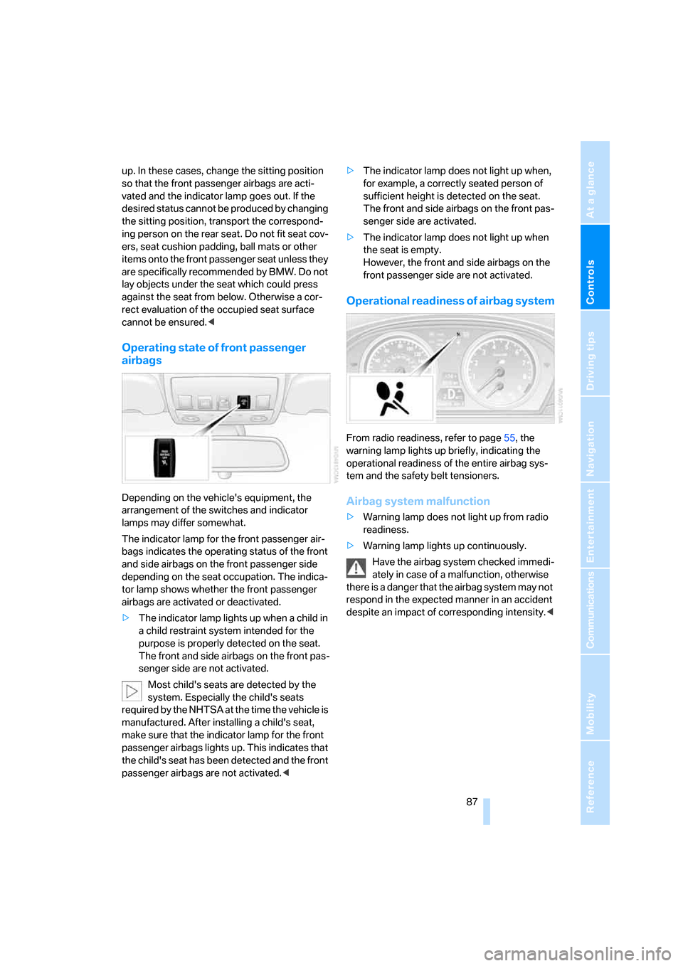
Depending on the vehicle's equipment, the
arrangement of the switches and indicator
lamps may differ somewhat.
The indicator lamp for the front passenger air-
bags indicates the operating status of the front
and side airbags on the front passenger side
depending on the seat occupation. The indica-
tor lamp shows whether the front passenger
airbags are activated or deactivated.
>The indicator lamp lights up when a child in
a child restraint system intended for the
purpose is properly detected on the seat.
The front and side airbags on the front pas-
senger side are not activated.
Most child's seats are detected by the
system. Especially the child's seats
required by the NHTSA at the time the vehicle is
manufactured. After installing a child's seat,
make sure that the indicator lamp for the front
passenger airbags lights up. This indicates that
the child's seat has been detected and the front
passenger airbags are not activated.<>The indicator lamp does not light up when,
for example, a correctly seated person of
sufficient height is detected on the seat.
The front and side airbags on the front pas-
senger side are activated.
>The indicator lamp does not light up when
the seat is empty.
However, the front and side airbags on the
front passenger side are not activated.
Operational readiness of airbag system
From radio readiness, refer to page55, the
warning lamp lights up briefly, indicating the
operational readiness of the entire airbag sys-
tem and the safety belt tensioners.
Airbag system malfunction
>Warning lamp does not light up from radio
readiness.
>Warning lamp lights up continuously.
Have the airbag system checked immedi-
ately in case of a malfunction, otherwise
there is a danger that the airbag system may not
respond in the expected manner in an accident
despite an impact of corresponding intensity.<
ba8_m5us.book Seite 87 Montag, 5. Februar 2007 12:03 12
Page 110 of 256

Practical interior accessories
108
Through-loading system*
Opening
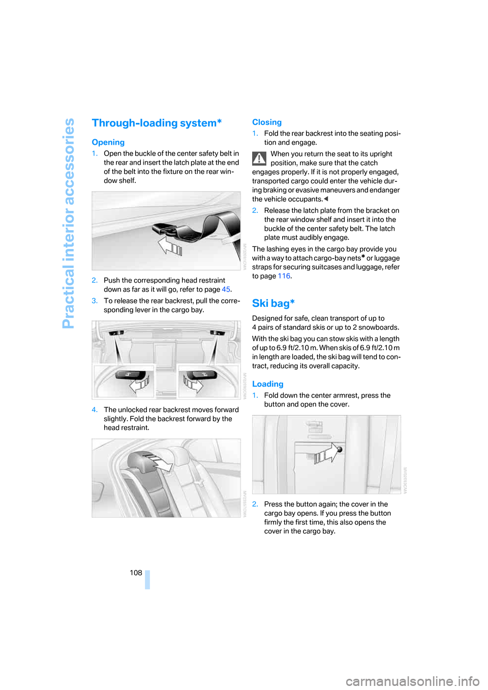
1.Open the buckle of the center safety belt in
the rear and insert the latch plate at the end
of the belt into the fixture on the rear win-
dow shelf.
2.Push the corresponding head restraint
down as far as it will go, refer to page45.
3.To release the rear backrest, pull the corre-
sponding lever in the cargo bay.
4.The unlocked rear backrest moves forward
slightly. Fold the backrest forward by the
head restraint.
Closing
1.Fold the rear backrest into the seating posi-
tion and engage.
When you return the seat to its upright
position, make sure that the catch
engages properly. If it is not properly engaged,
transported cargo could enter the vehicle dur-
ing braking or evasive maneuvers and endanger
the vehicle occupants.<
2.Release the latch plate from the bracket on
the rear window shelf and insert it into the
buckle of the center safety belt. The latch
plate must audibly engage.
The lashing eyes in the cargo bay provide you
with a way to attach cargo-bay nets
* or luggage
straps for securing suitcases and luggage, refer
to page116.
Ski bag*
Designed for safe, clean transport of up to
4 pairs of standard skis or up to 2 snowboards.
With the ski bag you can stow skis with a length
o f u p t o 6 . 9 f t / 2 . 1 0 m . W h e n s k i s o f 6 . 9 f t / 2 . 1 0 m
in length are loaded, the ski bag will tend to con-
tract, reducing its overall capacity.
Loading
1.Fold down the center armrest, press the
button and open the cover.
2.Press the button again; the cover in the
cargo bay opens. If you press the button
firmly the first time, this also opens the
cover in the cargo bay.
ba8_m5us.book Seite 108 Montag, 5. Februar 2007 12:03 12
Page 111 of 256

Controls
109Reference
At a glance
Driving tips
Communications
Navigation
Entertainment
Mobility
3.Extend the ski bag between the front seats
and fill it. The zipper facilitates access to the
stowed items and drying of the ski bag.
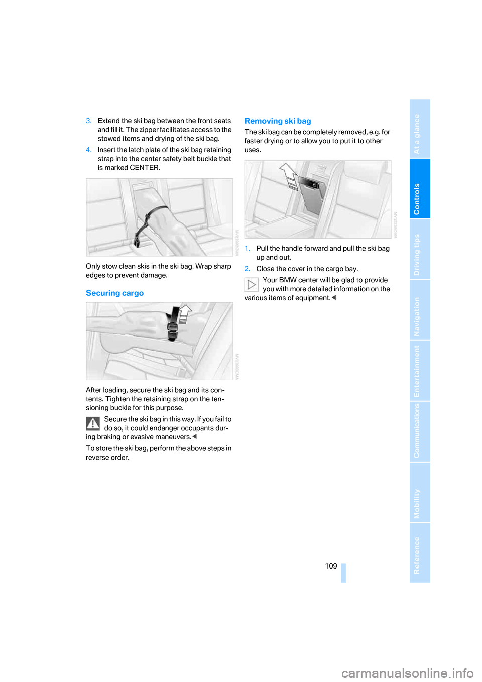
4.Insert the latch plate of the ski bag retaining
strap into the center safety belt buckle that
is marked CENTER.
Only stow clean skis in the ski bag. Wrap sharp
edges to prevent damage.
Securing cargo
After loading, secure the ski bag and its con-
tents. Tighten the retaining strap on the ten-
sioning buckle for this purpose.
Secure the ski bag in this way. If you fail to
do so, it could endanger occupants dur-
ing braking or evasive maneuvers.<
To store the ski bag, perform the above steps in
reverse order.
Removing ski bag
The ski bag can be completely removed, e.g. for
faster drying or to allow you to put it to other
uses.
1.Pull the handle forward and pull the ski bag
up and out.
2.Close the cover in the cargo bay.
Your BMW center will be glad to provide
you with more detailed information on the
various items of equipment.<
ba8_m5us.book Seite 109 Montag, 5. Februar 2007 12:03 12
Page 117 of 256

Driving tips
115Reference
At a glance
Controls
Communications
Navigation
Entertainment
Mobility
Determining loading limit
1.Locate the following statement on your
vehicle's placard
*:
The combined weight of occupants
and cargo should never exceed
XXX lbs. or YYY kg, as otherwise the vehicle
may be damaged and unstable driving con-
ditions may result.<
2.Determine the combined weight of the
driver and passengers that will be riding in
your vehicle.
3.Subtract the combined weight of the driver
and passengers from XXX lbs. or YYY kg.
4.The resulting figure equals the available
amount of cargo and luggage load capacity.
For example, if the XXX amount equals
1,400 lbs. and there will be five 150-lb. pas-
sengers in your vehicle, the amount of avail-
able cargo and luggage load capacity is
650 lbs.:
1,400 lbs. minus 750 lbs. = 650 lbs.
5.Determine the combined weight of luggage
and cargo being loaded on the vehicle. That
weight may not safely exceed the available
cargo and luggage load capacity calculated
in step 4.
6.If your vehicle will be towing a trailer, part of
the load from your trailer will be transferred
to your vehicle. Consult the manual for
transporting a trailer to determine how this
may reduce the available cargo and luggage
load capacity of your vehicle.
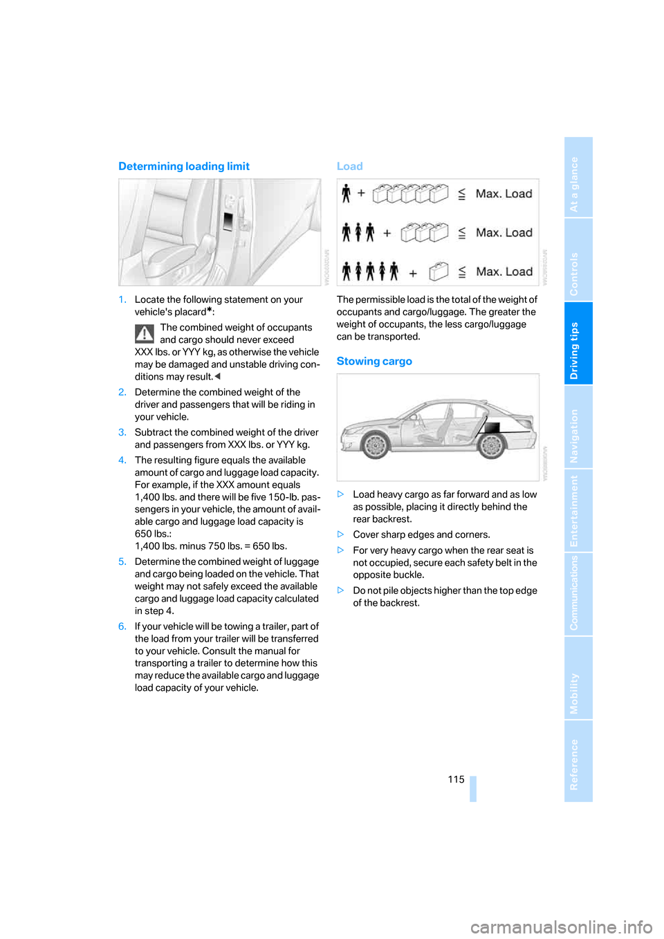
Load
The permissible load is the total of the weight of
occupants and cargo/luggage. The greater the
weight of occupants, the less cargo/luggage
can be transported.
Stowing cargo
>Load heavy cargo as far forward and as low
as possible, placing it directly behind the
rear backrest.
>Cover sharp edges and corners.
>For very heavy cargo when the rear seat is
not occupied, secure each safety belt in the
opposite buckle.
>Do not pile objects higher than the top edge
of the backrest.
ba8_m5us.book Seite 115 Montag, 5. Februar 2007 12:03 12
Page 201 of 256

Mobility
199Reference
At a glance
Controls
Driving tips
Communications
Navigation
Entertainment
Observe all national and local maximum speed
limits, otherwise violations of the law could
occur.
Tire identification marks
Knowledge of the labeling on the side of the tire
makes it easier to identify and choose the right
tires.
Tire size
Speed letter
Q = up to 100 mph/160 km/h
T = up to 118 mph/190 km/h
H = up to 131 mph/210 km/h
V = up to 150 mph/240 km/h
W = up to 167 mph/270 km/h
Y = up to 186 mph/300 km/h
Z = over 150 mph/240 km/h
Tire Identification Number
Tires with DOT codes meet the guidelines of
the U.S. Department of Transportation.
DOT code:
Tire age
The manufacturing date of tires is contained in
the tire coding: DOT... 3406 indicates that the
tire was manufactured in week 34 of 2006.
BMW recommends that you replace all tires
after 6 years at most, even if some tires may last
for 10 years. This also concerns the tire of the
spare wheel.
Uniform Tire Quality Grading
Quality grades can be found where applicable
on the tire sidewall between tread shoulder and
maximum section width. For example:
Tread wear 200 Traction AA
Temperature A
Tire sizePressure specifications in psi/kPa
Traveling speeds
up to max. of
100 mph/160 km/hTraveling speeds
including those exceeding
100 mph/160 km/h
All pressure specifications in
the table are indicated in psi/
kilopascal with cold tires.
Cold = ambient temperature
245/45 R 18 100 V XL M+S 35/240 38/260 35/240 38/260 41/280 46/320
255/40 ZR 19 36/250 - 36/250 - 41/280 -
285/35 ZR 19 - 36/250 - 36/250 - 46/320
More details on the permissible load and weights can be found on page228.
e.g.
Nominal width in mm
Aspect ratio in Ξ
Belted construction – radial
Rim diameter in inches
Carrying capacity ID-code
(not in ZR tires)
Speed code letter
(in ZR tires before the R)
245/45 R18100 V
285/35 ZR19
e.g.
Manufacturer code
for tire make
Tire size and tire design
Tire ageDOT xxxx xxx 3406
ba8_m5us.book Seite 199 Montag, 5. Februar 2007 12:03 12