Page 246 of 508
4 - 24
ENG
3. Install:
�Piston 1
�Piston pin 2
�Piston pin clip 3
NOTE:
�The arrow a on the piston dome must point
to exhaust side.
�Before installing the piston pin clip, cover the
crankcase with a clean rag to prevent the
piston pin clip from falling into the crankcase
cavity.
CAUTION:
Do not allow the clip open ends to meet the
piston pin slot b.
5PA40640
5PA40650
Cylinder head and cylinder
1. Apply:
�Engine oil
To piston 1, piston ring 2 and cylinder
surface.
2. Install:
�Cylinder 1
CAUTION:
Make sure the piston ring is properly posi-
tioned. Install the cylinder with one hand
while compressing the piston ring with the
other hand.
NOTE:
After installing, check the smooth movement of
the piston.
5PA40660
5PA40670
3. Install:
�Nut (cylinder) 1
NOTE:
Tighten the nuts in stage, using a crisscross
pattern.
5PA40680
T R..28 Nm (2.8 m · kg, 20 ft · lb)
CYLINDER HEAD, CYLINDER AND PISTON
Page 306 of 508

4 - 54
ENG
REMOVAL POINTS
Crankcase
1. Remove:
�Right crankcase 1
Use the crankcase separating tool 2.
NOTE:
�Fully tighten the tool holding bolts, but make
sure the tool body is parallel with the case. If
necessary, one screw may be backed out
slightly to level tool body.
�As pressure is applied, alternately tap on the
front engine mounting boss and transmission
shafts.
CAUTION:
�Turn the segment 3 to the position
shown in the figure so that it does not
contact the crankcase.
�Use soft hammer to tap on the case half.
Tap only on reinforced portions of case.
Do not tap on gasket mating surface.
Work slowly and carefully. Make sure the
case halves separate evenly. If one end
“hangs up”, take pressure off the push
screw, realign, and start over. If the cases
do not separate, check for a remaining
case screw or fitting. Do not force.
EC4N3301
Crankshaft
1. Remove:
�Crankshaft 1
Use the crankcase separating tool 2.
NOTE:
Make appropriate bolts 3 as shown available
by yourself and attach the tool with them.
CAUTION:
Do not use a hammer to drive out the
crankshaft.
Crankcase separating tool:
YU-1135-A/90890-01135
Crankcase separating tool:
YU-1135-A/90890-01135
5PA41600
5PA41610
5PA41620
CRANKCASE AND CRANKSHAFT
Page 314 of 508
4 - 58
ENG
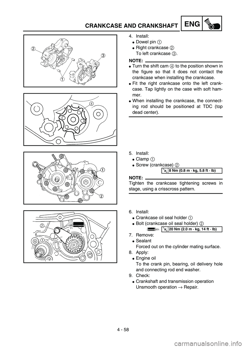
4. Install:
�Dowel pin 1
�Right crankcase 2
To left crankcase 3.
NOTE:
�Turn the shift cam 4 to the position shown in
the figure so that it does not contact the
crankcase when installing the crankcase.
�Fit the right crankcase onto the left crank-
case. Tap lightly on the case with soft ham-
mer.
�When installing the crankcase, the connect-
ing rod should be positioned at TDC (top
dead center).
5PA41760
5PA41770
5. Install:
�Clamp 1
�Screw (crankcase) 2
NOTE:
Tighten the crankcase tightening screws in
stage, using a crisscross pattern.
5PA41780
T R..8 Nm (0.8 m · kg, 5.8 ft · lb)
6. Install:
�Crankcase oil seal holder 1
�Bolt (crankcase oil seal holder) 2
7. Remove:
�Sealant
Forced out on the cylinder mating surface.
8. Apply:
�Engine oil
To the crank pin, bearing, oil delivery hole
and connecting rod end washer.
9. Check:
�Crankshaft and transmission operation
Unsmooth operation → Repair.
5PAR0010
T R..20 Nm (2.0 m · kg, 14 ft · lb)
CRANKCASE AND CRANKSHAFT
Page 454 of 508
6 - 2
–+ELECIGNITION SYSTEM
EC620000
IGNITION SYSTEM
INSPECTION STEPS
Use the following steps for checking the possibility of the malfunctioning engine being attributable to
ignition system failure and for checking the spark plug which will not spark.
*marked: Only when the ignition checker is used.
NOTE:
�Remove the following parts before inspection.
1) Seat
2) Fuel tank
�Use the following special tools in this inspection.
Dynamic spark tester:
YM-34487
Ignition checker:
90890-06754Pocket tester:
YU-3112-C/90890-03112
Spark gap test*Clean or replace
spark plug.
Check entire ignition
system for connection.Repair or replace.
Check engine stop switch. Replace.
Check ignition coil. Primary coil Replace.
Secondary coil Replace.
Check spark plug cap. Replace.
Check CDI magneto. Pickup coil Replace.
Charging coil Replace.
Replace CDI unit.
No spark
OK
OK
OK
OK
OK
Spark
No good
No good
No good
No good
No good
No good
No good
Page 458 of 508
6 - 3
–+ELECIGNITION SYSTEM
SPARK GAP TEST
1. Disconnect the spark plug cap from spark
plug.
2. Connect the dynamic spark tester 1 (igni-
tion checker 2) as shown.
�Spark plug cap 3
�Spark plug 4
ÈFor USA and CDN
ÉExcept for USA and CDN
3. Kick the kickstarter crank.
4. Check the ignition spark gap.
5. Start engine, and increase spark gap until
misfire occurs. (for USA and CDN only)
Minimum spark gap:
6.0 mm (0.24 in)
È
5PA60030
É
5PA60040
EC624000
COUPLERS AND LEADS CONNECTION
INSPECTION
1. Check:
�Couplers and leads connection
Rust/dust/looseness/short-circuit → Repair
or replace.
ENGINE STOP SWITCH INSPECTION
1. Inspect:
�Engine stop switch conduct
No continuous while being pushed → Replace.
Continuous while being freed → Replace. Tester (+) lead
→ Black/White lead
1
Tester (–) lead
→ Black lead
2
B/W
1B
2Tester selec-
tor position
PUSH IN
Ω
× 1
FREE
5PA60050
Page 464 of 508

7 - 1
TUN
EC700000
TUNING
EC710000
ENGINE
Carburetor setting
�The role of fuel is to cool the engine, and in
the case of a 2-stroke engine, to lubricate the
engine in addition to power generation.
Accordingly, if a mixture of air and fuel is too
lean, abnormal combustion will occur, and
engine seizure may result. If the mixture is
too rich, spark plugs will get wet with oil, thus
making it impossible to bring the engine into
full play or if the worst comes to the worst,
the engine may stall.
�The richness of the air-fuel mixture required
for the engine will vary with atmospheric con-
ditions of the day and therefore, the settings
of the carburetor must be properly suited to
the atmospheric conditions (air pressure,
humidity and temperature).
�Finally, the rider himself must make a test
run and check his machine for conditions
(pick-up of engine speed, road surface con-
ditions) and for the discoloration of the spark
plug(s).
After taking these into consideration, he must
select the best possible carburetor settings.
* It is advisable to make a note of settings,
atmospheric conditions, road surface condi-
tion, lap-time, etc. so that the memorandum
can be used as a reference useful for future.
Atmospheric conditions and carburetor
settings
The air density (i.e., concentration of oxygen
in the air) determines the richness or lean-
ness of the air/fuel mixture. Therefore, refer
to the above table for mixture settings.
Air temp. HumidityAir
pressure
(altitude)Mixture Setting
High High Low (high) Richer Leaner
Low Low High (low) Leaner Richer
SETTING
Page 466 of 508
7 - 2
TUN
That is:
�Higher temperature expands the air with its
resultant reduced density.
�Higher humidity reduces the amount of oxy-
gen in the air by so much of the water vapor
in the same air.
�Lower atmospheric pressure (at a high alti-
tude) reduces the density of the air.
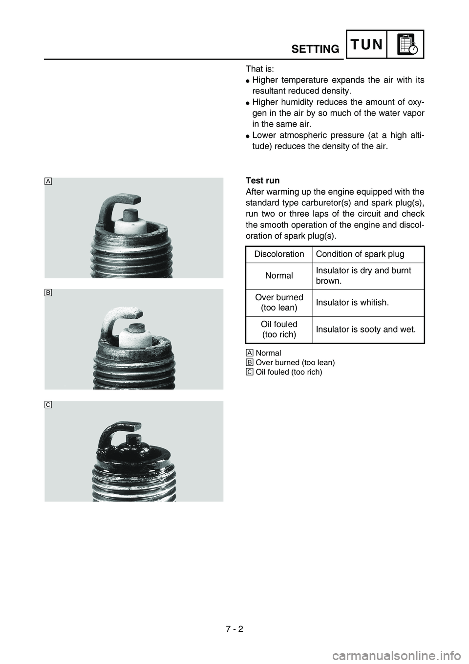
Test run
After warming up the engine equipped with the
standard type carburetor(s) and spark plug(s),
run two or three laps of the circuit and check
the smooth operation of the engine and discol-
oration of spark plug(s).
ÈNormal
ÉOver burned (too lean)
ÊOil fouled (too rich)
Discoloration Condition of spark plug
NormalInsulator is dry and burnt
brown.
Over burned
(too lean)Insulator is whitish.
Oil fouled
(too rich)Insulator is sooty and wet.
5PA70010
È
É
Ê
SETTING
Page 476 of 508

7 - 7
TUN
Road condition and examples of carburetor setting
NOTE:
Optimum pilot air screw setting can be obtained by adding the ex-factory number of the same screw
back-out turns to any required value provided in the chart.
For example, if the ex-factory number is “2”, add “2” to the value chosen in the chart.
Examples of carburetor setting depending on symptomConditions
PartsGeneral condition Sandy condition
Under 10 °C
(50 °F)
(Winter)15 ~ 25 °C
(59 ~ 77 °F)
(Spring, Autumn)
Over 30 °C
(86 °F)
(Summer)Under 10 °C
(50 °F)
(Winter)15 ~ 25 °C
(59 ~ 77 °F)
(Spring, Autumn)
Over 30 °C
(86 °F)
(Summer)
Main jet #140 #138 #135 ~ #138 #142 #142 #142
Jet needle NBKF-2 NBKF-2 NBKF-2 NBKF-2 NBKF-2 NBKF-2
Pilot jet #45 #45 #45 #48 #48 #48
Pilot air screw Zero Zero +1/4–1/2–1/2 Zero ~ +1/2
Symptom Setting Checking
At full throttle
Stall at high speeds
*Hard breathing
Shearing noise
Whitish spark plug
Lean mixtureIncrease main jet calibration no.
(Gradually)Discoloration of spark plug →
If tan color, it is in good condition.
If cannot be corrected:
Clogged float valve seat
Clogged fuel hose
Clogged fuel cock
At full throttle
Speed pick-up stops
Slow speed pick-up
Slow response
Sooty spark plug
Rich mixtureDecrease main jet calibration no.
(Gradually)
*In case of racing slight enrich-
ment of mixture reduces engine
trouble.Discoloration of spark plug →
If tan color, it is in good condition.
If cannot be corrected:
Clogged air filter
Fuel overflow from carburetor
Lean mixture Use jet needle with a smaller
diameter, or NBLF.
Lower jet needle clip position.
The clip position is the jet needle
groove on which the clip is
installed. The positions are num-
bered from the top. Rich mixture Use jet needle with a larger diam-
eter, or NBKG.
Raise jet needle clip position.
1/4 ~ 3/4 throttle
*Hard breathing
Lack of speedUse jet needle with a smaller
diameter, or NBLF.
Lower jet needle clip position.
1/4 ~ 1/2 throttle
Slow speed pick-up
White smoke
Poor accelerationUse jet needle with a larger diam-
eter, or NBKG.
Raise jet needle clip position.
Closed to 1/4 throttle
*Hard breathing
Speed downUse jet needle with a smaller
diameter.
Turn out pilot air screw.
Leaner
↑(Standard)
↓
Richer
SETTING