Page 738 of 786

7 - 1
TUN
EC700000
TUNING
EC710000
ENGINE
Carburetor setting
•The air/fuel mixture will vary depending on
atmospheric conditions. Therefore, it is nec-
essary to take into consideration the air pres-
sure, ambient temperature, humidity, etc.,
when adjusting the carburetor.
•Perform a test run to check for proper engine
performance (e.g., throttle response) and
spark plug(-s) discoloration or fouling. Use
these readings to determine the best possi-
ble carburetor setting.
NOTE:
It is recommended to keep a record of all car-
buretor settings and external conditions (e.g.,
atmospheric conditions, track/surface condi-
tions, lap times) to make future carburetor set-
ting easier.
WARNING
The carburetor is a part of the fuel line.
Therefore, be sure to install it in a well-
ventilated area, away from flammable
objects and any sources of fire.
Never look into the carburetor intake.
Flames may shoot out from the pipe if the
engine backfires while it is being started.
Gasoline may be discharged from the
accelerator pump nozzle when the carbu-
retor has been removed.
SETTING
Page 740 of 786

7 - 2
TUN
CAUTION:
The carburetor is extremely sensitive to
foreign matter (dirt, sand, water, etc.).
During installation, do not allow foreign
matter to get into the carburetor.
Always handle the carburetor and its
components carefully. Even slight
scratches, bends or damage to carburetor
parts may prevent the carburetor from
functioning correctly. Carefully perform
all servicing with the appropriate tools
and without applying excessive force.
When the engine is stopped or when
riding at no load, do not open and close
the throttle unnecessarily. Otherwise, too
much fuel may be discharged, starting
may become difficult or the engine may
not run well.
After installing the carburetor, check that
the throttle operates correctly and opens
and closes smoothly.
Atmospheric conditions and carburetor
settings
The air density (i.e., concentration of oxygen
in the air) determines the richness or lean-
ness of the air/fuel mixture. Therefore, refer
to the above table for mixture settings.
That is:
•Higher temperature expands the air with its
resultant reduced density.
•Higher humidity reduces the amount of oxy-
gen in the air by so much of the water vapor
in the same air.
•Lower atmospheric pressure (at a high alti-
tude) reduces the density of the air.
Air temp. HumidityAir
pressure
(altitude)Mixture Setting
High High Low (high) Richer Leaner
Low Low High (low) Leaner Richer
SETTING
Page 744 of 786
7 - 4
TUNSETTING
Main jet adjustment
The richness of the air-fuel mixture at full throt-
tle can be set by changing the main jet 1.
If the air-fuel mixture is too rich or too lean, the
engine power will drop, resulting in poor accel-
eration.
Effects of changing the main jet (reference)
ÈIdle
ÉFully open
Standard main jet #165
1/4 1/2 3/4
+10%
#165
–10%
#175
#155
ÈÉ
Pilot jet adjustment
The richness of the air-fuel mixture with the
throttle open 1/4 or less can be set by adjust-
ing the pilot jet 1.
Standard pilot jet #45
Effects of adjusting the pilot jet (reference)
ÈIdle
ÉFully open
1/4 1/2 3/4
+5%
–5%
#48
#42#45
È
É
Page 746 of 786

7 - 5
TUNSETTING
Jet needle groove position adjustment
NOTE:
For setting adjustment, replace the standard
jet needle with the one designed for setting.
Adjusting the jet needle 1 position affects the
acceleration when the throttle is 1/8 to 3/4
open.
1. Too rich at intermediate speeds
Rough engine operation is felt and the
engine will not pick up speed smoothly. In
this case, step up the jet needle clip by one
groove and move down the needle to lean
out the mixture.
2. Too lean at intermediate speeds
The engine breathes hard and will not pick
up speed quickly.
Step down the jet needle clip by one
groove and move up the needle to enrich
the mixture.
Effects of changing the jet needle groove
position (reference)
ÈIdle
ÉFully open
1No.5 groove
2No.3 groove
3No.4 groove
Jet needle adjustment
The jet needle is adjusted by changing it.
The tapered sections of all jet needles have
the same starting positions, but the needles
are available with different straight-portion
diameters.
OBDUS - 4
Clip position
Diameter
a of straight portion Supplied jet needle OBDUS
1/4 1/2 3/4
+10%
–10%
1
23
É È
Page 748 of 786

7 - 6
TUN
Effects of changing the jet needle (refer-
ence)
(Diameter of the straight portion)
Changing the diameter of the straight portion
adjusts the air-fuel mixture when the throttle is
1/8 to 1/4 open.
ÈIdle
ÉFully open
1/4 1/2 3/4
+10%
S
–10%
R
T
ÈÉ
Leak jet adjustment (accelerator pump
adjustment)
The leak jet 1 is a setting part that adjusts the
flow of fuel discharged by the accelerator
pump. Since the accelerator pump operates
only when throttle is open, the leak jet is used
to adjust a fuel mixture ratio for quick throttle
opening and is therefore different from other
setting parts that adjust a fuel mixture for each
throttle opening (each engine speed).
1. The engine breathes hard in quick throttle
opening.
Select a leak jet having lower calibrating
No. than standard to enrich the mixture.
#50 → #45
2. Rough engine operation is felt in quick
throttle opening.
Select a leak jet having higher calibrating
No. than standard to lean out the mixture.
#50 → #55
Standard leak jet #501
SETTING
Page 752 of 786

7 - 8
TUN
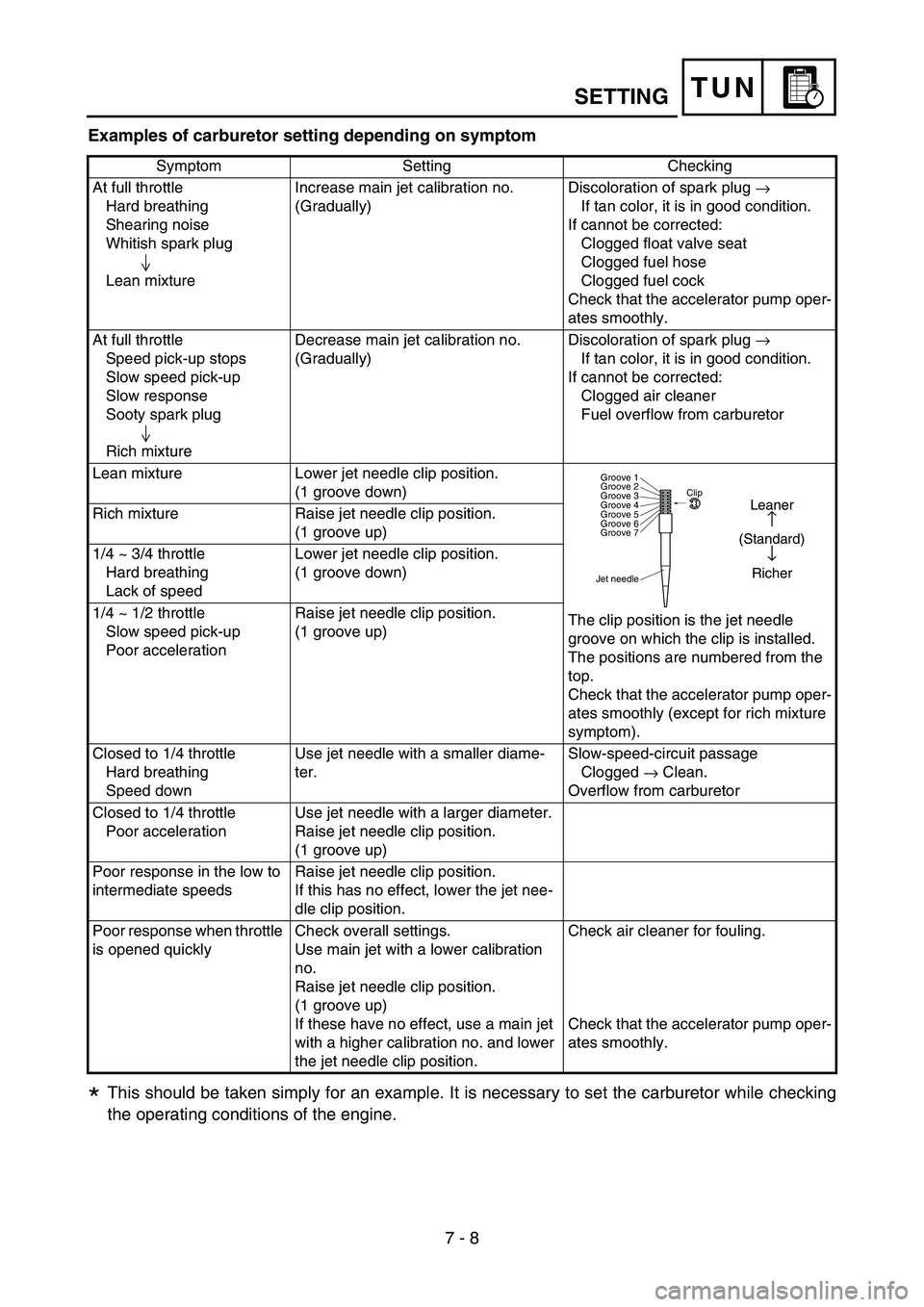
Examples of carburetor setting depending on symptom
This should be taken simply for an example. It is necessary to set the carburetor while checking
the operating conditions of the engine.
Symptom Setting Checking
At full throttle
Hard breathing
Shearing noise
Whitish spark plug
Lean mixtureIncrease main jet calibration no.
(Gradually)Discoloration of spark plug
→
If tan color, it is in good condition.
If cannot be corrected:
Clogged float valve seat
Clogged fuel hose
Clogged fuel cock
Check that the accelerator pump oper-
ates smoothly.
At full throttle
Speed pick-up stops
Slow speed pick-up
Slow response
Sooty spark plug
Rich mixtureDecrease main jet calibration no.
(Gradually)Discoloration of spark plug
→
If tan color, it is in good condition.
If cannot be corrected:
Clogged air cleaner
Fuel overflow from carburetor
Lean mixture Lower jet needle clip position.
(1 groove down)
The clip position is the jet needle
groove on which the clip is installed.
The positions are numbered from the
top.
Check that the accelerator pump oper-
ates smoothly (except for rich mixture
symptom). Rich mixture Raise jet needle clip position.
(1 groove up)
1/4 ~ 3/4 throttle
Hard breathing
Lack of speedLower jet needle clip position.
(1 groove down)
1/4 ~ 1/2 throttle
Slow speed pick-up
Poor accelerationRaise jet needle clip position.
(1 groove up)
Closed to 1/4 throttle
Hard breathing
Speed downUse jet needle with a smaller diame-
ter.Slow-speed-circuit passage
Clogged
→ Clean.
Overflow from carburetor
Closed to 1/4 throttle
Poor accelerationUse jet needle with a larger diameter.
Raise jet needle clip position.
(1 groove up)
Poor response in the low to
intermediate speedsRaise jet needle clip position.
If this has no effect, lower the jet nee-
dle clip position.
Poor response when throttle
is opened quicklyCheck overall settings.
Use main jet with a lower calibration
no.
Raise jet needle clip position.
(1 groove up)
If these have no effect, use a main jet
with a higher calibration no. and lower
the jet needle clip position.Check air cleaner for fouling.
Check that the accelerator pump oper-
ates smoothly.
Jet needleClip
Groove 7 Groove 6
Groove 5
Groove 4
Groove 3
Groove 2
Groove 1
Leaner
↑
(Standard)
↓
Richer
*
SETTING
Page 756 of 786

7 - 9
TUN
EC720000
CHASSIS
EC71P002
Selection of the secondary reduction ratio
(Sprocket)
reduction ratio>
•It is generally said that the secondary gear
ratio should be reduced for a longer straight
portion of a speed course and should be
increased for a course with many corners.
Actually, however, as the speed depends on
the ground condition of the day of the race,
be sure to run through the circuit to set the
machine suitable for the entire course.
•In actuality, it is very difficult to achieve set-
tings suitable for the entire course and some
settings may be sacrificed. Thus, the settings
should be matched to the portion of the
course that has the greatest effect on the
race result. In such a case, run through the
entire course while making notes of lap times
to find the best balance; then, determine the
secondary reduction ratio.
•If a course has a long straight portion where
a machine can run at maximum speed, the
machine is generally set such that it can
develop its maximum revolutions toward the
end of the straight line, with care taken to
avoid the engine over-revving.
NOTE:
Riding technique varies from rider to rider and
the performance of a machine also vary from
machine to machine. Therefore, do not imitate
other rider’s settings from the beginning but
choose your own setting according to the level
of your riding technique.
Secondary
reduction
ratio
=Number of driven sprocket teeth
Number of drive sprocket teeth
Standard secondary
reduction ratio50/14 (3.571)
SETTING
Page 768 of 786

7 - 15
TUN
EC72B000
Rear suspension setting
The rear suspension setting should be made
depending on the rider’s feeling of an actual
run and the circuit conditions.
The rear suspension setting includes the fol-
lowing two factors:
1. Setting of spring preload
•Change the set length of the spring.
•Change the spring.
2. Setting of damping force
•Change the rebound damping.
•Change the compression damping.
EC72C001
Choosing set length
1. Place a stand or block under the engine to
put the rear wheel above the floor, and
measure the length a between the rear
wheel axle center and the rear fender hold-
ing bolt.
2. Remove the stand or block from the engine
and with a rider astride the seat, measure
the sunken length b between the rear
wheel axle center and the rear fender hold-
ing bolt.
3. Loosen the locknut 1 and make adjust-
ment by turning the spring adjuster 2 to
achieve the standard figure from the sub-
traction of the length b from the length a.
Standard figure:
90 ~ 100 mm (3.5 ~ 3.9 in)
SETTING