Page 224 of 390
4 - 15
ENGCAMSHAFT AND ROCKER ARMS
3. Apply:
Molybdenum disulfide oil
(onto the rocker arm and rocker arm
shaft)
4. Install:
Rocker arm 1
Rocker arm shaft 2
Page 232 of 390
4 - 19
ENGVALVES AND VALVE SPRINGS
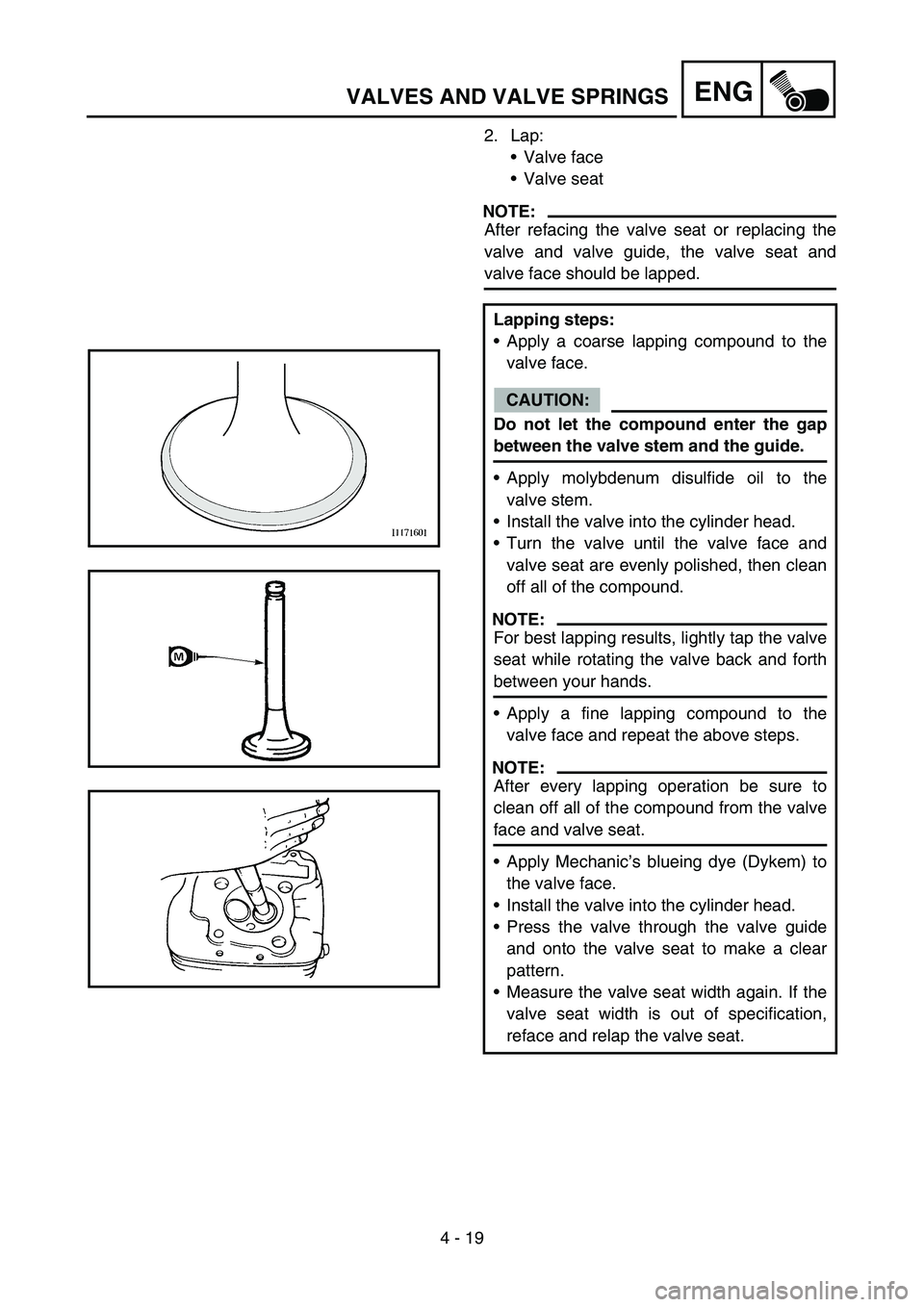
2. Lap:
Valve face
Valve seat
NOTE:
After refacing the valve seat or replacing the
valve and valve guide, the valve seat and
valve face should be lapped.
Lapping steps:
Apply a coarse lapping compound to the
valve face.
CAUTION:
Do not let the compound enter the gap
between the valve stem and the guide.
Apply molybdenum disulfide oil to the
valve stem.
Install the valve into the cylinder head.
Turn the valve until the valve face and
valve seat are evenly polished, then clean
off all of the compound.
NOTE:
For best lapping results, lightly tap the valve
seat while rotating the valve back and forth
between your hands.
Apply a fine lapping compound to the
valve face and repeat the above steps.
NOTE:
After every lapping operation be sure to
clean off all of the compound from the valve
face and valve seat.
Apply Mechanic’s blueing dye (Dykem) to
the valve face.
Install the valve into the cylinder head.
Press the valve through the valve guide
and onto the valve seat to make a clear
pattern.
Measure the valve seat width again. If the
valve seat width is out of specification,
reface and relap the valve seat.
Page 234 of 390
4 - 20
ENGVALVES AND VALVE SPRINGS
ASSEMBLY AND INSTALLATION
1. Apply:
Molybdenum disulfide oil
(onto the valve stem and valve stem seal)
2. Install:
Valve stem seats
Valves
Valve springs
Valve spring retainers
NOTE:
Make sure that each valve is installed in its
original place, also referring to the embossed
mark as follows.
Intake: “G”
Exhaust: “L”
Install the valve springs with the larger pitch
a facing upwards.
bSmaller pitch
New
3. Install:
Valve cotters
NOTE:
While compressing the valve spring with a
valve spring compressor and attachment 1
install the valve cotters.
Valve spring compressor:
YM-4019/90890-04019
4. To secure the valve cotters onto the valve
stem, lightly tap the valve tip with a piece of
wood.
CAUTION:
Hitting the valve tip with excessive force
could damage the valve.
Page 242 of 390
4 - 24
ENGCYLINDER AND PISTON
Piston ring
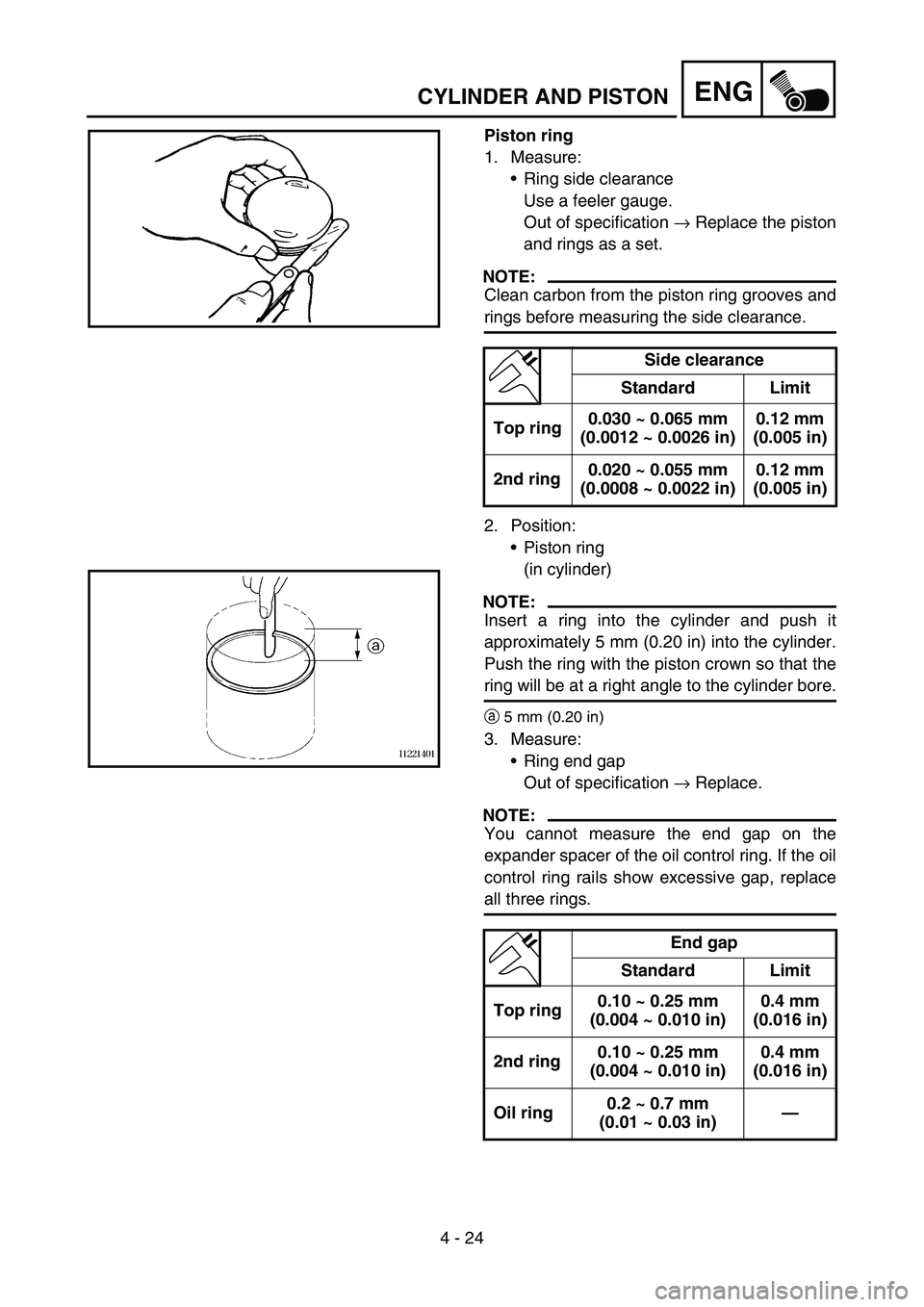
1. Measure:
Ring side clearance
Use a feeler gauge.
Out of specification → Replace the piston
and rings as a set.
NOTE:
Clean carbon from the piston ring grooves and
rings before measuring the side clearance.
2. Position:
Piston ring
(in cylinder)
NOTE:
Insert a ring into the cylinder and push it
approximately 5 mm (0.20 in) into the cylinder.
Push the ring with the piston crown so that the
ring will be at a right angle to the cylinder bore.
a5 mm (0.20 in)
3. Measure:
Ring end gap
Out of specification → Replace.
NOTE:
You cannot measure the end gap on the
expander spacer of the oil control ring. If the oil
control ring rails show excessive gap, replace
all three rings.
Side clearance
Standard Limit
Top ring0.030 ~ 0.065 mm
(0.0012 ~ 0.0026 in)0.12 mm
(0.005 in)
2nd ring0.020 ~ 0.055 mm
(0.0008 ~ 0.0022 in)0.12 mm
(0.005 in)
End gap
Standard Limit
Top ring0.10 ~ 0.25 mm
(0.004 ~ 0.010 in)0.4 mm
(0.016 in)
2nd ring0.10 ~ 0.25 mm
(0.004 ~ 0.010 in)0.4 mm
(0.016 in)
Oil ring0.2 ~ 0.7 mm
(0.01 ~ 0.03 in)—
Page 244 of 390
4 - 25
ENGCYLINDER AND PISTON
Piston pin
1. Inspect:
Piston pin
Blue discoloration/grooves →
Replace, then inspect the lubrication sys-
tem.
2. Measure:
Piston pin outside diameter
Piston pin bore inside diameter
ASSEMBLY AND INSTALLATION
Piston
1. Install:
Piston rings
(onto the piston)
NOTE:
Be sure to install the piston rings so that the
manufacturer’s marks or numbers are
located on the upper side of the rings.
Lubricate the piston and piston rings liberally
with engine oil. Measurement steps:
Measure the piston pin outside diameter
a.
If out of specification, replace the piston
pin.
Outside diameter (piston pin):
12.996 ~ 13.000 mm
(0.5117 ~ 0.5118 in)
:12.976 mm (0.5109 in)
Measure the piston inside diameter b.
If out of specification, replace the piston.
Inside diameter (piston):
13.002 ~ 13.013 mm
(0.5119 ~ 0.5123 in)
: 13.045 mm (0.5136 in)
Page 246 of 390
4 - 26
ENGCYLINDER AND PISTON
2. Position:
Top ring
2nd ring
Oil ring
Offset the piston ring end gaps as shown.
aTop ring end
bOil ring end (lower)
cOil ring end (upper)
d2nd ring end
3. Install:
Piston 1
Piston pin 2
Piston pin clips 3
NOTE:
Apply engine oil onto the piston pin, piston
ring and piston.
Be sure that the arrow mark
a on the piston
points to the exhaust side of the engine.
Before installing the piston pin clip, cover the
crankcase with a clean rag to prevent the
piston pin clip from falling into the crankcase.
4. Lubricate:
Piston
Piston rings
Cylinder
NOTE:
Apply a liberal coating of engine oil.
New
Cylinder
1. Install:
Dowel pins
Gasket
Cylinder 1
NOTE:
Install the cylinder with one hand while com-
pressing the piston rings with the other hand.
CAUTION:
Be careful not to damage the timing chain
damper during installation.
Pass the timing chain through the timing
chain cavity.
New
Page 248 of 390
4 - 27
ENGCLUTCH
CLUTCH
CRANKCASE COVER (LEFT AND RIGHT)
Extent of removal:
1 Crankcase cover (left) removal
2 Crankcase cover (right) removal
Extent of removal Order Part name Q’ty Remarks
CRANKCASE COVER (LEFT
AND RIGHT) REMOVAL
Preparation for removal Drain the engine oil. Refer to “ENGINE OIL REPLACEMENT”
section in the CHAPTER 3.
1 Shift pedal 1
2 Drive sprocket cover 1
3 Crankcase cover (left) 1
4 Gasket 1
5 Dowel pin 2
6 Clutch adjusting screw 1
7 Kick crank 1
8 Crankcase cover (right) 1
9 Gasket 1
10 Dowel pin 2
2
1
Page 266 of 390
4 - 36
ENGOIL PUMP
OIL PUMP
Extent of removal:
1 Oil pump removal
2 Oil strainer removal
3 Oil pump disassembly
Extent of removal Order Part name Q’ty Remarks
OIL PUMP REMOVAL AND DIS-
ASSEMBLY
Preparation for removal Clutch housing and clutch carrier Refer to “CLUTCH” section.
Shift shaft Refer to “SHIFT SHAFT” section.
1 Rotary filter 1
2 Oil pump assembly 1
3 Gasket 1
4 Oil pump drive gear 1
5 Oil strainer 1
6 Circlip 1
7 Oil pump driven gear 1
8 Spring washer 1
9 Circlip 1
10 Washer 1
2
1
3