Page 69 of 390

SPEC
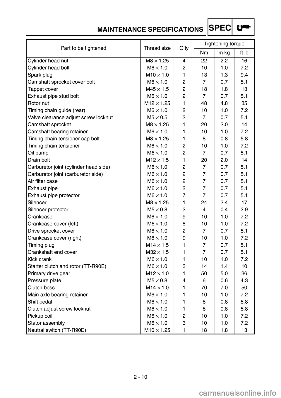
2 - 10 Part to be tightened Thread size Q’tyTightening torque
Nm m·kg ft·lb
Cylinder head nut M8 × 1.25 4 22 2.2 16
Cylinder head bolt M6 × 1.0 2 10 1.0 7.2
Spark plug M10 × 1.0 1 13 1.3 9.4
Camshaft sprocket cover bolt M6 × 1.0 2 7 0.7 5.1
Tappet cover M45 × 1.5 2 18 1.8 13
Exhaust pipe stud bolt M6 × 1.0 2 7 0.7 5.1
Rotor nut M12 × 1.25 1 48 4.8 35
Timing chain guide (rear) M6 × 1.0 2 10 1.0 7.2
Valve clearance adjust screw locknut M5 × 0.5 2 7 0.7 5.1
Camshaft sprocket M8 × 1.25 1 20 2.0 14
Camshaft bearing retainer M6 × 1.0 1 10 1.0 7.2
Timing chain tensioner cap bolt M8 × 1.25 1 8 0.8 5.8
Timing chain tensioner M6 × 1.0 2 10 1.0 7.2
Oil pump M6 × 1.0 2 7 0.7 5.1
Drain bolt M12 ×
1.5 1 20 2.0 14
Carburetor joint (cylinder head side) M6 ×
1.0 2 7 0.7 5.1
Carburetor joint (carburetor side) M6 ×
1.0 2 7 0.7 5.1
Air filter case M6 ×
1.0 2 7 0.7 5.1
Exhaust pipe M6 ×
1.0 2 7 0.7 5.1
Exhaust pipe protector M6 ×
1.0 7 7 0.7 5.1
Silencer M8 ×
1.25 1 24 2.4 17
Silencer protector M5 ×
0.8 2 4 0.4 2.9
Crankcase M6 × 1.0 9 10 1.0 7.2
Crankcase cover (left) M6 ×
1.0 8 10 1.0 7.2
Drive sprocket cover M6 × 1.0 2 7 0.7 5.1
Crankcase cover (right) M6 × 1.0 9 10 1.0 7.2
Timing plug M14 ×
1.5 1 7 0.7 5.1
Crankshaft end cover M32 ×
1.5 1 7 0.7 5.1
Kick crank M6 ×
1.0 1 10 1.0 7.2
Starter clutch and rotor (TT-R90E) M6 ×
1.0 3 14 1.4 10
Primary drive gear M12 ×
1.0 1 50 5.0 36
Pressure plate M5 ×
0.8 4 6 0.6 4.3
Clutch boss M14 ×
1.0 1 70 7.0 50
Main axle bearing retainer M6 × 1.0 1 10 1.0 7.2
Shift pedal M6 × 1.0 1 8 0.8 5.8
Clutch adjust screw locknut M6 × 1.0 1 8 0.8 5.8
Pickup coil M6 × 1.0 2 10 1.0 7.2
Stator assembly M6 × 1.0 3 10 1.0 7.2
Neutral switch (TT-R90E) M10 × 1.25 1 18 1.8 13
MAINTENANCE SPECIFICATIONS
Page 144 of 390

3 - 7
INSP
ADJ
ENGINE OIL REPLACEMENT
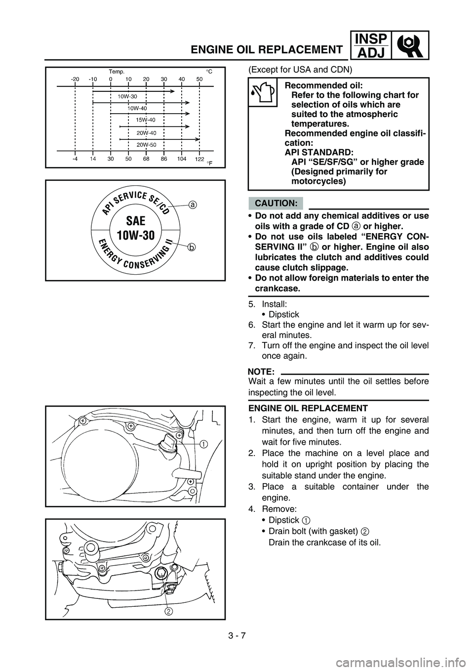
(Except for USA and CDN)
CAUTION:
Do not add any chemical additives or use
oils with a grade of CD
a or higher.
Do not use oils labeled “ENERGY CON-
SERVING II”
b or higher. Engine oil also
lubricates the clutch and additives could
cause clutch slippage.
Do not allow foreign materials to enter the
crankcase.
5. Install:
Dipstick
6. Start the engine and let it warm up for sev-
eral minutes.
7. Turn off the engine and inspect the oil level
once again.
NOTE:
Wait a few minutes until the oil settles before
inspecting the oil level.
Recommended oil:
Refer to the following chart for
selection of oils which are
suited to the atmospheric
temperatures.
Recommended engine oil classifi-
cation:
API STANDARD:
API “SE/SF/SG” or higher grade
(Designed primarily for
motorcycles)
a
b
ENGINE OIL REPLACEMENT
1. Start the engine, warm it up for several
minutes, and then turn off the engine and
wait for five minutes.
2. Place the machine on a level place and
hold it on upright position by placing the
suitable stand under the engine.
3. Place a suitable container under the
engine.
4. Remove:
Dipstick 1
Drain bolt (with gasket) 2
Drain the crankcase of its oil.
Page 146 of 390
3 - 8
INSP
ADJ
PILOT AIR SCREW ADJUSTMENT
5. Install:
Gasket
Drain bolt
New
T R..20 Nm (2.0 m · kg, 14 ft · lb)
6. Fill:
Crankcase
Oil quantity:
Periodic oil change:
0.8 L (0.70 Imp qt, 0.85 US qt)
7. Install:
Dipstick
8. Inspect:
Engine (for oil leaks)
Oil level
Refer to “ENGINE OIL LEVEL INSPEC-
TION”.
PILOT AIR SCREW ADJUSTMENT
1. Adjust:
Pilot air screw 1
Adjusting steps:
Screw in the pilot air screw until it is lightly
seated.
Back out by the specified number of turns.
Pilot air screw:
1-3/4 turns out
Page 316 of 390
5 - 11
CHASFRONT FORK
EC558000
FRONT FORK DISASSEMBLY
Extent of removal:
1 Oil seal removal
2 Damper rod removal
Extent of removal Order Part name Q’ty Remarks
FRONT FORK DISASSEMBLY
Preparation for disas-
semblyDrain the fork oil.
1 Adjuster 1
2 Fork spring 1
3 Dust cover 1
4 Stopper ring 1
5 Bolt (damper rod) 1 Use special tool.
Refer to “REMOVAL POINTS”.
6 Inner tube 1
7 Damper rod 1
8 Oil seal 1
9 Outer tube 1
2
1