Page 338 of 610
4 - 40
ENGCLUTCH AND PRIMARY DRIVEN GEAR
EC490000
CLUTCH AND PRIMARY DRIVEN GEAR
EC498000
CLUTCH PLATE AND FRICTION PLATE
Extent of removal:1 Clutch plate and friction plate removal
Extent of removal Order Part name Q’ty Remarks
CLUCTH PLATE AND FRIC-
TION PLATE REMOVAL
Preparation for removal Drain the engine oil. Refer to “ENGINE OIL REPLACEMENT”
section in the CHAPTER 3.
Engine skidplate Refer to “ENGINE REMOVAL” section.
Starter motor for the TT-R125E/
TT-R125LWE1 Refer to “ELECTRIC STARTING SYS-
TEM” section in the CHAPTER 6 for the
TT-R125E/TT-R125LWE.
1 Kickstarter crank 1
2 Starter motor lead holder 2 TT-R125E/TT-R125LWE
3 Negative battery lead 1 TT-R125E/TT-R125LWE
4 Gasket 1
5 Dowel pin 2
6 Pressure plate 1
7 Ball 1
8 Friction plate 5
9 Clutch plate 4
10 Nut/washer 1/1
11 Push rod 1 1
12Push plate
1
1
Page 352 of 610
4 - 47
ENGCLUTCH AND PRIMARY DRIVEN GEAR
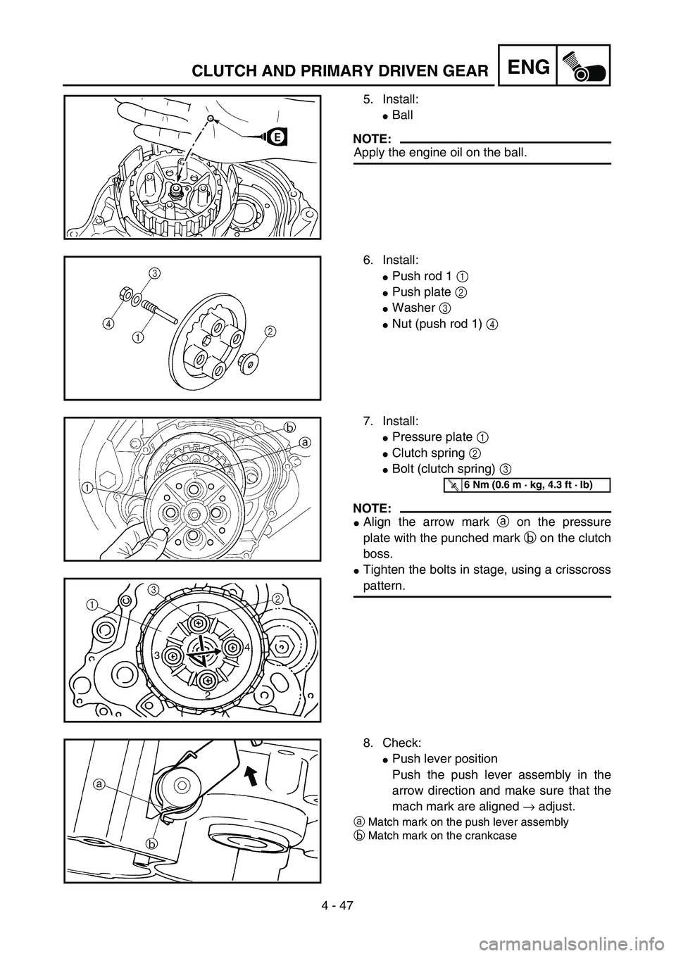
5. Install:
�Ball
NOTE:
Apply the engine oil on the ball.
6. Install:
�Push rod 1 1
�Push plate 2
�Washer 3
�Nut (push rod 1) 4
7. Install:
�Pressure plate 1
�Clutch spring 2
�Bolt (clutch spring) 3
NOTE:
�Align the arrow mark a on the pressure
plate with the punched mark b on the clutch
boss.
�Tighten the bolts in stage, using a crisscross
pattern.
T R..6 Nm (0.6 m · kg, 4.3 ft · lb)
8. Check:
�Push lever position
Push the push lever assembly in the
arrow direction and make sure that the
mach mark are aligned → adjust.
aMatch mark on the push lever assembly
bMatch mark on the crankcase
Page 556 of 610
5 - 66
CHASREAR SHOCK ABSORBER ASSEMBLY
HANDLING NOTE
WARNING
This rear shock absorber contains high-
pressure nitrogen gas. To prevent the dan-
ger of explosion, read and understand the
following information before handling the
shock absorber.
The manufacturer can not be held responsi-
ble for property damage or personal injury
that may result from improper handling.
1. Never tamper or attempt to open the
rear shock absorber.
2. Never throw the rear shock absorber
into an open flame or other high heat.
The rear shock absorber may explode
as a result of nitrogen gas expansion
and/or damage to the hose.
3. Be careful not to damage any part of
the rear shock absorber. A damaged
rear shock absorber will impair the
damping performance or cause a mal-
function.
4. Take care not to scratch the contact
surface of the piston rod with the cyl-
inder; or oil could leak out.
5. When scrapping the rear shock
absorber, follow the instruction on
disposal.
Page 558 of 610

Gas pressure must be released before dispos-
ing of a rear shock absorber and gas cylinder.
TT-R125/TT-R125E/TT-R125LW
To release the gas pressure")
5 - 67
CHAS
NOTES ON DISPOSAL (YAMAHA DEALERS
ONLY)
Gas pressure must be released before dispos-
ing of a rear shock absorber and gas cylinder.
TT-R125/TT-R125E/TT-R125LW
To release the gas pressure, drill a 2 ~ 3-mm
(0.08 ~ 0.12-in) hole through the gas cylinder
at a point a from its end as shown.
WARNING
Wear eye protection to prevent eye damage
from released gas or metal chips.
TT-R125LWE
To release the gas pressure, press on the gas
valve needle with a suitable tool as shown,
until all of the gas is released (the hissing has
stopped).
ÅTT-R125/TT-R125E/TT-R125LW
ıTT-R125LWE
Å
ı
EC583000
REMOVAL POINTS
Bushing
1. Remove:
�Bushing 1
NOTE:
Remove the bushing by pressing.
EC584000
INSPECTION
Rear shock absorber assembly
1. Inspect:
�Damper rod 1
Bends/damage → Replace rear shock
absorber assembly.
�Shock absorber 2
Oil leaks → Replace rear shock
absorber assembly.
Gas leaks → Replace rear shock
absorber assembly.
�Spring 3
Damage → Replace rear shock
absorber assembly.
Fatigue → Replace rear shock
absorber assembly.
Move spring up and down.
REAR SHOCK ABSORBER ASSEMBLY