Page 214 of 610
3 - 21
INSP
ADJ
DRIVE CHAIN INSPECTION
EC369002
DRIVE CHAIN INSPECTION
1. Remove:
�Master link clip
�Joint 1
�Drive chain 2
2. Clean:
�Drive chain
Place it in kerosene, and brush off as
much dirt as possible. Then remove the
chain from the kerosene and dry the
chain.
3. Measure:
�Drive chain length (10 links) a
Out of specification → Replace.
Drive chain length (10 links):
: 121.4 mm (4.78 in)
4. Check:
�Drive chain stiffness a
Clean and oil the chain and hold as
illustrated.
Stiff → Replace drive chain.
5. Install:
�Drive chain 1
�Joint 2
�Master link clip 3
CAUTION:
Be sure to install the master link clip to the
direction as shown.
aTurning direction
New
Page 216 of 610
 3 - 22
INSP
ADJ
DRIVE CHAIN SLACK ADJUSTMENT
6. Lubricate:
�Drive chain
Drive chain lubricant:
SAE 10W-30 motor oil or suit-
able chain lubricants
DRIVE CHAIN SLACK ADJUSTMENT
1. Elevate the rear whee")
3 - 22
INSP
ADJ
DRIVE CHAIN SLACK ADJUSTMENT
6. Lubricate:
�Drive chain
Drive chain lubricant:
SAE 10W-30 motor oil or suit-
able chain lubricants
DRIVE CHAIN SLACK ADJUSTMENT
1. Elevate the rear wheel by placing the
suitable stand under the engine.
2. Check:
�Drive chain slack a
In the center between the drive axle
and rear wheel axle.
Out of specification → Adjust.
NOTE:
Before checking and/or adjusting, rotate the
rear wheel through several revolutions and
check the slack several times to find the tight-
est point. Check and/or adjust chain slack with
rear wheel in this “tight chain” position.
Drive chain slack:
35 ~ 50 mm (1.4 ~ 2.0 in)
3. Adjust:
�Drive chain slack
Drive chain slack adjustment steps:
�Loosen the axle nut 1.
�Turn both drive chain pullers 2 the same
amount a and adjust them to the stopper
in the same position so that the drive chain
slack is within the specified limits.
CAUTION:
Too small chain slack will overload the
engine and other vital parts; keep the
slack within the specified limits.
�Tighten the axle nut while pushing down
the drive chain.
T R..
Axle nut:
60 Nm (6.0 m • kg, 43 ft • lb)
Page 296 of 610
4 - 19
ENGCYLINDER HEAD
9. Check:
�Valve clearance
Out of specification → Adjust.
Refer to “VALVE CLEARANCE
INSPECTION AND ADJUSTMENT”
section in the CHAPTER 3.
10. Apply:
�Engine oil
On camshaft.
11. Install:
�Tappet cover 1
�Cylinder head side cover 2
T R..18 Nm (1.8 m · kg, 13 ft · lb)
T R..10 Nm (1.0 m · kg, 7.2 ft · lb)
12. Install:
�Timing mark accessing screw 1
�Crankshaft end accessing screw 2
T R..7 Nm (0.7 m · kg, 5.1 ft · lb)
T R..7 Nm (0.7 m · kg, 5.1 ft · lb)
13. Install:
�Spark plug
�Engine bracket
T R..13 Nm (1.3 m · kg, 9.4 ft · lb)
T R..40 Nm (4.0 m · kg, 29 ft · lb)
Page 352 of 610
4 - 47
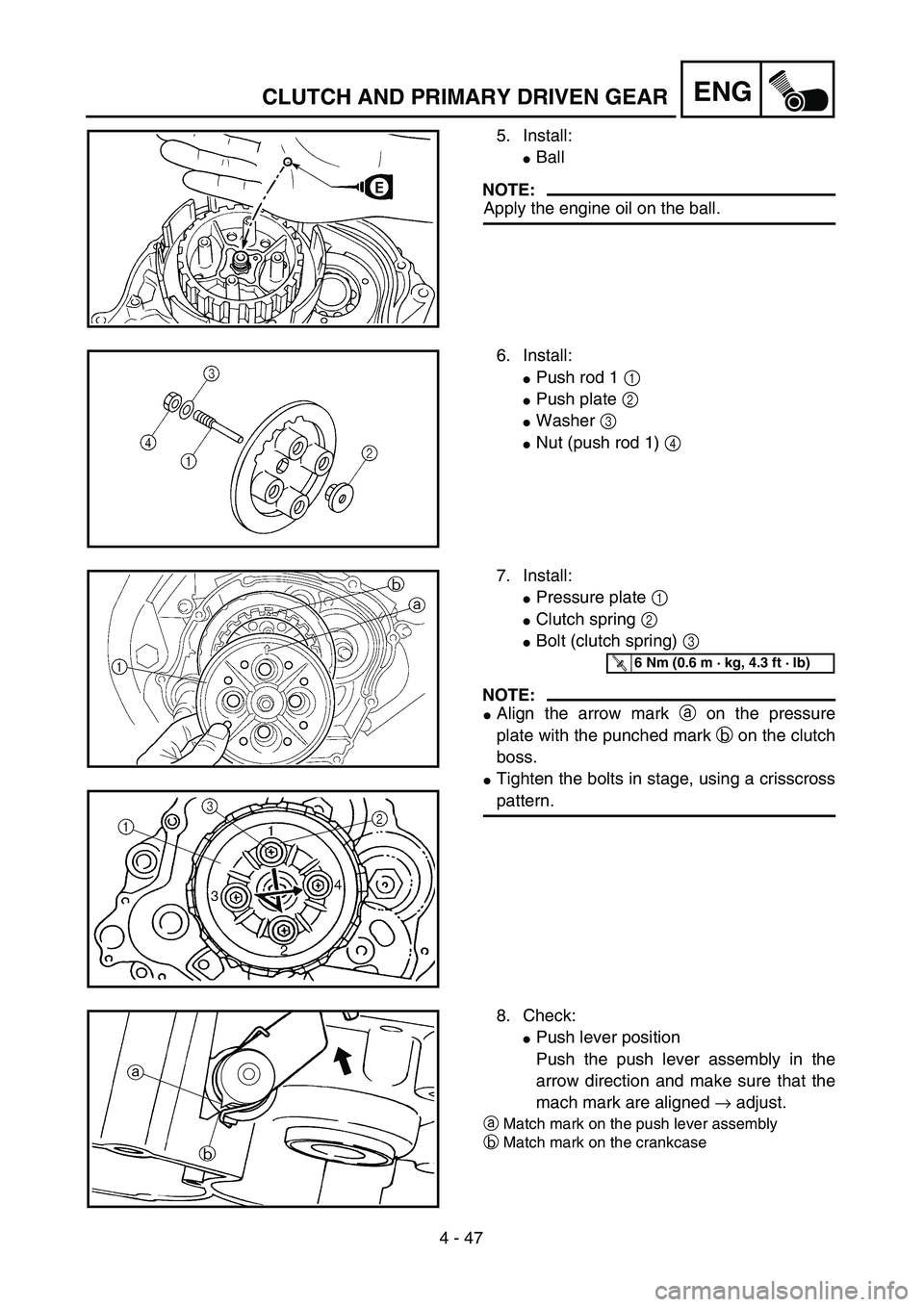
ENGCLUTCH AND PRIMARY DRIVEN GEAR
5. Install:
�Ball
NOTE:
Apply the engine oil on the ball.
6. Install:
�Push rod 1 1
�Push plate 2
�Washer 3
�Nut (push rod 1) 4
7. Install:
�Pressure plate 1
�Clutch spring 2
�Bolt (clutch spring) 3
NOTE:
�Align the arrow mark a on the pressure
plate with the punched mark b on the clutch
boss.
�Tighten the bolts in stage, using a crisscross
pattern.
T R..6 Nm (0.6 m · kg, 4.3 ft · lb)
8. Check:
�Push lever position
Push the push lever assembly in the
arrow direction and make sure that the
mach mark are aligned → adjust.
aMatch mark on the push lever assembly
bMatch mark on the crankcase
Page 384 of 610
 4 - 63
ENG
CDI MAGNETO AND STARTER CLUTCH
(TT-R125E/TT-R125LWE)
3. Check:
�Starter clutch operation
�Install the starter clutch drive gear 1 onto
the starter clutch 2 and hold the starter
clutch.
�Whe")
4 - 63
ENG
CDI MAGNETO AND STARTER CLUTCH
(TT-R125E/TT-R125LWE)
3. Check:
�Starter clutch operation
�Install the starter clutch drive gear 1 onto
the starter clutch 2 and hold the starter
clutch.
�When turning the starter clutch drive gear
counterclockwise ı, the starter clutch and
the starter clutch drive gear should
engage. If the starter clutch drive gear and
starter clutch do not engage, the starter
clutch is faulty and must be replaced.
�When turning the starter clutch drive gear
clockwise Å, it should turn freely.
If the starter clutch drive gear does not
turn freely, the starter clutch is faulty and
must be replaced.
Å
ı
1
2
EC4L5000
ASSEMBLY AND INSTALLATION
CDI magneto
1. Install:
�Stator 1
�Bolt (stator)
�Lead guide
�Screw (lead guide) 2
�Pickup coil 3
�Bolt (pickup coil)
T R..10 Nm (1.0 m · kg, 7.2 ft · lb)LT
T R..7 Nm (0.7 m · kg, 5.1 ft · lb)LT
T R..10 Nm (1.0 m · kg, 7.2 ft · lb)LT
2. Install:
�Stater idle gear 1
�Plate 2
�Bolt 3
�Washer 4
NOTE:
Apply the engine oil on the starter idle gear
inner circumference.
4
1
2
3
ET R..7 Nm (0.7 m · kg, 5.1 ft · lb)
Page 424 of 610
4 - 83
ENGTRANSMISSION, SHIFT CAM AND SHIFT FORK
Shift cam and shift fork
1. Install:
�Shift fork 1 (L) 1
�Shift fork 2 (C) 2
�Shift fork 3 (R) 3
NOTE:
�Mesh the shift fork #1 (L) with the 2nd wheel
gear and #3 (R) with the 4th wheel gear on
the drive axle.
�Mesh the shift fork #2 (C) with the 3rd pinion
gear on the main axle.
2. Install:
�Shift cam 1
NOTE:
Apply the engine oil on the shift cam.
3. Install:
�Shift fork guide bar 1 (short) 1
�Shift fork guide bar 2 (long) 2
NOTE:
�Apply the engine oil on the guide bars.
�Be sure the long bar is inserted into the shift
forks #1 and #3 and the short one into #2.
4. Check:
�Shifter operation
�Transmission operation
Unsmooth operation → Repair.
Page 480 of 610
5 - 28
CHASREAR WHEEL AND REAR BRAKE
4. Inspect:
�Brake drum inner surface.
Oil/scratches → Remove.
OilUse a rag soaked in lac-
quer thinner or a solvent.
ScratchesUse a emery cloth (lightly
and evenly polishing).
ASSEMBLY AND INSTALLATION
Brake shoe plate assembly
1. Install:
�Brake camshaft 1
NOTE:
Apply the lithium soap base grease on the
brake camshaft.
2. Check:
�Brake camshaft operation
Unsmooth operation → Repair.
3. Install:
�Wear indicator plate 1
NOTE:
When installing the wear indicator plate to the
brake camshaft align the projection a on the
wear indicator plate with the slots b on the
brake camshaft.
4. Install:
�Brake camshaft lever 1
NOTE:
Install the brake camshaft lever in relation to
the punch mark a as shown.
T R..10 Nm (1.0 m · kg, 7.2 ft · lb)
Page 502 of 610
5 - 39
CHASFRONT FORK
7. Install:
�Dust seal 1
NOTE:
Apply the lithium soap base grease on the
inner tube.
8. Check:
�Inner tube smooth movement
Tightness/binding/rough spots →
Repeat the steps 2 to 7.
9. Compress the front fork fully.
10. Fill:
�Front fork oil 1
CAUTION:
�Be sure to use recommended fork oil. If
other oils are used, they may have an
excessively adverse effect on the front
fork performance.
�Never allow foreign materials to enter the
front fork.
11. After filling, pump the inner tube slowly
up and down more than 10 times to dis-
tribute the fork oil.
Recommended oil:
Fork oil 10W or equivalent
Quantity (each front fork leg):
TT-R125/TT-R125E:
159 cm
3
(5.60 Imp oz, 5.38 US oz)
TT-R125LW:
156 cm
3
(5.49 Imp oz, 5.27 US oz)
TT-R125LWE:
158 cm
3
(5.56 Imp oz, 5.34 US oz)