Page 41 of 92

OPERATION AND IMPORTANT RIDING POINTS
5-4
2
3
4
56
7
8
9
EAU16841
Engine break-in
There is never a more important period
in the life of your engine than the period
between 0 and 1600 km (1000 mi). For
this reason, you should read the follow-
ing material carefully.
Since the engine is brand new, do not
put an excessive load on it for the first
1600 km (1000 mi). The various parts in
the engine wear and polish themselves
to the correct operating clearances.
During this period, prolonged full-throt-
tle operation or any condition that might
result in engine overheating must be
avoided.
EAU34320
0–1000 km (0–600 mi)
Avoid prolonged operation above
4000 r/min.
1000–1600 km (600–1000 mi)
Avoid prolonged operation above
6000 r/min.
CAUTION:
ECA12930
After 1000 km (600 mi) of operation,be sure to replace the engine oil, fi-
nal transmission oil and the oil filter
element.
1600 km (1000 mi) and beyond
The vehicle can now be operated nor-
mally.
CAUTION:
ECA10310
�
Keep the engine speed out of
the tachometer red zone.
�
If any engine trouble should oc-
cur during the engine break-in
period, immediately have a
Yamaha dealer check the vehi-
cle.
EAU17212
Parking
When parking, stop the engine, and
then remove the key from the main
switch.
WARNING
EWA10310
�
Since the engine and exhaust
system can become very hot,
park in a place where pedestri-
ans or children are not likely to
touch them.
�
Do not park on a slope or on soft
ground, otherwise the vehicle
may overturn.
CAUTION:
ECA10380
Never park in an area where there
are fire hazards such as grass or
other flammable materials.
Page 42 of 92

6-1
1
2
3
4
5
6
7
8
9
PERIODIC MAINTENANCE AND MINOR REPAIR
EAU17280
Safety is an obligation of the owner. Pe-
riodic inspection, adjustment and lubri-
cation will keep your vehicle in the
safest and most efficient condition pos-
sible. The most important points of in-
spection, adjustment, and lubrication
are explained on the following pages.
The intervals given in the periodic
maintenance and lubrication chart
should be simply considered as a gen-
eral guide under normal riding condi-
tions. However, DEPENDING ON THE
WEATHER, TERRAIN, GEOGRAPHI-
CAL LOCATION, AND INDIVIDUAL
USE, THE MAINTENANCE INTER-
VALS MAY NEED TO BE SHORT-
ENED.
WARNING
EWA10320
If you are not familiar with mainte-
nance work, have a Yamaha dealer
do it for you.
WARNING
EWA10330
This scooter is designed for use on
paved roads only. If this scooter isoperated in abnormally dusty, mud-
dy or wet conditions, the air filter el-
ement should be cleaned or
replaced more frequently, otherwise
rapid engine wear may result. Con-
sult a Yamaha dealer for proper
maintenance intervals.
EAU17501
Owner’s tool kit
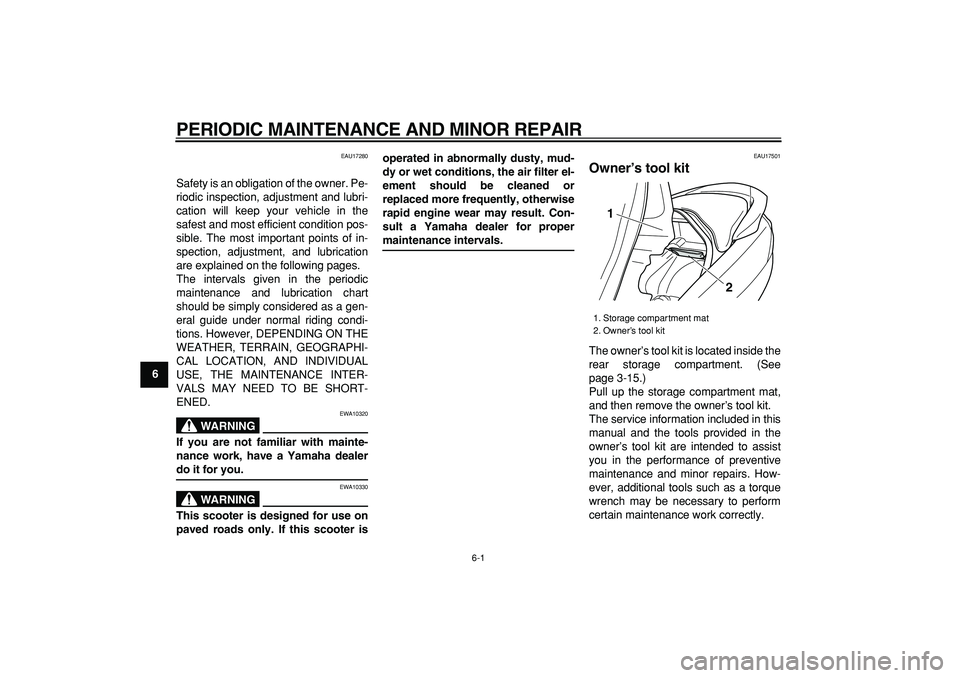
The owner’s tool kit is located inside the
rear storage compartment. (See
page 3-15.)
Pull up the storage compartment mat,
and then remove the owner’s tool kit.
The service information included in this
manual and the tools provided in the
owner’s tool kit are intended to assist
you in the performance of preventive
maintenance and minor repairs. How-
ever, additional tools such as a torque
wrench may be necessary to perform
certain maintenance work correctly.
1. Storage compartment mat
2. Owner’s tool kit
1
2
Page 43 of 92
PERIODIC MAINTENANCE AND MINOR REPAIR
6-2
2
3
4
5
67
8
9
NOTE:
If you do not have the tools or experi-
ence required for a particular job, have
a Yamaha dealer perform it for you.
WARNING
EWA10350
Modifications not approved by
Yamaha may cause loss of perfor-
mance and render the vehicle un-
safe for use. Consult a Yamaha
dealer before attempting any chang-
es.
Page 57 of 92

PERIODIC MAINTENANCE AND MINOR REPAIR
6-16
2
3
4
5
67
8
9
WARNING
EWA11310
�
Make sure that no foreign mate-
rial enters the final transmission
case.
�
Make sure that no oil gets on the
tire or wheel.
7. Check the final transmission case
for oil leakage. If oil is leaking,
check for the cause.
EAU20070
Coolant
The coolant level should be checked
before each ride. In addition, the cool-
ant must be changed at the intervals
specified in the periodic maintenance
and lubrication chart.
EAU34191
To check the coolant level
1. Place the vehicle on a level sur-
face and hold it in an upright posi-
tion.
NOTE:
�
The coolant level must be checked
on a cold engine since the level
varies with engine temperature.
�
Make sure that the vehicle is posi-
tioned straight up when checking
the coolant level. A slight tilt to the
side can result in a false reading.
2. Pull up the right floorboard mat as
shown.3. Remove the coolant reservoir cov-
er by removing the screw.
4. Check the coolant level in the cool-
ant reservoir.
1. Right floorboard mat
1. Screw
2. Coolant reservoir cover
1
1
2
Page 58 of 92

PERIODIC MAINTENANCE AND MINOR REPAIR
6-17
1
2
3
4
5
6
7
8
9
NOTE:
The coolant should be between the
minimum and maximum level marks.
5. If the coolant is at or below the
minimum level mark, open the
coolant reservoir cap, add coolant
to the maximum level mark, and
then close the coolant reservoir
cap.
CAUTION:
ECA10470
�
If coolant is not available, use
distilled water or soft tap water
instead. Do not use hard water
or salt water since it is harmful
to the engine.
�
If water has been used instead
of coolant, replace it with cool-
ant as soon as possible, other-
wise the engine may not be
sufficiently cooled and the cool-ing system will not be protected
against frost and corrosion.
�
If water has been added to the
coolant, have a Yamaha dealer
check the antifreeze content of
the coolant as soon as possible,
otherwise the effectiveness of
the coolant will be reduced.
WARNING
EWA10380
Never attempt to remove the radiator
cap when the engine is hot.
6. Install the coolant reservoir cover
by installing the screw.
7. Place the right floorboard mat in
the original position.
NOTE:
�
The radiator fan is automatically
switched on or off according to the
coolant temperature in the radia-
tor.
�
If the engine overheats, see page
6-37 for further instructions.
1. Minimum level mark
2. Maximum level mark
3. Coolant reservoir cap
Coolant reservoir capacity (up to the
maximum level mark):
0.32 L (0.34 US qt) (0.28 Imp.qt)
1
2
3
Page 62 of 92

PERIODIC MAINTENANCE AND MINOR REPAIR
6-21
1
2
3
4
5
6
7
8
9
EAU21401
Valve clearance
The valve clearance changes with use,
resulting in improper air-fuel mixture
and/or engine noise. To prevent this
from occurring, the valve clearance
must be adjusted by a Yamaha dealer
at the intervals specified in the periodic
maintenance and lubrication chart.
EAU33600
Tires
To maximize the performance, durabil-
ity, and safe operation of your vehicle,
note the following points regarding the
specified tires.
Tire air pressure
The tire air pressure should be checked
and, if necessary, adjusted before each
ride.
WARNING
EWA10500
�
The tire air pressure must be
checked and adjusted on cold
tires (i.e., when the temperature
of the tires equals the ambient
temperature).
�
The tire air pressure must be ad-
justed in accordance with the
riding speed and with the total
weight of rider, passenger, car-
go, and accessories approved
for this model.
WARNING
EWA11200
Because loading has an enormous
impact on the handling, braking,
performance and safety characteris-
tics of your vehicle, you should keep
the following precautions in mind.
�
NEVER OVERLOAD THE VEHI-
CLE! Operation of an overload-
ed vehicle may result in tire
damage, loss of control, or se-
vere injury. Make sure that the
total weight of rider, passenger,
cargo, and accessories does
Tire air pressure (measured on cold
tires):
0–90 kg (0–198 lb):
Front:
200 kPa (29 psi) (2.00 kgf/cm
2
)
Rear:
250 kPa (36 psi) (2.50 kgf/cm
2
)
90–194 kg (198–428 lb):
Front:
200 kPa (29 psi) (2.00 kgf/cm
2
)
Rear:
250 kPa (36 psi) (2.50 kgf/cm
2
)
Maximum load*:
194 kg (428 lb)
* Total weight of rider, passenger, car-
go and accessories
Page 63 of 92

PERIODIC MAINTENANCE AND MINOR REPAIR
6-22
2
3
4
5
67
8
9 not exceed the specified maxi-
mum load for the vehicle.
�
Do not carry along loosely
packed items, which can shift
during a ride.
�
Securely pack the heaviest
items close to the center of the
vehicle and distribute the
weight evenly on both sides.
�
Adjust the tire air pressure with
regard to the load.
�
Check the tire condition and air
pressure before each ride.
Tire inspection
The tires must be checked before eachride. If the center tread depth reaches
the specified limit, if the tire has a nail or
glass fragments in it, or if the sidewall is
cracked, have a Yamaha dealer re-
place the tire immediately.
NOTE:
The tire tread depth limits may differ
from country to country. Always comply
with the local regulations.
Tire information
This model is equipped with tubeless
tires.
WARNING
EWA10470
�
Have a Yamaha dealer replace
excessively worn tires. Besides
being illegal, operating the vehi-
cle with excessively worn tires
decreases riding stability and
can lead to loss of control.
�
The replacement of all wheel
and brake related parts, includ-
ing the tires, should be left to a
Yamaha dealer, who has the
necessary professional knowl-
edge and experience.
1. Tire sidewall
2. Tire tread depth
12
Minimum tire tread depth (front and
rear):
1.6 mm (0.06 in)
Front tire:
Size:
120/80-14M/C 58S
Manufacturer/model:
IRC/MB67
DUNLOP/D305FL
Rear tire:
Size:
150/70-13M/C 64S
Manufacturer/model:
IRC/MB67
DUNLOP/D305L
Page 65 of 92

PERIODIC MAINTENANCE AND MINOR REPAIR
6-24
2
3
4
5
67
8
9
brake system.
WARNING
EWA14211
A soft or spongy feeling in the brake
lever can indicate the presence of air
in the hydraulic system. If there is air
in the hydraulic system, have a
Yamaha dealer bleed the system be-
fore operating the vehicle. Air in the
hydraulic system will diminish the
braking performance, which may re-
sult in loss of control and an acci-
dent.
EAU33473
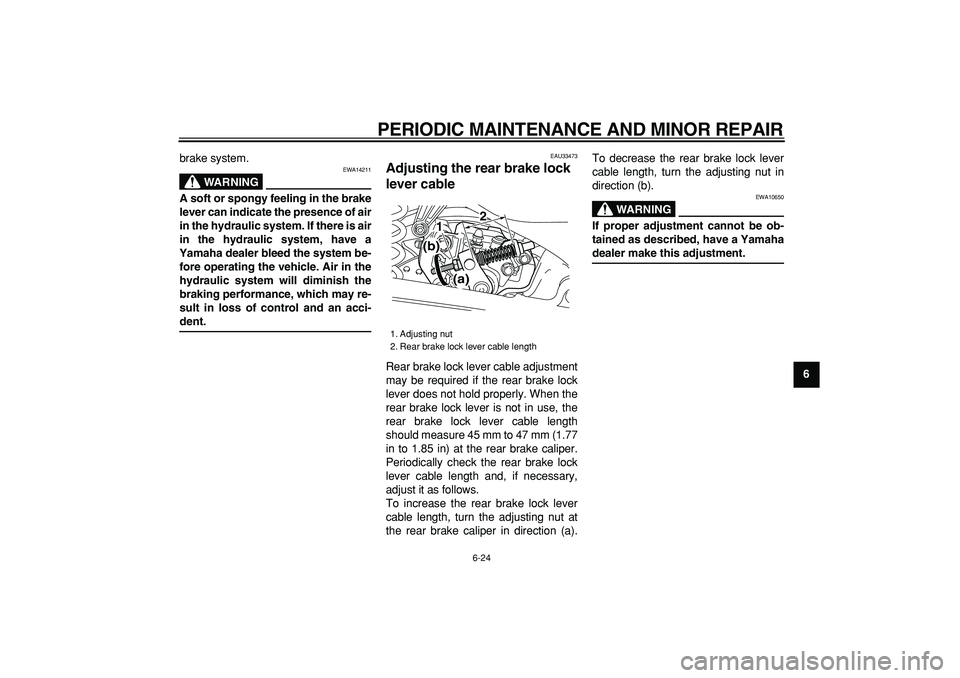
Adjusting the rear brake lock
lever cable
Rear brake lock lever cable adjustment
may be required if the rear brake lock
lever does not hold properly. When the
rear brake lock lever is not in use, the
rear brake lock lever cable length
should measure 45 mm to 47 mm (1.77
in to 1.85 in) at the rear brake caliper.
Periodically check the rear brake lock
lever cable length and, if necessary,
adjust it as follows.
To increase the rear brake lock lever
cable length, turn the adjusting nut at
the rear brake caliper in direction (a).To decrease the rear brake lock lever
cable length, turn the adjusting nut in
direction (b).
WARNING
EWA10650
If proper adjustment cannot be ob-
tained as described, have a Yamaha
dealer make this adjustment.
1. Adjusting nut
2. Rear brake lock lever cable length
1
2
(a) (b)