Page 34 of 100

INSTRUMENT AND CONTROL FUNCTIONS
3-20
3
EAU13220
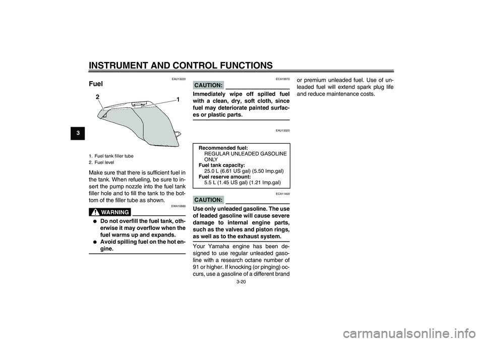
Fuel Make sure that there is sufficient fuel in
the tank. When refueling, be sure to in-
sert the pump nozzle into the fuel tank
filler hole and to fill the tank to the bot-
tom of the filler tube as shown.
WARNING
EWA10880
�
Do not overfill the fuel tank, oth-
erwise it may overflow when the
fuel warms up and expands.
�
Avoid spilling fuel on the hot en-gine.
CAUTION:
ECA10070
Immediately wipe off spilled fuel
with a clean, dry, soft cloth, since
fuel may deteriorate painted surfac-es or plastic parts.
EAU13320
CAUTION:
ECA11400
Use only unleaded gasoline. The use
of leaded gasoline will cause severe
damage to internal engine parts,
such as the valves and piston rings,as well as to the exhaust system.
Your Yamaha engine has been de-
signed to use regular unleaded gaso-
line with a research octane number of
91 or higher. If knocking (or pinging) oc-
curs, use a gasoline of a different brandor premium unleaded fuel. Use of un-
leaded fuel will extend spark plug life
and reduce maintenance costs.
1. Fuel tank filler tube
2. Fuel level
Recommended fuel:
REGULAR UNLEADED GASOLINE
ONLY
Fuel tank capacity:
25.0 L (6.61 US gal) (5.50 Imp.gal)
Fuel reserve amount:
5.5 L (1.45 US gal) (1.21 Imp.gal)
U2D2EAE0.book Page 20 Monday, June 26, 2006 2:55 PM
Page 35 of 100

INSTRUMENT AND CONTROL FUNCTIONS
3-21
3
EAU39450
Fuel tank breather/overflow
hose Before operating the motorcycle:�
Check the fuel tank breather/over-
flow hose connection.
�
Check the fuel tank breather/over-
flow hose for cracks or damage,
and replace it if damaged.
�
Make sure that the end of the fuel
tank breather/overflow hose is not
blocked, and clean it if necessary.
EAU13441
Catalytic converter This vehicle is equipped with catalytic
converters in the exhaust system.
WARNING
EWA10860
The exhaust system is hot after op-
eration. Make sure that the exhaust
system has cooled down before do-ing any maintenance work.CAUTION:
ECA10700
The following precautions must be
observed to prevent a fire hazard or
other damages.�
Use only unleaded gasoline.
The use of leaded gasoline will
cause unrepairable damage to
the catalytic converter.
�
Never park the vehicle near pos-
sible fire hazards such as grass
or other materials that easily
burn.
�
Do not allow the engine to idletoo long.
EAU39491
Seats Passenger seat
To remove the passenger seat1. Insert the key into the seat lock,
and then turn it counterclockwise.
2. Lift the front of the passenger seat
and pull it forward.
To install the passenger seat1. Insert the projections on the rear of
the passenger seat into the seat
holders as shown, and then push
the front of the seat down to lock it
in place.
1. Fuel tank breather/overflow hose
1. Passenger seat lock
2. Unlock.
U2D2EAE0.book Page 21 Monday, June 26, 2006 2:55 PM
Page 40 of 100

INSTRUMENT AND CONTROL FUNCTIONS
3-26
3
CAUTION:
ECA11800
Do not place heat-sensitive items in
the accessory box. The accessory
box gets extremely hot especiallywhen the engine is running or is hot.
WARNING
EWA11421
�
Do not exceed the load limit of
0.3 kg (0.66 lb) for the accessory
box.
�
Do not exceed the maximum
load of 208 kg (459 lb) for the ve-hicle.
EAU39610
Adjusting the headlight
beams The headlight adjusting knobs are used
to raise or lower the height of the head-
light beams. It may be necessary to ad-
just the headlight beams to increase
visibility and help prevent blinding on-
coming drivers when carrying more or
less load than usual. Obey local laws
and regulations when adjusting the
headlights.
To raise the headlight beams, turn the
knobs in direction (a). To lower the
headlight beams, turn the knobs in di-
rection (b).
EAU39641
Handlebar position The handlebars can be adjusted to one
of three positions to suit the rider’s pref-
erence. Have a Yamaha dealer adjust
the position of the handlebars.
1. Headlight beam adjusting knob
1. Handlebar
U2D2EAE0.book Page 26 Monday, June 26, 2006 2:55 PM
Page 45 of 100

INSTRUMENT AND CONTROL FUNCTIONS
3-31
3
�
Do not deform or damage the
gas cylinder in any way, as this
will result in poor damping per-
formance.
�
Always have a Yamaha dealerservice the shock absorber.
EAU40501
Grip warmer adjusting knob This vehicle is equipped with grip
warmers, which can only be used when
the engine is running.
Use the grip warmer adjusting knob, lo-
cated near the accessory box, to adjust
the grip warmer temperature.
The grip warmer adjusting knob can be
set between the “LO” and “HI” posi-
tions. To raise the temperature, turn the
knob in direction (a). To lower the tem-
perature, turn the knob in direction (b).
Align the “” mark on the knob with
“OFF” to turn the grip warmers off.
NOTE:When the vehicle is stopped or travel-
ing at extremely low speeds (e.g., in
traffic jams), the grip warmer tempera-
ture is lower than when traveling athigher speeds.CAUTION:
ECA15520
�
Be sure to wear gloves when us-
ing the grip warmers.
�
If the ambient temperature is 20
°C (68 °F) or higher, do not set
the grip warmer adjusting knob
to the “HI” position.
�
If the handlebar grip or throttle
grip becomes worn or damaged,
stop using the grip warmers andreplace the grips.WARNING
EWA14510
Do not turn the grip warmer knobwhile the vehicle is moving.
1.“LO” position
2.“OFF” position
3.“” mark
4. Grip warmer adjusting knob
5.“HI” position
U2D2EAE0.book Page 31 Monday, June 26, 2006 2:55 PM
Page 46 of 100

INSTRUMENT AND CONTROL FUNCTIONS
3-32
3
EAU15301
Sidestand The sidestand is located on the left side
of the frame. Raise the sidestand or
lower it with your foot while holding the
vehicle upright.NOTE:The built-in sidestand switch is part of
the ignition circuit cut-off system, which
cuts the ignition in certain situations.
(See further down for an explanation ofthe ignition circuit cut-off system.)
WARNING
EWA10240
The vehicle must not be ridden with
the sidestand down, or if the side-
stand cannot be properly moved up
(or does not stay up), otherwise the
sidestand could contact the ground
and distract the operator, resulting
in a possible loss of control.
Yamaha’s ignition circuit cut-off
system has been designed to assist
the operator in fulfilling the respon-
sibility of raising the sidestand be-
fore starting off. Therefore, check
this system regularly as describedbelow and have a Yamaha dealer re-
pair it if it does not function proper-
ly.
EAU40521
Ignition circuit cut-off system The ignition circuit cut-off system (com-
prising the sidestand switch and brake
light switches) has the following func-
tions.�
It prevents starting when the side-
stand is up, but neither brake is ap-
plied.
�
It prevents starting when either
brake is applied, but the sidestand
is still down.
�
It cuts the running engine when the
sidestand is moved down.
Periodically check the operation of the
ignition circuit cut-off system according
to the following procedure.WARNING
EWA10260
�
The vehicle must be placed on
the centerstand during this in-
spection.
�
If a malfunction is noted, have a
Yamaha dealer check the sys-tem before riding.
U2D2EAE0.book Page 32 Monday, June 26, 2006 2:55 PM
Page 47 of 100

INSTRUMENT AND CONTROL FUNCTIONS
3-33
3
With the engine turned off:
1. Move the sidestand down.
2. Make sure that the engine stop switch is turned on.
3. Turn the key on.
4. Shift the transmission into the neutral position.
5. Keep the front or rear brake applied.
6. Push the start switch.
Does the engine start?
With the engine still running:
7. Move the sidestand up.
8. Keep the front or rear brake applied.
9. Shift the transmission into gear.
10. Move the sidestand down.
Does the engine stall?
After the engine has stalled:
11. Move the sidestand up.
12. Release the brake.
13. Push the start switch.
Does the engine start?
The system is OK. The vehicle can be ridden.
This check is most reliable if performed with
a warmed-up engine.The neutral, the brake switch or the YCC-S
system may be defective.
The vehicle should not be ridden until
checked by a Yamaha dealer.
The sidestand switch may be defective.
The vehicle should not be ridden until
checked by a Yamaha dealer.
A brake switch may be defective.
The vehicle should not be ridden until
checked by a Yamaha dealer.
NO YES YES NO YES NONOTE:
U2D2EAE0.book Page 33 Monday, June 26, 2006 2:55 PM
Page 48 of 100

INSTRUMENT AND CONTROL FUNCTIONS
3-34
3
EAU39651
Auxiliary DC jack This vehicle is equipped with an auxilia-
ry DC jack in the accessory box.
A 12-V accessory connected to the
auxiliary jack can be used when the key
is in the “ON” position and should only
be used when the engine is running.CAUTION:
ECA15430
The accessory connected to the
auxiliary DC jack should not be used
with the engine turned off, and the
load must never exceed 30 W (2.5 A),
otherwise the battery may dis-charge.
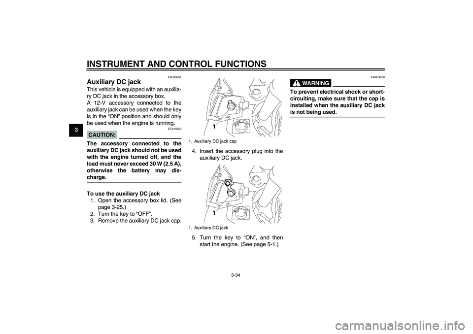
To use the auxiliary DC jack
1. Open the accessory box lid. (See
page 3-25.)
2. Turn the key to “OFF”.
3. Remove the auxiliary DC jack cap.4. Insert the accessory plug into the
auxiliary DC jack.
5. Turn the key to “ON”, and then
start the engine. (See page 5-1.)
WARNING
EWA14360
To prevent electrical shock or short-
circuiting, make sure that the cap is
installed when the auxiliary DC jackis not being used.
1. Auxiliary DC jack cap
1. Auxiliary DC jack
U2D2EAE0.book Page 34 Monday, June 26, 2006 2:55 PM
Page 50 of 100

PRE-OPERATION CHECKS
4-2
4
EAU15603
Pre-operation check list
ITEM CHECKS PAGE
FuelCheck fuel level in fuel tank.
Refuel if necessary.
Check fuel line for leakage.3-20
Engine oilCheck oil level in engine.
If necessary, add recommended oil to specified level.
Check vehicle for oil leakage.6-8
Final gear oilCheck vehicle for oil leakage. 6-10
CoolantCheck coolant level in reservoir.
If necessary, add recommended coolant to specified level.
Check cooling system for leakage.6-12
Front brakeCheck operation.
If soft or spongy, have Yamaha dealer bleed hydraulic system.
Check brake pads for wear.
Replace if necessary.
Check fluid level in reservoir.
If necessary, add recommended brake fluid to specified level.
Check hydraulic system for leakage.6-18, 6-19
Rear brakeCheck operation.
If soft or spongy, have Yamaha dealer bleed hydraulic system.
Check brake pads for wear.
Replace if necessary.
Check fluid level in reservoir.
If necessary, add recommended brake fluid to specified level.
Check hydraulic system for leakage.6-18, 6-19
YCC-S clutchCheck operation.
Check fluid level in reservoir.
If necessary, add recommended fluid to specified level.
Check hydraulic system for leakage.6-18, 6-19
U2D2EAE0.book Page 2 Monday, June 26, 2006 2:55 PM