2006 VOLKSWAGEN GOLF weight
[x] Cancel search: weightPage 347 of 444
Determining correct
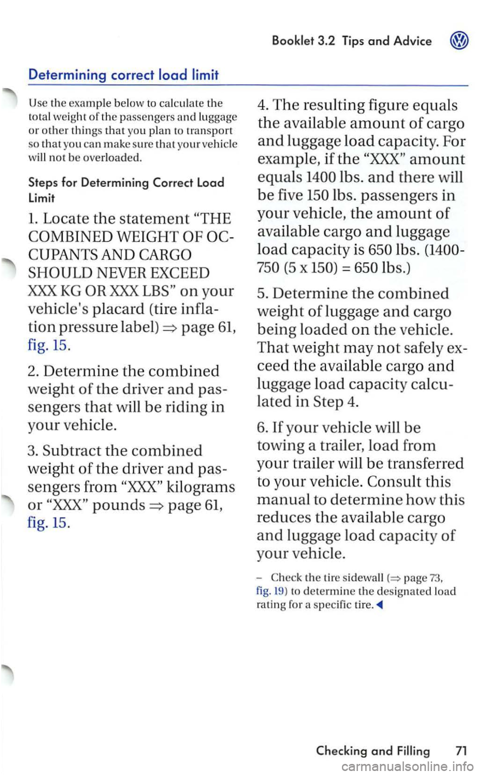
Use the example below to calc ul ate the
to ta l weight of the passen ge rs and lu ggage
or other things that yo u pla n to transport
so that you can make sure tha t
w ill not be overlo ad ed .
Steps for Determining Load
limit
l. Locate the statement
WEIGHT
placard (tire infla
tion
press ure page 61,
fig. 15 .
2. Determine the combined
weight of the dri ver and pas
sengers that will be riding in
your
3. Subtract the combined
weight of the driver and pas
se
ngers from kilog rams
or pounds page 61,
fig. 15.
4. T he resulting figure equals
the availabl e amount of cargo
and luggage load capacity. For
example ,
if the amount
equals
lbs . passengers in
your vehicle, the amount of
availab le cargo and luggag e
lo ad
capacity is lb s.
(5 x = lbs.)
5. Determine the combine d
weight
of lu ggage and cargo
being loaded on the
-the tire page 73,
fig . 19 )
to dete rmine the designated load
ratin g for a specific
and 71
Page 350 of 444
eq uipped with Tire Monitoring
Always buy replacement rad ia l tires that have the same s p ecifica tions as the tires approved for your by
th e original equipment or approved optional tires listed in the page
and its load
limits, and can contribute t o the important road holding, driv ing characteris tics. and safety of the vehi cle. The page 6 1) lists specifications of t h e tires approve d for the Literature.
T he tir e pressure label on the open edge of th e driver's page fig. 15lis ts the s pecifications of the o riginal equipment tires installed o n your ve hicl e at the time it was manufactured.
Federal law requires tire manufacturers to place standardized information on the sidewall of all page fig. 19 . This information identifies and describes the fundamental characteristics, the qualit y grade of the tire and also provides a tire identificatio n number for safety stan dard certification and in case of a recall.
Tir e
specifications
K n
owledge of tire specificatio ns makes it easier to choose the correct tires. Rad ial tires have the
tir e specifications marked on the sidewall, for exampl e:
R 17 91 W
T
his example contains the follow ing informa
t ion:
rat ing letter code
(o r Indicates that the tire has some mud and snow capability
The tires coul d also have the information of direction of page 86.
Speed rating letter code
The speed rati ng letter code o n the wheels indicates the maximum permissible road speeds in o n 77.
up to 93 mph
km/h )
R
up to km/h)
up to mph
mph
krn /h)9l
W
up t o 168 mph
Tire Identification Number and tire manufacture dote
T
his i s the t ire's begi ns with th e letters
mean tha t the tire was produced in th e 18th week
fabric in the tire. In gen the g reater the number o f plies, the m ore weight tire can support. Tir e manufacturers
a lso must indicate the materials in the tire, which include steel, nylon, polyes ter, and others.
system)
For tires with maxim um sp eed over t49 mph (240 le tt ers
74 Checking and
Page 362 of 444
3.2 Tips and Advice
(continued)
knock the vehicle ofT the jack or hid e under a
vehicle.
Never support your body weight on the hicle when it is up on the jack.
Never allow anyone to stay in the vehicle when raising the ve hicle with th e jack or when it is up on the jack.
Never let anyone place any part of their body underneath the ve hicle when supported by th e jack.
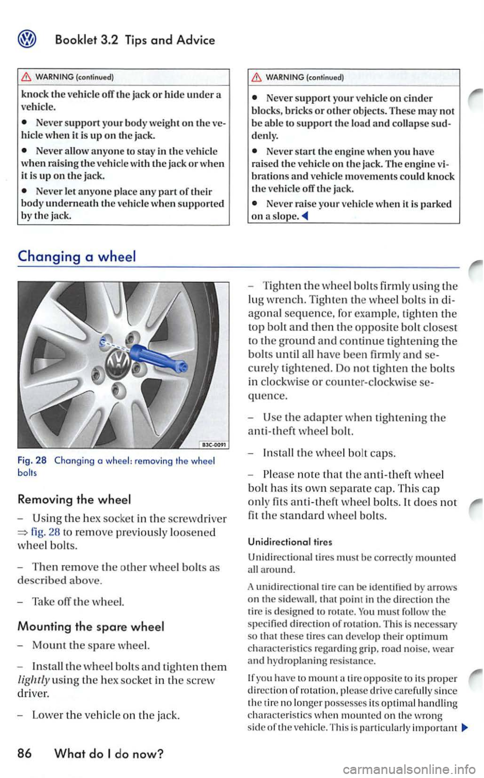
Fig. 28 Changing a wheel: remov ing the wheel
Removing the
U sing the hex socke t in the screwd rive r
fig. 28 to re move pr ev iously loosened
w
hee l bolts.
Then remove th e o ther wheel bolts as
d
escribed above.
Tak e off the w heel.
Mounting the spare
Mount the spare wheel.
In stall the wheel bolts and tight en them
lig hrly using the hex socket in the screw
driv er.
Lower the vehicle on th e jack.
86 What do do now?
(continued)
Ne ver support your vehicle on cinder blo ck s, bricks or ot her objects . These may not
b e abl e to support the load and collapse denl y.
Neve r start th e en gine when you have
rai sed the veh icle on th e jack. The engine brations and ve hicle movements could kno ck
th e ve hicle off the jack.
Neve r raise your ve hicle when it is parked on a s lope .
Tighten the w hee l bolt s firml y using th e
lug wre n ch. Tighten
the w heel bolt s in
agonal sequence, fo r exa mple, tighten the
top bolt and then the opposite bolt closest
to th e ground and continue tight ening the
bolts until all have been firmly and
quence.
Use the adapter w hen tight enin g th e
anti-theft wheel bolt.
In stall the w heel bolt caps.
note that the anti-theft w heel
bolt h
as its ow n separate cap. This ca p
o nl y
fits whee l bolts. It does not
fit the standard wheel bolt s.
Unidirectional tires
Unidirectiona l tires must be correctl y mount ed
all around.
A unidir
ectional tire can
must follow the specifie d direction of ro tatio n. T his is necessary
s o these tire s can deve lop their optimum chara cte ristics regard ing gr ip. road noise. wear and hydroplaning resis ta nce.
you have to mount tir e opposite to its proper d ire ction of rotati on, please drive carefull y since
th e tir e no lo ng er posse sses its optimal ha ndlin g
c h arac te rist i
cs when mounted on th e wro ng
s id e of th e ve hicl e. T hi s is particu larly impo rtant
Page 382 of 444
3.2 Tips and Advice
To prevent the underbody of the hicle when liftin g the vehicle. rubber pads must be u sed.
Befor e dri v
ing onto floor jack, you must check
to make sure that there is enough clearance tween low parts of the ve hicle and the floor jack.
liftin g your vehicl e with a floor
jack can cause the vehi cle to fall off the floor jack and cause serious personal injury:
Always lift your vehicl e only a t the nated lift points shown in the illustrations.
Never allow a n yo ne to stay in the ve hicle when it is bein g lift ed or w he n it is orr the ground.
No t using the desig na ted lift poin ts can cause t h e ve hicl e to fall orr the floor jack when heavy parts su ch as the engin e o r sion removed.
should also notify Vol k swage n of
America,
Addre ss of N
Tel.:
do now?
(continued)
on a floor jack, always make sure that the ve hicl e
i s s afe ly supported on s afety stands intended for that purpose that arc strong enoug h to support the weight of the vehi cle.
Always make sur e that the weight of the
hicle is not heavier than the lifting capacity of the floor jack and safety stands being used.
Neve r start th e engin e w hen you have raised the vehicle on the floor jack. The en gine
vibrations and vehicle move ments could knock the vehi cle orr the floor jack.
Note
Lifting your vehicle any points other than the designated lifting points can cause serious
driving your vehicle on to a hoist,
make sure there is s uffi cient clearance between the hoi st and b ottom of the ve hicle.
From Monday through
Frida y
have a loo k at:
http://www-odi. nhtsa.dot. gov/ ivo q/
and print out the web form and fax it
mail it to:
Department of T ran sp o rtation
National Highway Safe ty Admin is trati on of Defect s 7th
Page 396 of 444
Identification No.
Type code number I designation Engin e
output in kilowa tts
Eng in e and transmission code le tter I Paint
n o. I Interior
Op tional equipment numbers
You can also find data in your Maintenance booklet.
3.3
S to p ! Befor e working in th e e ngine compart
ment , a lways read and heed all warnings bookle t3.2 and chap te r
is p ote ntially da ngerous area and ca n cause se
riou s personal injury.
Rating and th e Gros s Axle Rating for front and rear are lis ted on a sticker on the
inclu des the weight oft he basic ve hicle plus full fuel tank, oil coola nt , p lu s maximum load, which combines passenge r lb s I 68 kg per designate d
sea ting posit ion ) and luggage weig ht.
Luggage carry ing ca pacity is not increase d by the use of a roof rack , unl ess th e passenger ca
paci ty is reduced accordin g ly.
The Gross Axle Rati ng is th e maximum
load that can be applied at each ax le of th e ve
hicl e.
Exceeding the m aximum permissib le weight ra tin gs ca n result in accidents leading to se
riou s personal injury.
Never let the actual G ross Axle Ratin g excee d the permissibl e weight s. Also neve r le t t11eir combination excee d th e Gross Ratin g.
Always remember that th e vehicle's ha n
dlin g will be by th e extra load. There
fore , adjust yo ur speed accordin gly.
Exceeding permi ssibl e we ight ratings can
re sult in damage, acc ident s and personal injury.
Note
Th e veh icle ca pacity we ig ht figures apply
w hen th e load is dis trib uted eve nly in the vehicle (pas sengers and luggag e). trans
po rtin g a heavy load in the lu ggage compartment , carry the lo ad as near to th e rear as
p oss ible so th at t he vehicle's handling is not im
p a ire d.
Always observe local regulations.
Page 397 of 444
permissible roof weig h t is 165lbs (75 kg).
use th e roof rack syste m specifically designed, tested and approved by Volkswagen.
T he roof weig ht i
ncreases th e weight of th e front and rear axle and correspondingl y reduces th e other lo ad that your ve hicle can carry.
D istribu te the load evenly and do no t exc eed the Roof Weig h t (including the we ight of the roof rack syste m ) o r th e Gross weight .
For
more d e ta ils book let2.1 firs t",
c hapte r dri ving" bookle t3. 1 ''Con
tro ls and Equipment" , chapter and storage."
Tran sporti ng heavy bulky loads on th e roof w ill change th e way th e ve hicl e handles by shifting the ve hicle's center of gravity, changing its aerod ynamics and the way it r eacts to side winds.
Dimensions
T he s pecificatio ns refe r to the basic model. Dif
f erences may occur dependin g on the model
type and optio ns o rd ere d, fo r exa mple. tire s izes.
be careful when parking your vehicl e
i n areas with parking barriers or c u rbs. barriers and cu rbs vary in heig ht. They could damage your bumper
(continued)
t hat is large, heavy, bulky, long or
Always adapt your driving a nd speed to
w hat yo u arc carryi ng on th e roof as well as to
road , traffi c, weath er and wind co nd it io ns.
A lways avoid sudden brakin g or driving mane uve rs.
A lways make su re th a t loads are properly
d istribute d and that heavier it em s are in th e
fro nt.
Neve r exceed the maximum ro of load for the ve hicle, maximum axle loads or th e maximum gross vehicl e w eigh t.
When drivi ng up steep ramps . o n roug h
road s, over curb s, etc. it is important to remember that some part s of your vehicl e, s u ch as
s poiler s or exhaust sys te m components, may be
close to th e g round. Be ca reful no t damage them.
Tips
The figures may be d ifferent if ad ditio nal equipment is fitt ed, for different models, for special
ve hicles and for ot11er