2006 VOLKSWAGEN GOLF MK5 bulb
[x] Cancel search: bulbPage 17 of 444
Booklet
v
Vehicle Lifting 3.2:
Location 3.2:
Vehicle Weights 3.3: 6
Ventil atio n slit s 2.1:
Volk s wagen Servic e Repair Manuals 3.2 :
w
Warn ing light
3.2: 5
Brake
pads worn 3.2: 2
Brake system 3.2: 2
Bulb failure 3.2:
93
3.2:5
Eng ine hood 3.2:41
Engine oil pressure 3.2: 45
E n
gin e oil se nsor 3.2:44 3.2:9
3.2:7 Exhaust gas syste m 3.2:
Fuel fille r cap 3.2 : 3 5
Gen erat or 3.2: 56 MIL
steering 3.2: 8
Safe ty belts 2.1: 14
mode ls) 3.2 : 62
Wind shi eld washer fluid 3.2 :
Warning light (Ca nada models)
Tire pressure m onitorin g di spla y 3.2: 65
14 Key words
Warn ing light s 3.1: 4
Emergency
flasher 3.1: 45
I n strume nt clus te r 3.1: 4
Washi ng by hand 3.2:22
Wash in g th e ve hicle 3.2: 22
Washin g with power cleaners 3.2: 23
Waxing How often s
hould I wax my car? 3.2: 24
Wear indicator 3.2:
72
Weights 3.3: 3.
What does it mean when I feel a slight vi bra-tion o n the brake pedal ? 3.2: 4
W h
at happens if yo u do not wear your safe ty
b elt ? 2.1: 16
happe n s if you wear yo ur safe ty belt too
l oose?
2.1: 21
happe n s to occupants not wearin g
safe ty belt s? 2.1:
if I purchase poor quality fuel? 3.2: 37
is the correct brake fluid leve l?. 3.2: 53
What is the r ight way to break-in my
ve hicl
e? 3.2: 12
kind of brake fluid should I u se? 3.2: 54
What kind of engine oil should 1 put in my
ve hicle ? 3.2: 42
What should I d o a fter changing a
w heel? 3.2: 69, 87
should I do after re pla cing
wheels? 3.2:
should I do if! want t o add an acces sory
t o my vehic le? 3.2: 31
sh o uld I do if I want to modify m y
ve hicle? 3.2: 32
should I do if I want to re p air my
ve hicle? 3.2: 32
What sh o uld I
do if the brake wa rnin g light
comes on? 3.2: 2, 53
What wou ld
happen if I put leaded gaso line
i n m y car? 3.2: 37
W h
at you must do after reconnect th e battery 3.2: 55
Page 175 of 444
Booklet 3.1 Controls and Equipment
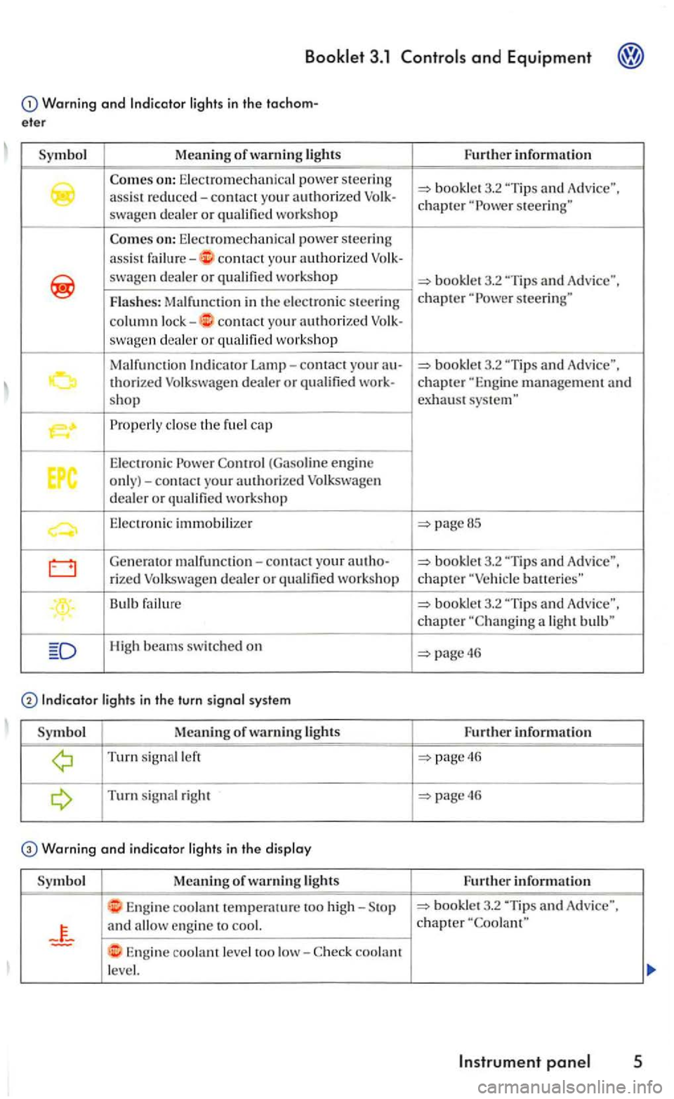
Warning and lights in the tachom
eter
Symbol Meaning of warning lights
swagen dealer or
on: Electromechanical power steeri ng
a
ssi s t contact yo ur a uthorized
swagen d ealer or
contact your authorized swagen dea ler or workshop
Malfunction
Properly close th e fu el cap
Elec tronic Power (Gaso line engine only)-contact your authorized Volkswage n dealer or qualified workshop
E le ctronic immobilizer
Generator malf unction-contact your au tho-
rized Volkswage n dealer or qualified workshop
Bulb failure
High beams swit ched on
Turn signal left
Turn s ignal right
Warning and indicator light s in the di splay
Symbol Meaning of lights
Engine coolant temperature too high-
and
Engine coolant level too low-coolant
le vel. Fu
rther information
3.2
"Tip s and Advice". chapter steering"
steerin g"
pageBS
-
batteries"
booklet 3.2
page46
Further information
page46
page46
Further inform ation
3.2 "Tip s and Adv ice", chapter
Page 369 of 444
Heated seats 4
(5). 37 46 (5)
windows for 23 front
wind ows for 32 rear
Rea r
window de- 25 (25) fogger
R
ear w indow wiper 41 (15)
R ear 12-vo h socket 26
F1 F2
Backup light left F47 F48
Backup light right F47 F48
Brake light left F48
Warning
Brake light righ t F47
Turn sig na l left F47 F48
Turn signal right F47 F48
F48
Headlight left F47
Headli gh t right F48
Horn F5 (15)
Rad i
ator
Radio Fl9 (15)
Sound syste m
Windshield wipers F31
the wrong fuse and attempti ng to re pair a fuse or usi ng something instead of a fuse can
cause a fir e and serious personal injury.
Alway s read and heed the information and all page a
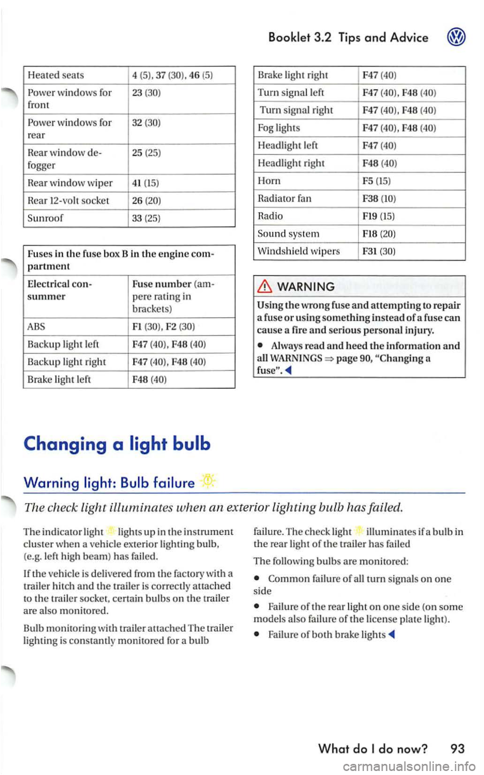
The check light ill uminates when an ex terior lighting bulb has failed.
The indicato r light lig ht s up in the instrument clus ter when a ve hicle exterior lightin g bulb,
(e.g. le ft high beam) has failed.
th e ve hicle is delivered from the factory with a
t railer h itch and the is correct ly atLached to the trai le r socket, cert ain bulb s on the trail er are also monit ore d .
Bu lb
monitorin g with trailer attach ed The traile r light ing is con stamly monitored for a bulb failu
re.
The ch eck ligh t illumin ates if a b ulb in the rea r light of the trailer has fai led
The following bulbs are mon itored:
failure of all turn signa ls on one si de
Failure o f the rear light on one si de (on som e
model s als o failu re of the license pla te light ).
Failure of both brake li gh ts
What do
Page 370 of 444
Booklet 3.2 Tips and Advice
Changing
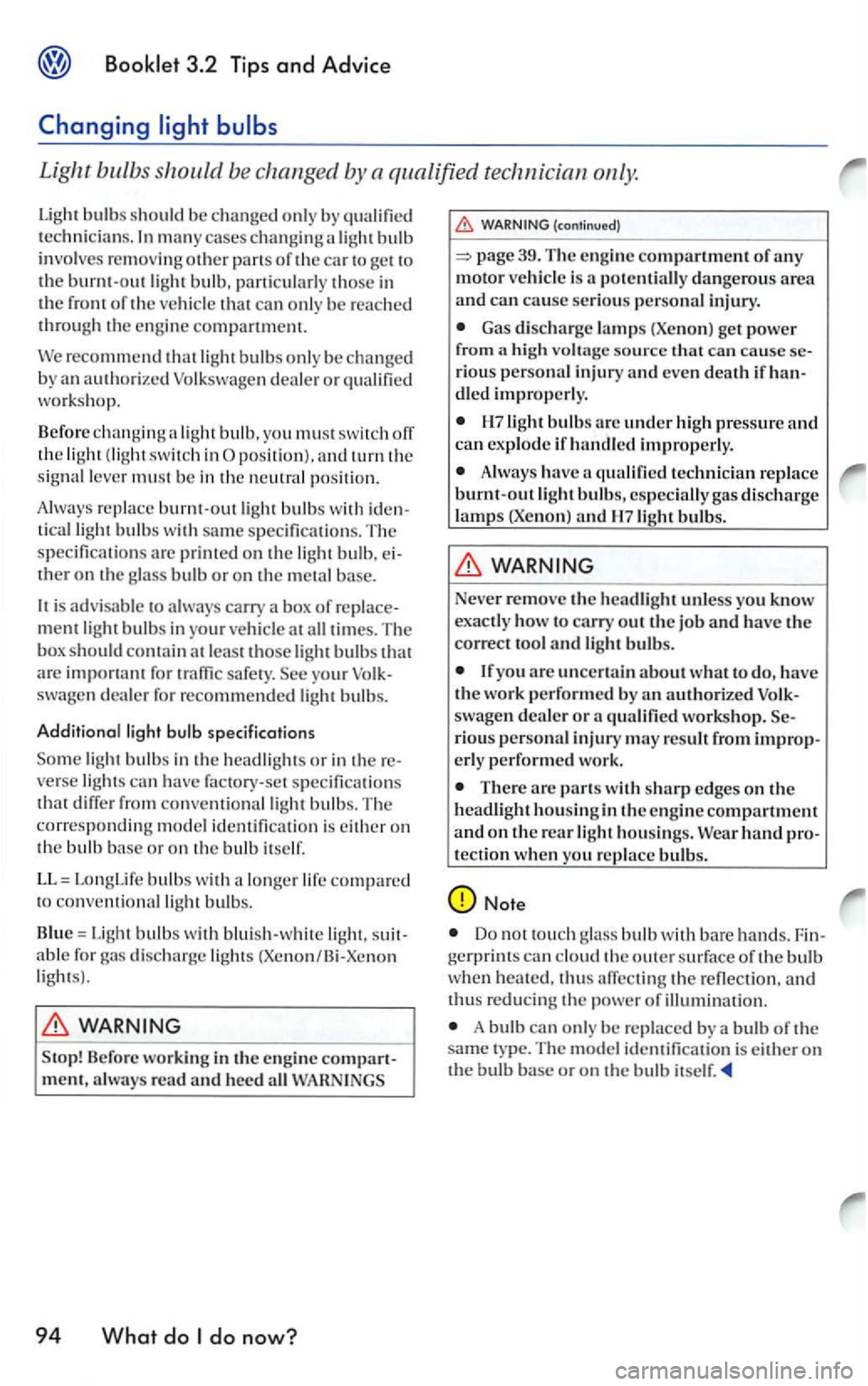
Light bulbs should be changed by a qualified technician
m an y cases changing a light bul b
invol ves remov in g other pa ns of the car to
recommen d light bulbs o nl y be chan ge d
b y an authorized Volkswage n dea le r or qual ified workshop.
Before changin g a light bulb. yo u must sw itch ofT the light (lig ht switch in
tical light bulbs w ith sam e s pecificati o ns. The
s p ecifi catio ns arc prime d on the lig h t bulb . ther on the glass bulb or o n th e m eta l base.
is advi sable to alw ay s carry a box of
for traffi c safe ty. swage n dealer for re comm ended light bulbs.
Additional light specificati o ns
light bulbs in the headli gh ts or in verse lights can hav e fac tory-set s pecifi cntion s that diffe r fro m conventi onnllight bulbs. Th e corresp onding model identifi cation is either on the bulb bas e or on th e bulb itself.
LL = LongLife bulbs w ith a lo nger life compared to con ve ntional light bulb s.
Blue =
Light bulbs w ith blui sh -w hite abl e for di scharge light s (Xenon/Bi-Xcno n light s).
Stop! Before workin g in the engine always read and heed all
94 What do
(cont inued)
page 39. The engine compartment of any motor vehicl e is a p otentiall y dangerous area and can cause serious personal injury.
Gas discharge la m ps (Xen on) get power from a high voltage source that can cause rious personal injury and even death if dled improperly.
bulbs arc under hi gh pressure and can exp lode if handled improperly.
Always have a qualified technician r eplace burnt-out light bulbs, especially gas discharge
lamp s (Xenon) and bulbs.
Neve r remove the headlight unless you know exactly how to carry out the job and have the correct tool and li ght bulbs.
yo u arc uncertain about what to do, have the work performed by an auth orize d swagen d ealer or a qualified workshop. rious personal injury m ay result from erly performe d work.
There arc parts w ith sh arp edges on the headlight h ousin g in the en gi ne compartment and on the rear light h o usings.
Do not touc h glass bulb with bare hands. can clo ud the o uter surface of the bul b when thus afTccting the refle ction , and th us reducing the power of illuminat ion.
A bulb can only be re placed b y a bulb of the sam e ty pe . The m odel identifica tion is either o n the bulb base or on the bulb itself.
Page 371 of 444
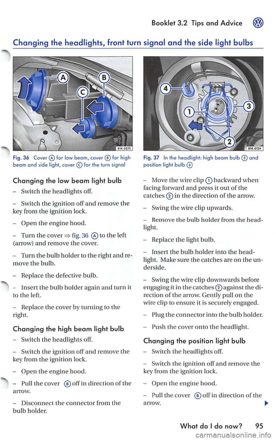
Fig . 36 for high beam and side light ,
th e ignition off and re m ove the
k
ey fro m the ignition lo ck .
-
to the left
(a rrow) a
nd re move the cove r.
- T
urn th e bulb holder t o the right andre
move th e bulb.
- R ep lace th e defec tive bulb.
-
t h e bulb h o ld er again and turn it
t o
the left.
-
Replace t h e cover by turning to th e
rig ht.
the high beam light bulb
-
the ig nition
th e en gin e hood.
-
o ff in direc tio n of the
a rrow.
- Disco
nnect the connec tor fro m the
bulb hold er.
Bookl et 3.2 Tips and Advice
Fig. 37
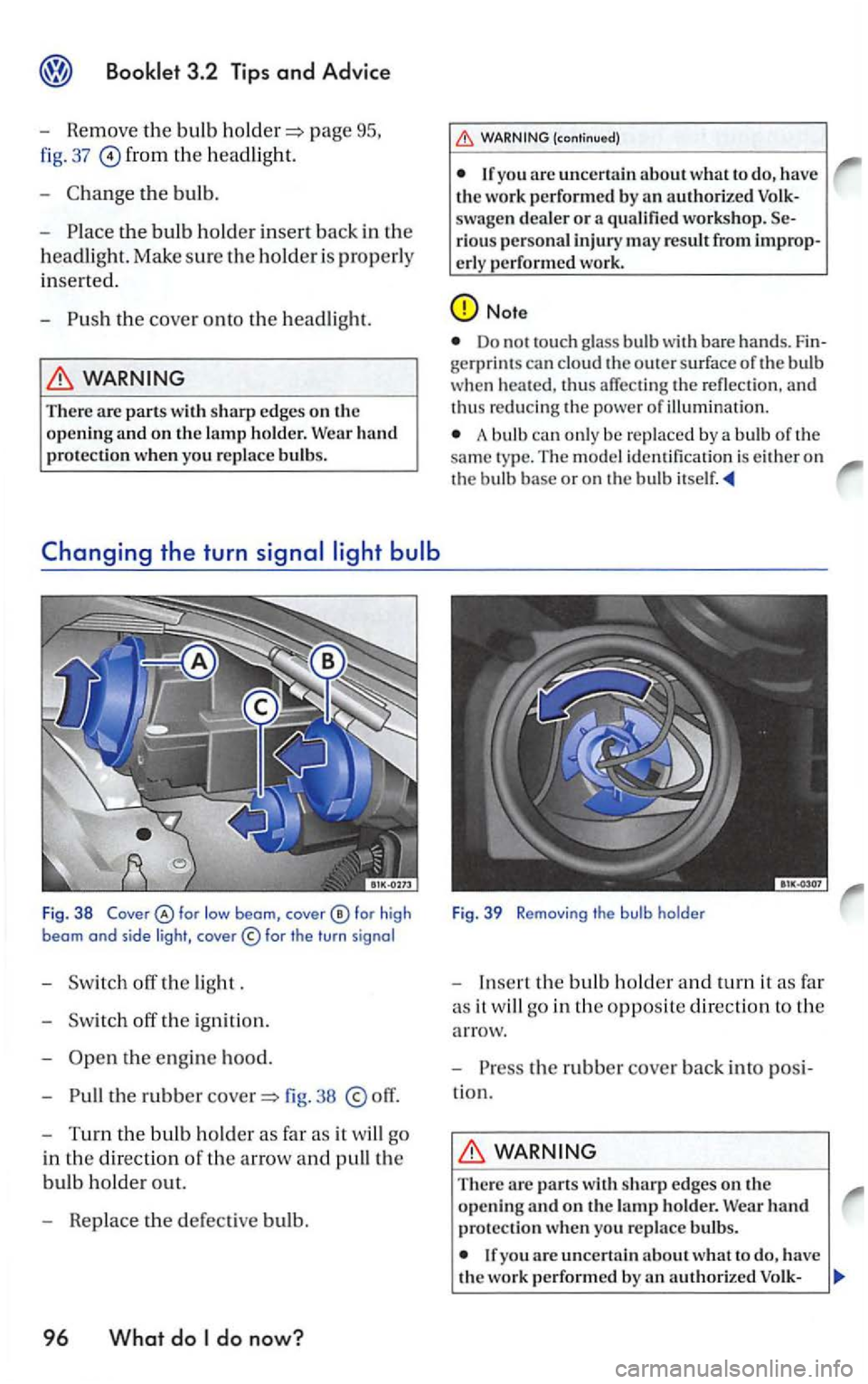
- Move th e wi re cli p backward when
f
acin g forwa rd and press it ou t of the
ca tc h
es in th e di rection of the arrow.
-
the w ire clip upward s.
- Rem ove th e bul b ho ld er fro m the h
ead-
light.
- Repl
ace th e light bu lb .
- In
sert the bulb ho ld er into th e head-
light. Make sure the catches are on th e un
d ers ide.
-
the wire clip downwards befo re
e n
gagin g it in thecatc hes0again sl the di
r
ectio n of th e arrow. Gently pull on th e
wire clip to ensure it is securely e ngage d.
-
th e connector into the bul b ho ld e r.
-
the cove r onto the hea dlight.
the e ngi ne hood.
-
the cove r off in direction of t h e
a rro
w.
What do
Page 372 of 444
page
fig. 37 from the headligh t.
-
the bulb.
-
headlight. Make sure the holder i s properly
inserted.
-
WARNING
There are parts with
the e ngine hood.
-
the rubbe r 38
WARNING (continu ed)
are uncertain about what to the work performed by qualified workshop. riou s personal injury may result from improp-
erly performed work.
Note
Do no t to uch glass bulb with bare hands. gerprint s can cloud the o uter surface of the bulb
whe n thus affectin g th e refl ectio n . and thus reducing th e pow er o f illuminatio n .
A bulb can only be replaced by a bulb of th e
sa me ty p e. The mod el identifica tion is either on
the bulb base or on the bulb
Fig. 39 Re moving the bulb holder
- Insert the bulb h old er and turn it as fa r
a s it w ill go in th e
opposite direct io n to th e
arrow.
-
the rubbe r cover back into
WARNING
The re wit h sharp edges on th e opening
If yo u the work performed by
Page 373 of 444
(continued)
swagen dealer or a qualified workshop. rious personal injury m ay resu lt from erl y perfo rmed work.
Booklet 3.2 Tips and Advice
Note
Do not touch glass bulb with bare hands.
A bulb can on ly be rep laced by a bulb of the same type. The model identification is either on the bulb base or on the bulb
turn
The rear light contains a light bulb fo r the rear turn signal and a light bulb for the
rea r brake light.
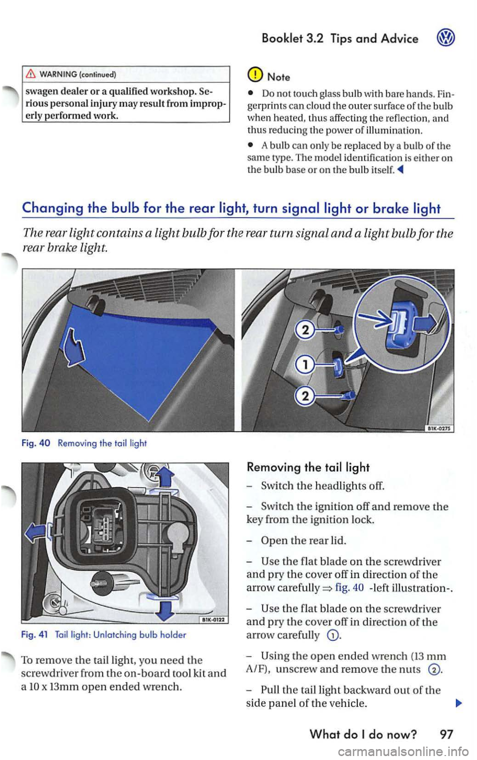
Fig . Removing the toi l ligh t
F ig . 4 1
Toil light: Unlotching bulb holde r
To remov e the tailligh t, yo u need the
screwdr iver from th e
on-board tool kit and
a
x I3mm open ended wrench.
R e moving the
-the headlights off.
-the ign ition off and remove the
key from the ignition lock.
-
the flat blade on th e screw driver
and pry the cover off in direction of th e
arrow
fig. - left illu stration-.
-
the f lat b lade on the sc rewdri ver
and pry the cover off in direction of the
arrow carefully
the open ended wrench (13 mm
A/F), unscrew and remo ve the nut s
the ta illight backward out of the
side panel
of th e veh icle .
What do
Page 374 of 444
-the ta illight remove d from th e
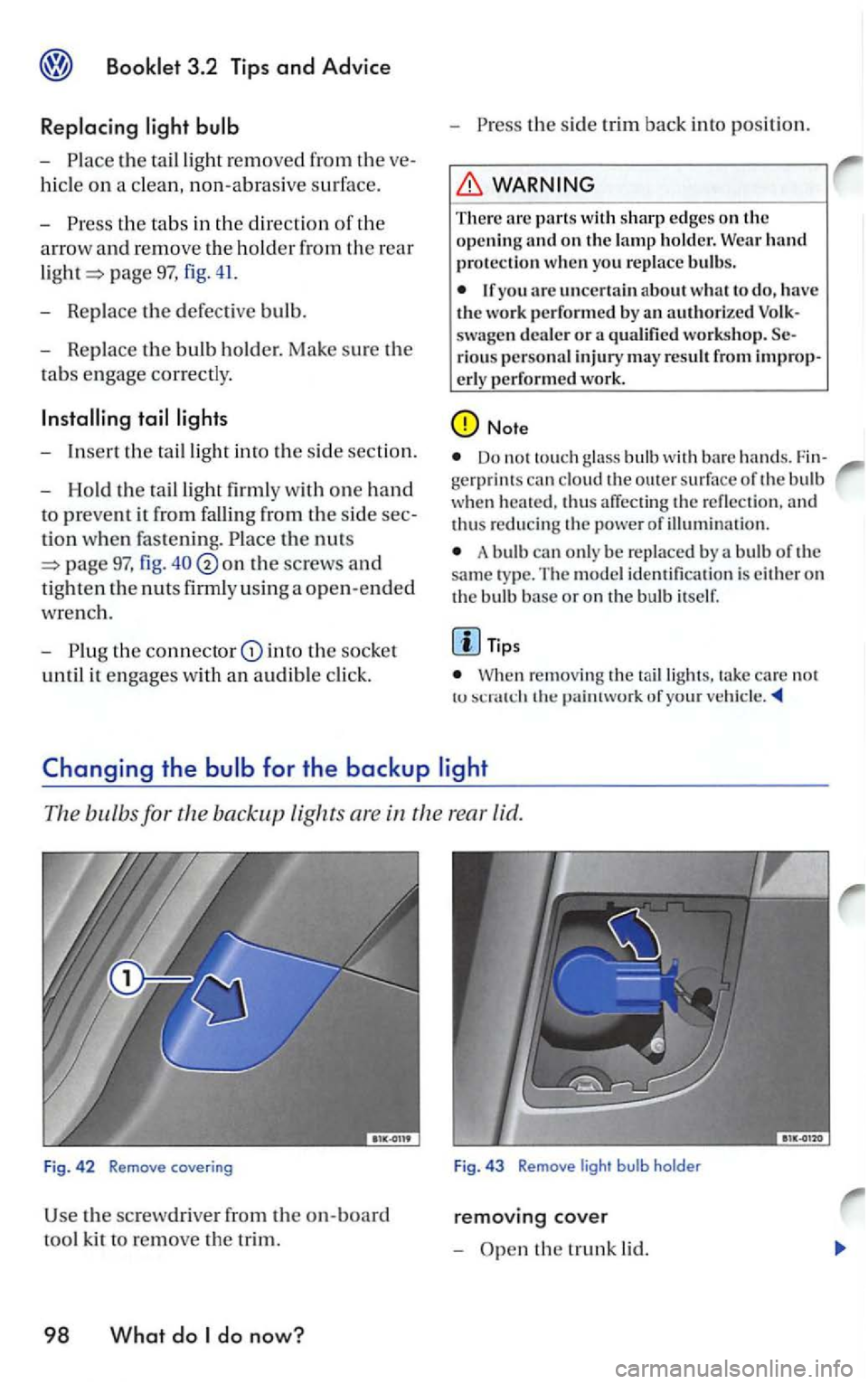
hicle on a clean, non-abrasive s urfac e.
-
t h e tabs in the direction of th e
a rr ow a
nd remove th e holder from the rear
page 97, fig. 41.
- Replace the defectiv e bulb.
- Replace the bulb h old er. Mak e sure the
tabs engage correctly.
- Insert the taillig ht int o the s ide section.
- Hold
the taillight firml y with one hand
to prevent it from fall in g from the sid e
tion when fasten ing.
page 97, fig . on the screw s and
tighten the nuts firml y using a o pen-ended
w re n ch.
-
in to the sock e t
until it engages with an audible click. -
the s
ide trim back into position.
WARNING
There arc parts with sharp edges on the
o pening an d o n the lamp ho ld er. Wear hand protection when yo u bulbs.
an authorized workshop . rio us person al injury may result from
Do not touch the o ut er surface o f the bulb heated. thus of
A bul b only be replaced by a of the same ty pe. The m odel identificatio n is e ither on the bulb base or on the bulb itself.
Tip s
When re m ov in g the take ca re no t tu ofyuu r
bulb
removing cover
-the trunk lid.