Page 1753 of 2000
SEAT BELT – SEAT BELT WARNING SYSTEMSB–15
SB
WIRING DIAGRAM
B129858E01
Page 1756 of 2000
SB–18SEAT BELT – SEAT BELT WARNING SYSTEM
SB
WIRING DIAGRAM
B129859E01
Page 1785 of 2000
EI–14ENGINE IMMOBILISER – ENGINE IMMOBILISER SYSTEM
EI
TERMINALS OF ECU
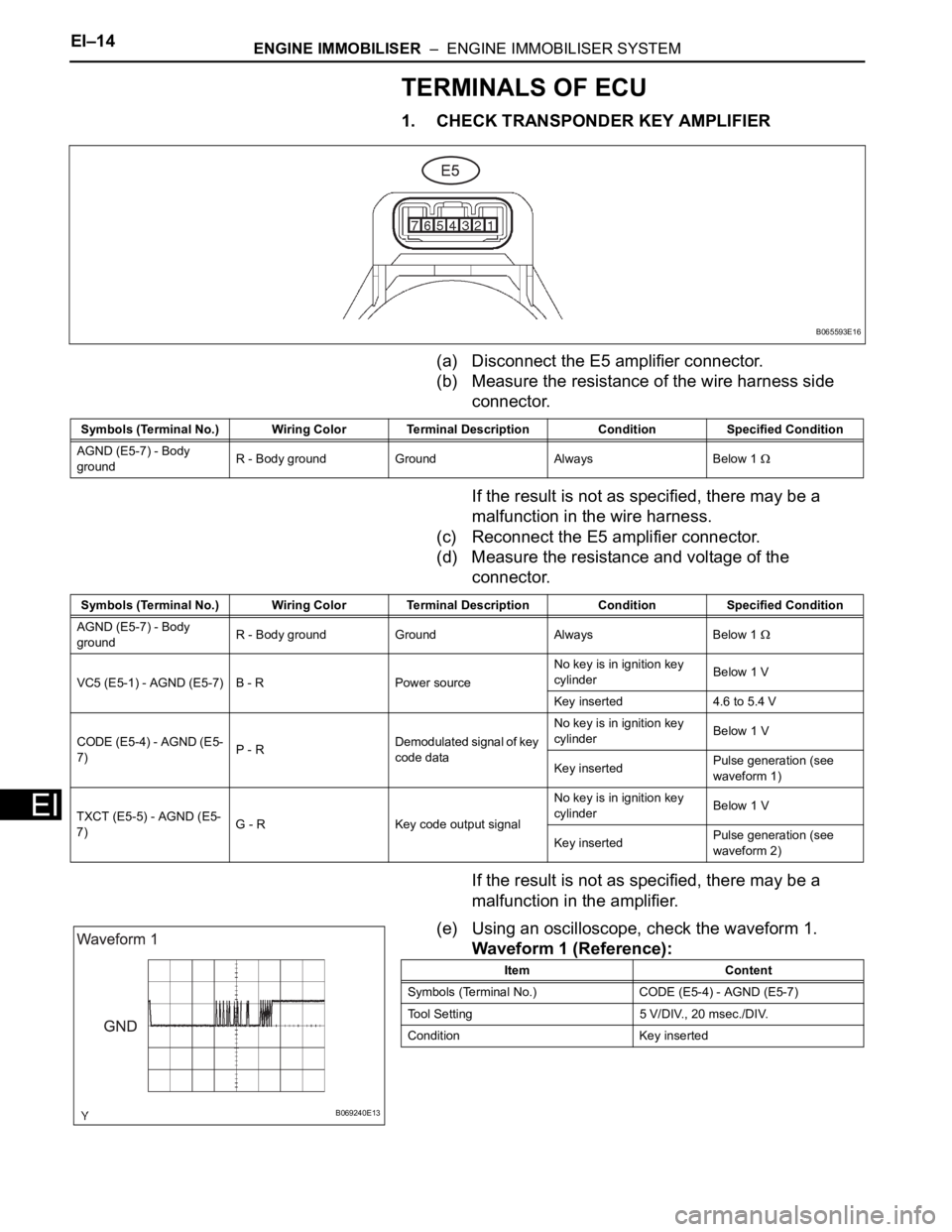
1. CHECK TRANSPONDER KEY AMPLIFIER
(a) Disconnect the E5 amplifier connector.
(b) Measure the resistance of the wire harness side
connector.
If the result is not as specified, there may be a
malfunction in the wire harness.
(c) Reconnect the E5 amplifier connector.
(d) Measure the resistance and voltage of the
connector.
If the result is not as specified, there may be a
malfunction in the amplifier.
(e) Using an oscilloscope, check the waveform 1.
Waveform 1 (Reference):
B065593E16
Symbols (Terminal No.) Wiring Color Terminal Description ConditionSpecified Condition
AGND (E5-7) - Body
groundR - Body ground Ground Always Below 1
Symbols (Terminal No.) Wiring Color Terminal Description ConditionSpecified Condition
AGND (E5-7) - Body
groundR - Body ground Ground Always Below 1
VC5 (E5-1) - AGND (E5-7) B - R Power sourceNo key is in ignition key
cylinder Below 1 V
Key inserted 4.6 to 5.4 V
CODE (E5-4) - AGND (E5-
7)P - R Demodulated signal of key
code dataNo key is in ignition key
cylinderBelow 1 V
Key insertedPulse generation (see
waveform 1)
TXCT (E5-5) - AGND (E5-
7)G - R Key code output signalNo key is in ignition key
cylinderBelow 1 V
Key insertedPulse generation (see
waveform 2)
B069240E13
Item Content
Symbols (Terminal No.) CODE (E5-4) - AGND (E5-7)
Tool Setting 5 V/DIV., 20 msec./DIV.
Condition Key inserted
Page 1786 of 2000
ENGINE IMMOBILISER – ENGINE IMMOBILISER SYSTEMEI–15
EI
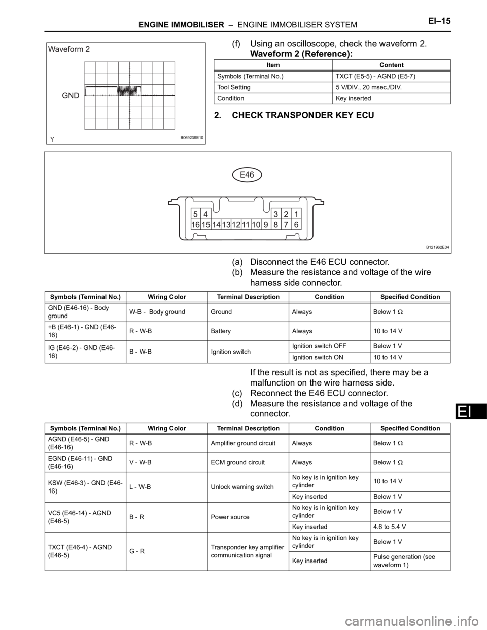
(f) Using an oscilloscope, check the waveform 2.
Waveform 2 (Reference):
2. CHECK TRANSPONDER KEY ECU
(a) Disconnect the E46 ECU connector.
(b) Measure the resistance and voltage of the wire
harness side connector.
If the result is not as specified, there may be a
malfunction on the wire harness side.
(c) Reconnect the E46 ECU connector.
(d) Measure the resistance and voltage of the
connector.
B069239E10
Item Content
Symbols (Terminal No.) TXCT (E5-5) - AGND (E5-7)
Tool Setting 5 V/DIV., 20 msec./DIV.
Condition Key inserted
B121962E04
Symbols (Terminal No.) Wiring Color Terminal Description ConditionSpecified Condition
GND (E46-16) - Body
groundW-B - Body ground Ground Always Below 1
+B (E46-1) - GND (E46-
16)R - W-B Battery Always 10 to 14 V
IG (E46-2) - GND (E46-
16)B - W-B Ignition switchIgnition switch OFF Below 1 V
Ignition switch ON 10 to 14 V
Symbols (Terminal No.) Wiring Color Terminal Description ConditionSpecified Condition
AGND (E46-5) - GND
(E46-16)R - W-B Amplifier ground circuit Always Below 1
EGND (E46-11) - GND
(E46-16)V - W-B ECM ground circuit Always Below 1
KSW (E46-3) - GND (E46-
16)L - W-B Unlock warning switchNo key is in ignition key
cylinder10 to 14 V
Key inserted Below 1 V
VC5 (E46-14) - AGND
(E46-5)B - R Power sourceNo key is in ignition key
cylinderBelow 1 V
Key inserted 4.6 to 5.4 V
TXCT (E46-4) - AGND
(E46-5)G - RTransponder key amplifier
communication signalNo key is in ignition key
cylinderBelow 1 V
Key insertedPulse generation (see
waveform 1)
Page 1787 of 2000
EI–16ENGINE IMMOBILISER – ENGINE IMMOBILISER SYSTEM
EI
If the result is not as specified, there may be a
malfunction in the ECU.
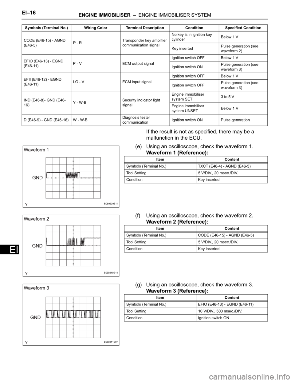
(e) Using an oscilloscope, check the waveform 1.
Waveform 1 (Reference):
(f) Using an oscilloscope, check the waveform 2.
Waveform 2 (Reference):
(g) Using an oscilloscope, check the waveform 3.
Waveform 3 (Reference):
CODE (E46-15) - AGND
(E46-5)P - RTransponder key amplifier
communication signalNo key is in ignition key
cylinderBelow 1 V
Key insertedPulse generation (see
waveform 2)
EFIO (E46-13) - EGND
(E46-11)P - V ECM output signalIgnition switch OFF Below 1 V
Ignition switch ONPulse generation (see
waveform 3)
EFII (E46-12) - EGND
(E46-11)LG - V ECM input signalIgnition switch OFF Below 1 V
Ignition switch OFFPulse generation (see
waveform 3)
IND (E46-8)- GND (E46-
16)Y - W-BSecurity indicator light
signalEngine immobiliser
system SET3 to 5 V
Engine immobiliser
system UNSETBelow 1 V
D (E46-9) - GND (E46-16) W - W-BDiagnosis tester
communicationIgnition switch ON Pulse generation Symbols (Terminal No.) Wiring Color Terminal Description ConditionSpecified Condition
B069239E11
Item Content
Symbols (Terminal No.) TXCT (E46-4) - AGND (E46-5)
Tool Setting 5 V/DIV., 20 msec./DIV.
Condition Key inserted
B069240E14
Item Content
Symbols (Terminal No.) CODE (E46-15) - AGND (E46-5)
Tool Setting 5 V/DIV., 20 msec./DIV.
Condition Key inserted
B069241E07
Item Content
Symbols (Terminal No.) EFIO (E46-13) - EGND (E46-11)
Tool Setting 10 V/DIV., 500 msec./DIV.
Condition Ignition switch ON
Page 1788 of 2000
ENGINE IMMOBILISER – ENGINE IMMOBILISER SYSTEMEI–17
EI
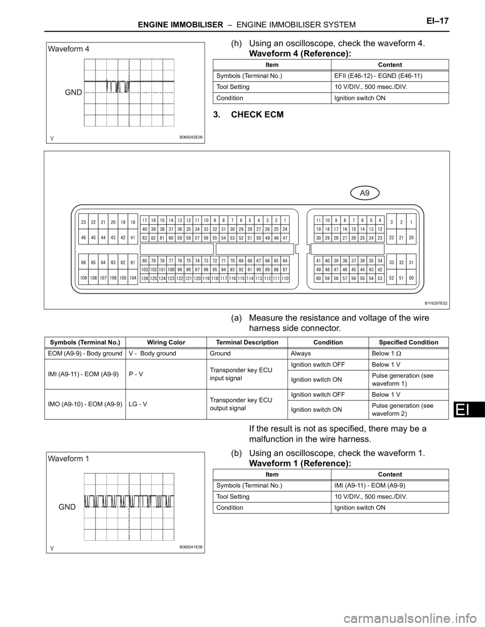
(h) Using an oscilloscope, check the waveform 4.
Waveform 4 (Reference):
3. CHECK ECM
(a) Measure the resistance and voltage of the wire
harness side connector.
If the result is not as specified, there may be a
malfunction in the wire harness.
(b) Using an oscilloscope, check the waveform 1.
Waveform 1 (Reference):
B069242E09
Item Content
Symbols (Terminal No.) EFII (E46-12) - EGND (E46-11)
Tool Setting 10 V/DIV., 500 msec./DIV.
Condition Ignition switch ON
B116297E02
Symbols (Terminal No.) Wiring Color Terminal Description ConditionSpecified Condition
EOM (A9-9) - Body ground V - Body ground Ground Always Below 1
IMI (A9-11) - EOM (A9-9) P - VTransponder key ECU
input signalIgnition switch OFF Below 1 V
Ignition switch ONPulse generation (see
waveform 1)
IMO (A9-10) - EOM (A9-9) LG - VTransponder key ECU
output signalIgnition switch OFF Below 1 V
Ignition switch ONPulse generation (see
waveform 2)
B069241E08
Item Content
Symbols (Terminal No.) IMI (A9-11) - EOM (A9-9)
Tool Setting 10 V/DIV., 500 msec./DIV.
Condition Ignition switch ON
Page 1795 of 2000
EI–24ENGINE IMMOBILISER – ENGINE IMMOBILISER SYSTEM
EI
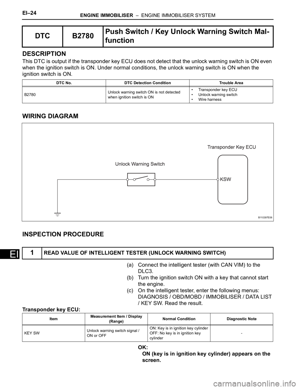
DESCRIPTION
This DTC is output if the transponder key ECU does not detect that the unlock warning switch is ON even
when the ignition switch is ON. Under normal conditions, the unlock warning switch is ON when the
ignition switch is ON.
WIRING DIAGRAM
INSPECTION PROCEDURE
(a) Connect the intelligent tester (with CAN VIM) to the
DLC3.
(b) Turn the ignition switch ON with a key that cannot start
the engine.
(c) On the intelligent tester, enter the following menus:
DIAGNOSIS / OBD/MOBD / IMMOBILISER / DATA LIST
/ KEY SW. Read the result.
Transponder key ECU:
OK:
ON (key is in ignition key cylinder) appears on the
screen.
DTC B2780Push Switch / Key Unlock Warning Switch Mal-
function
DTC No. DTC Detection Condition Trouble Area
B2780Unlock warning switch ON is not detected
when ignition switch is ON• Transponder key ECU
• Unlock warning switch
• Wire harness
1READ VALUE OF INTELLIGENT TESTER (UNLOCK WARNING SWITCH)
B110397E06
ItemMeasurement Item / Display
(Range)Normal Condition Diagnostic Note
KEY SWUnlock warning switch signal /
ON or OFFON: Key is in ignition key cylinder
OFF: No key is in ignition key
cylinder-
Page 1798 of 2000
ENGINE IMMOBILISER – ENGINE IMMOBILISER SYSTEMEI–27
EI
DESCRIPTION
The transponder key coil receives key code signals from the transponder chip in the key grip. The coil
built into the transponder key amplifier amplifies the key code signals and outputs the signal to the
transponder key ECU.
WIRING DIAGRAM
INSPECTION PROCEDURE
(a) Connect the intelligent tester (with CAN VIM) to the
DLC3.
DTC B2784 Antenna Coil Open / Short
DTC No. DTC Detection Condition Trouble Area
B2784 When transponder key coil is open or short• Transponder key ECU
• Transponder key amplifier
• Wire harness
1READ VALUE OF INTELLIGENT TESTER (TRANSPONDER KEY COIL)
B121682E05