Page 14 of 455

14
The vehicle runs in combination with
the gasoline and electric power. Pay
special attention to the following items.
Be careful of high voltage and high
temperature.
Your vehicle is equipped with the orange
colored cables connected to the hybrid
battery (about 200 V) and to other compo-
nents that are all high voltage.
CAUTION
Do not touch or come in contact with
orange cables or battery terminals.
Electric shock may cause serious in-
jury or death. Read all caution labels.
An electric motor, coolant radiator and
some other parts reach high temperature
while driving. Caution labels are applied to
these parts. Carefully observe the instruc-
tions on these caution labels.
CAUTION
Never remove or disassemble any
high voltage part, high voltage cables
(orange color) and their connectors.
It may cause death or serious injury.
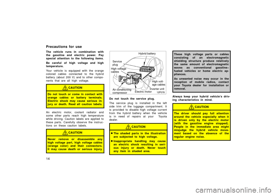
12p078
Inverter unit
Hybrid battery
Service
plug
High volt-
age cables
Air conditioning
compressor
High voltage
cables
Electric motor
Do not touch the service plug.
The service plug is installed in the left
side trim of the luggage compartment. It
is provided to disable high voltage current
from the hybrid battery when the vehicle
is in need of repairs at your Toyota
dealer.
CAUTION
�The shaded parts in the illustration
are subjected to high voltage.
�Inappropriate handling may cause
an electric shock resulting in seri-
ous injury or death. Never touch
any item in shaded area.
These high voltage parts or cables
consisting of an electromagnetic
shielding structure produce relatively
the same amount of electromagnetic
waves as conventional gasoline�
fueled vehicles or home electric ap-
pliances.
As unwanted noise may occur in the
reception of mobile radios, contact
your Toyota dealer for installation or
removal.
Always keep your hybrid vehicle’s driv-
ing characteristics in mind.
CAUTION
The driver should pay full attention
around the vehicle especially when it
is driven only by the electric motor
(with the gasoline engine stopped).
People in the immediate area might
misjudge the hybrid vehicle move-
ment based on the absence of the
regular engine noise.
Precautions for use
Page 160 of 455
160
1. Multi−information display*
(See page 163 for details.)
2. “DISPLAY” button The display adjustment screen is
shown.
(See page 237 for details.)
3. “INFO” button The information menu screen is shown.
(See page 166 for details.)
4. “CLIMATE” button The air conditioning operation screen is
shown.
(See page 286 for details.)
5. “AUDIO” button The audio operation screen is shown.
(See page 242 for details.)
6. “INFO” button (on the steering pad) The trip information screen is shown.
(See page 168 for details.)
7. Speech command button (on the steer- ing pad)
(See page 235 for details.)
8. Telephone button (on the steering pad) (See page 171 for details.)
*: In this manual, English version screens are shown as an example.
Reference
�Ty p e 1
27p163b
Page 161 of 455
161
1. Multi−information display*
(See page 163 for details.)
2. “DISPLAY” button The display adjustment screen is
shown.
(See page 237 for details.)
3. “INFO” button The information menu screen is shown.
(See page 166 for details.)
4. “CLIMATE” button The air conditioning operation screen is
shown.
(See page 286 for details.)
5. “AUDIO” button The audio operation screen is shown.
(See page 242 for details.)
6. “INFO” button (on the steering pad) The trip information screen is shown.
(See page 168 for details.)
7. Speech command button (on the steer- ing pad)
(See page 184 for details.)
8. Telephone button (on the steering pad) (See page 171 for details.)
*: In this manual, English version screens are shown as an example.
�
Ty p e 2
27p162b
Page 162 of 455
162
1. Multi−information display*
(See page 163 for details.)
2. “DISPLAY” button The display adjustment screen is
shown.
(See page 237 for details.)
3. “INFO” button The information menu screen is shown.
(See page 166 for details.)
4. “CLIMATE” button The air conditioning operation screen is
shown.
(See page 286 for details.)
5. “AUDIO” button The audio operation screen is shown.
(See page 242 for details.)
*: In this manual, English version screens are shown as an example.
�
Ty p e 3
Page 173 of 455

173
The other party’s voice outputs from the
driver ’s speaker. When the received calls
or received voice outputs, the audio from
the audio system will be muted.
INFORMATION
�Talk alternately with the other party
on the phone. If you talk at the
same time, the voice may not reach
each other. (It is not a malfunc-
tion.)
�Keep the volume of receiving voice
down. Otherwise, echo is coming
up. When you talk on the phone,
speak clearly towards the micro-
phone.
�In the following situations, your
voice may not reach the other party.� Driving on unpaved road. (Mak-
ing a traffic noise.)
� Driving at the high speed.
� The window is open.
� Turning the air conditioning vents
towards the microphone.
� The sound of the air conditioning
fan is loud.
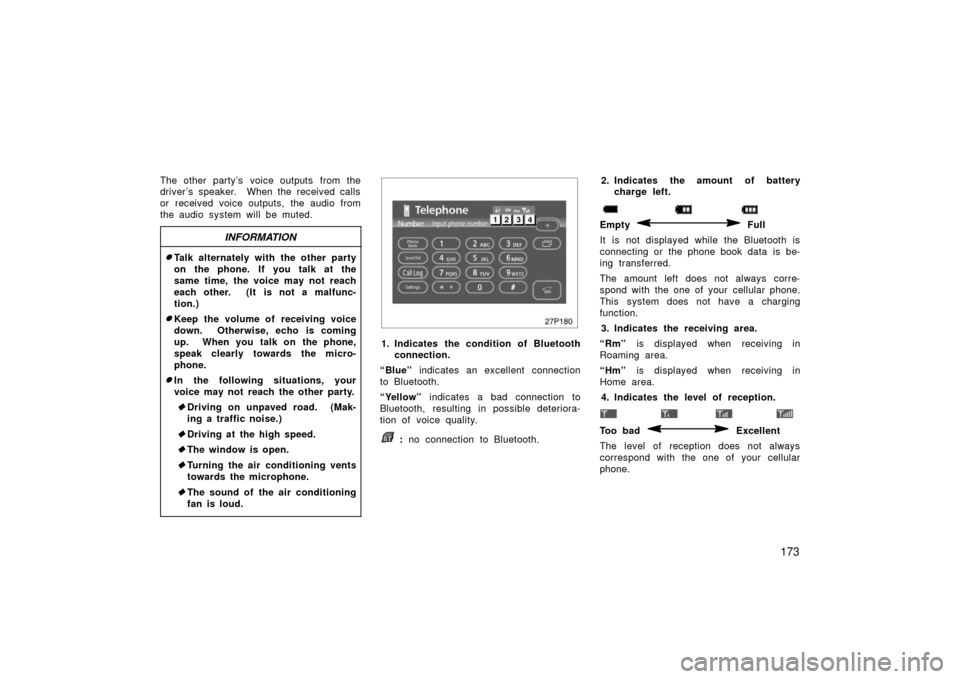
27p180
1. Indicates the condition of Bluetooth
connection.
“Blue” indicates an excellent connection
to Bluetooth.
“Yellow” indicates a bad connection to
Bluetooth, resulting in possible deteriora-
tion of voice quality.
: no connection to Bluetooth. 2. Indicates the amount of battery
charge left.
Empty Full
It is not displayed while the Bluetooth is
connecting or the phone book data is be-
ing transferred.
The amount left does not always corre-
spond with the one of your cellular phone.
This system does not have a charging
function. 3. Indicates the receiving area.
“Rm” is displayed when receiving in
Roaming area.
“Hm” is displayed when receiving in
Home area.
4. Indicates the level of reception.
Too bad Excellent
The level of reception does not always
correspond with the one of your cellular
phone.
Page 279 of 455

279
Here are some common reception prob-
lems that probably do not indicate a prob-
lem with your radio:
FM
Fading and drifting stations—Generally, the
effective range of FM is about 40 km (25
miles). Once outside this range, you may
notice fading and drifting, which increase
with the distance from the radio transmit-
ter. They are often accompanied by distor-
tion.
Multi−path—FM signals are reflective,
making it possible for two signals to reach
your antenna at the same time. If this
happens, the signals will cancel each oth-
er out, causing a momentary flutter or
loss of reception.
Static and fluttering—These occur when
signals are blocked by buildings, trees, or
other large objects. Increasing the bass
level may reduce static and fluttering.
Station swapping—If the FM signal you
are listening to is interrupted or weak-
ened, and there is another strong station
nearby on the FM band, your radio may
tune in the second station until the origi-
nal signal can be picked up again. AM
Fading—AM broadcasts are reflected by
the upper atmosphere—especially at night.
These reflected signals can interfere with
those received directly from the radio sta-
tion, causing the radio station to sound
alternately strong and weak.
Station interference—When a reflected sig-
nal and a signal received directly from a
radio station are very nearly the same
frequency, they can interfere with each
other, making it difficult to hear the broad-
cast.
Static—AM is easily affected by external
sources of electrical noise, such as high
tension power lines, lightening, or electri-
cal motors. This results in static.
CARING FOR YOUR COMPACT DISC
PLAYER AND DISCS
�The player is intended for use with
12cm (4.7 in.) discs only.
�Extremely high temperatures can keep
your compact disc player from working.
On hot days, use the air conditioning
to cool the vehicle interior before you
listen to a disc.
�Bumpy roads or other vibrations may
make your compact disc player skip.
�If moisture gets into your compact disc
player, you may not hear any sound
even though your compact disc player
appears to be working. Remove the
disc from the player and wait until it
dries.
CAUTION
Compact disc players use an invisible
laser beam which could cause hazard-
ous radiation exposure if directed
outside the unit. Be sure to operate
the player correctly.
Page 285 of 455
285
OPERATION OF INSTRUMENTS AND
CONTROLS
Air conditioning system
Controls286
. . . . . . . . . . . . . . . . . . . . . . . . . . . . . . . . . . . . .\
. . . . . . . . . . . . . .
Climate remote control 297
. . . . . . . . . . . . . . . . . . . . . . . . . . . . . . . . . . . . \
. .
Instrument panel ventss 297
. . . . . . . . . . . . . . . . . . . . . . . . . . . . . . . . . . . . \
Air conditioning filter 298
. . . . . . . . . . . . . . . . . . . . . . . . . . . . . . . . . . . . \
. . . .
SECTION 2– 9
Page 286 of 455
286
1. Passenger compartment temperaturedisplay
2. Outside temperature display
3. Temperature control switch
4. Air flow control switch
5. Fan speed control switch
6. Automatic control switch
7. Air intake control switch
8. Rear window and outside rear view mirror defogger switch (See page 118
for details.)
9. Windshield air flow switch
10. Air conditioning on −off switch
11. Air conditioning operation screen dis- play button
12. OFF switch
In this manual, English version screens
are shown as an example.
Controls
� Ty p e 1
27p165a