Page 168 of 470

158
“START”—Starter motor on. The key
will return to the “ON” position when
released.
For starting tips, see page 355 in Section
3.
“ON”—Engine on and all ac")
’06 4Runner_U (L/O 0508)
158
“START”—Starter motor on. The key
will return to the “ON” position when
released.
For starting tips, see page 355 in Section
3.
“ON”—Engine on and all accessories
on.
This is the normal driving position.
“ACC”—Accessories such as the radio
operate, but the engine is off.
If you leave the key in the “ACC” or
“LOCK” position and open the driver’s
door, a buzzer will remind you to remove
the key. “LOCK”—Engine is off and the steering
wheel is locked. The key can be re-
moved only at this position.
You must push in the key to turn it from
“ACC” to the “LOCK” position. The selec-
tor lever must be in the “P” position be-
fore pushing the key.
Once you remove the key, the engine im-
mobilizer system is automatically set. (See
“Engine immobilizer system” on page 14
in Section 1−
2.)
When starting the engine, the key may
seem stuck at the “LOCK” position. To
free it, first be sure the key is pushed all
the way in, and then rock the steering
wheel slightly while turning the key gently.
Approximately five hours after the engine
is turned off, you may hear sound coming
from underneath the luggage compartment
for several minutes. This is normal opera-
tion and does not indicate a malfunction.
(See “Leak detection pump” on page x.)
It is not a malfunction if the needles on
all meters and gauges move slightly when
the key is turned to the “ACC”, “ON” or
“START” position.
NOTICE
Do not leave the key in the “ON”
position if the engine is not running.
The battery will discharge and the
ignition could be damaged.
Ignition switch
Page 202 of 470

192
If the warning light blinks:
The tire pressure warning system may
be malfunctioning. Contact your Toyota
dealer.
SYSTEM MALFUNCTION
The tire pressure warning system does")
’06 4Runner_U (L/O 0508)
192
If the warning light blinks:
The tire pressure warning system may
be malfunctioning. Contact your Toyota
dealer.
SYSTEM MALFUNCTION
The tire pressure warning system does
not function properly under certain cir-
cumstances. In the following cases, the
low tire pressure warning light may not
come on even if the tire inflation pres-
sure is low, or it may come on when
the tire inflation pressure is actually
normal.
�Electric devices or facilities using simi-
lar radio wave frequencies are nearby.
�A radio set to similar frequencies is in
use.
�A lot of snow or ice covers the ve-
hicle, in particular, around the wheels
or wheel housings.
�The tires are not equipped with an air
pressure sensor.
�Snow tires or tire chains are used.
�Non−genuine Toyota wheels are used.
�The sensor battery is expired.
�Radio waves from the air pressure sen-
sor installed on the spare tire cannot
be received.
CAUTION
�The use of non�genuine wheels will
cause the air pressure sensors to
transmit the electronic code in dif-
ferent manner, resulting in the sys-
tem failure.
�The use of different type of tires
with genuine wheels may also
cause the malfunction of the sys-
tem.
CAUTION
Each tire, including the spare (if pro-
vided), should be checked monthly
when cold and inflated to the inflation
pressure recommended by the vehicle
manufacturer on the vehicle placard
or tire inflation pressure label (tire
and load information label). (If your
vehicle has tires of a different size
than the size indicated on the vehicle
placard or tire inflation pressure label
(tire and load information label), you
should determine the proper tire infla-
tion pressure for those tires.)
Page 243 of 470
’06 4Runner_U (L/O 0508)
233
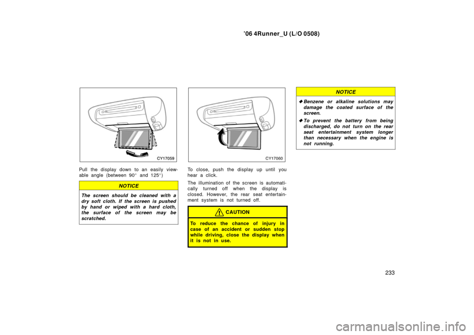
Pull the display down to an easily view-
able angle (between 90 � and 125 �)
NOTICE
The screen should be cleaned with a
dry soft cloth. If the screen is pushed
by hand or wiped with a hard cloth,
the surface of the screen may be
scratched.
To close, push the display up until you
hear a click.
The illumination of the screen is automati-
cally turned off when the display is
closed. However, the rear seat entertain-
ment system is not turned off.
CAUTION
To reduce the chance of injury in
case of an accident or sudden stop
while driving, close the display when
it is not in use.
NOTICE
� Benzene or alkaline solutions may
damage the coated surface of the
screen .
� To prevent the battery from being
discharged, do not turn on the rear
seat entertainment system longer
than necessary when the engine is
not running.
Page 244 of 470
’06 4Runner_U (L/O 0508)
234
The rear seat entertainment system can
be operated with the rear seat entertain-
ment system controller and buttons on the
DVD player unit. The system cannot be
operated by touching the switches on the
screen directly.
CAUTION
Do not disassemble or modify the
controller. It may cause an accident,
fire or electric shock.
NOTICE
Keep the controller away from direct
sunlight, high heat and high humidity.
These conditions could cause the
case to deform or the battery to ex-
plode or leak.
BEFORE USING THE CONTROLLER
(for new vehicle owners)
A battery is already set in the control-
ler with an insulating sheet, which pre-
vents the battery from being dis-
charged. Before using the controller,
remove the insulating sheet according
to the following procedure.
1. Remove the cover of the controller
as shown.
—Rear seat entertainment
system controller
Page 248 of 470

238
9. “” button
This button stops a screen when the
DVD player is operated.
10. “SET UP” button
This button indicates the initial set up
screen when the DVD player")
’06 4Runner_U (L/O 0508)
238
9. “” button
This button stops a screen when the
DVD player is operated.
10. “SET UP” button
This button indicates the initial set up
screen when the DVD player is oper-
ated.
11. “MENU” button This button indicates the menu screen
for DVD video when the DVD player is
operated.
12. “AUDIO” button This button indicates the changing au-
dio screen when the DVD player is
operated.
13. “SUB TITLE” button
This button indicates the changing sub-
title screen when the DVD player is
operated.
14. “DISPLAY” button
This button adjusts the color, tone,
contrast and brightness of the screen.
15. “SIZE” button
This button changes the display mode
when the DVD player is operated. 16. “ANGLE” button
This button selects the angle of the
screen when the DVD player is oper-
ated.
17. “SEARCH” button
This button indicates the title search
screen when the DVD player is oper-
ated.
18. “TOP MENU” button This button indicates the title selection
screen for DVD video when the DVD
player is operated.
19. “
” button
This button reverse a screen when the
DVD player is operated.
20. “ �
” button
This button plays or pauses a screen
when the DVD player is operated.
21. “TRACK/CHAPTER
” button
This button selects track/chapter.
22. “TRACK/CHAPTER
” button
This button selects track/chapter.
23. “OPTION” button This button indicates the control
switches on the screen when the DVD
player is operated. REPLACING CONTROLLER BATTERY
For replacement, use 3 AA batteries.
CAUTION
Special care should be taken to pre-
vent small children from swallowing
the removed transmitter battery or
components.
NOTICE
�
When replacing the battery, be care-
ful not to lose the components.
� Replace only with the same or
equivalent type of battery recom-
mended by a Toyota dealer.
� Dispose of used batteries according
to local regulations.
Page 249 of 470
’06 4Runner_U (L/O 0508)
239
Replace the battery according to the fol-
lowing procedure:
1. Remove the cover of the controller as shown.2. Remove the discharged batteries andput in the new batteries as shown.
Install the cover.
NOTICE
�Be sure that the positive side and
negative side of the controller bat-
tery should be faced correctly.
� Do not replace the battery with wet
hands. Water may cause rust.
� Do not touch or move any compo-
nents inside of the controller, or it
may interfere with proper operation.
� Be careful not to bend the electrode
of the controller battery insertion.
� Close the battery case securely.
After replacing the battery, check that the
controller operates properly. If the control-
ler still does not operate properly, contact
your Toyota dealer.
Page 280 of 470

270
NOTICE
�To prevent the battery from being
discharged, do not use the power
outlet longer than necessary when
the engine is not running.
� Close the power outlet lid when")
’06 4Runner_U (L/O 0508)
270
NOTICE
�To prevent the battery from being
discharged, do not use the power
outlet longer than necessary when
the engine is not running.
� Close the power outlet lid when the
power outlet is not in use. Inserting
a foreign object other than the ap-
propriate plug that fits the outlet
may cause electrical failure or short
circuit.
The power outlet is not designed for
the following electric appliances even if
their power consumption is under 115
VAC/100W. These appliances may not
operate properly.
�Appliances with high initial peak watt-
age: cathode− ray tube type televisions,
compressor −driven refrigerators, electric
pumps, electric tools, etc.
�Measuring devices which process pre-
cise data: medical equipment, measur-
ing instruments, etc.
�Other appliances requiring an extremely
stable power supply: microcomputer −
controlled electric blankets, touch sen-
sor lamps, etc.
Certain electrical appliances may cause
radio noise.NOTICE
To ensure correct audio/video system
operation:
� Be careful not to spill beverages
over the system.
� Do not put anything other than a
compact disc into the slot.
� Do not put anything other than a
DVD video, video CD, dts�CD or au-
dio CD into the DVD player.
� The use of a cellular phone inside
or near the vehicle may cause a
noise from the speakers of the sys-
tem which you are listening to.
However, this does not indicate a
malfunction.
RADIO RECEPTION
Usually, a problem with radio reception
does not mean there is a problem with
your radio—it is just the normal result of
conditions outside the vehicle.
Audio/video system operating
hints
Page 308 of 470

298
The compass indicates the direction
that the vehicle is heading. In the
above case, it shows that the vehicle is
heading north.
Displays
Directions
N
NE E
SE
S
SW W
NWNo")
’06 4Runner_U (L/O 0508)
298
The compass indicates the direction
that the vehicle is heading. In the
above case, it shows that the vehicle is
heading north.
Displays
Directions
N
NE E
SE
S
SW W
NWNorth
Northeast East
Southeast
South
Southwest West
Northwest
The compass may not show the correct
direction in the following conditions:
�The vehicle is stopped immediately af-
ter turning.
�The compass does not adjust while the
vehicle is stopped.
�The ignition switch is turned off imme-
diately after turning.
�The vehicle is on an inclined surface.
�The vehicle is in a place where the
earth’s magnetic field is subject to in-
terference by artificial magnetic fields
(underground parking, under a steel
tower, between buildings, roof parking,
near a crossing, near a large vehicle,
etc.).
�The vehicle is magnetized. (There is a
magnet or a metal object on or near
the inside rear view mirror.)
�The battery has been disconnected.
If your vehicle is out of the set zone,
refer to “CALIBRATING THE COMPASS”
below to set the zone number.
If the deviation is small, the compass
works to calibrate the direction automati-
cally while the vehicle is in motion.
For additional precision or for complete
calibrating, see “CALIBRATING THE
COMPASS” below.
Compass sensor
The compass sensor is on the wind-
shield.
NOTICE
Do not put magnets or a metal object
on or near the inside rear view mirror
of the vehicle. Doing this may cause
malfunction of the compass sensor.

234
The rear seat entertainment system can
be operated with the rear seat entertain-
ment system controller and buttons on the
DVD player unit. The system cannot be
operate")

239
Replace the battery according to the fol-
lowing procedure:
1. Remove the cover of the controller as shown.2. Remove the discharged batteries andput in the new batteries")