Page 1253 of 1556
Downloaded from www.Manualslib.com manuals search engine Wiring Systems: 9A-86
19G041
B
BG06
11
J/C
G309
A
A
J/C
G306
BLK
14
BLK
"F-1"
YELBLK
A/B
SDM
Switch
Auto
unit"D-6"
Model control
switch
"E-1""E-2"
A/T shift
lever
"D-4"
Switch
"D-3"
Audio
"G-1"
Y
G0434G05
WHT
W
14
BLK/YEL
BLK/YEL
BY
C
C
J/C
G306
14
BLK/YEL
C
C
J/C
G308
YEL
BLK
BY
"A-2" Generator
10
WHT/BLU
WB
5
YEL
Y
GRY
16G04
G
"G-2" Multi
information
display
BCM
Auto
unit
"E-2"
Switch
"D-6"
I6RW0C910958-01
Page 1282 of 1556

Downloaded from www.Manualslib.com manuals search engine 9A-115 Wiring Systems:
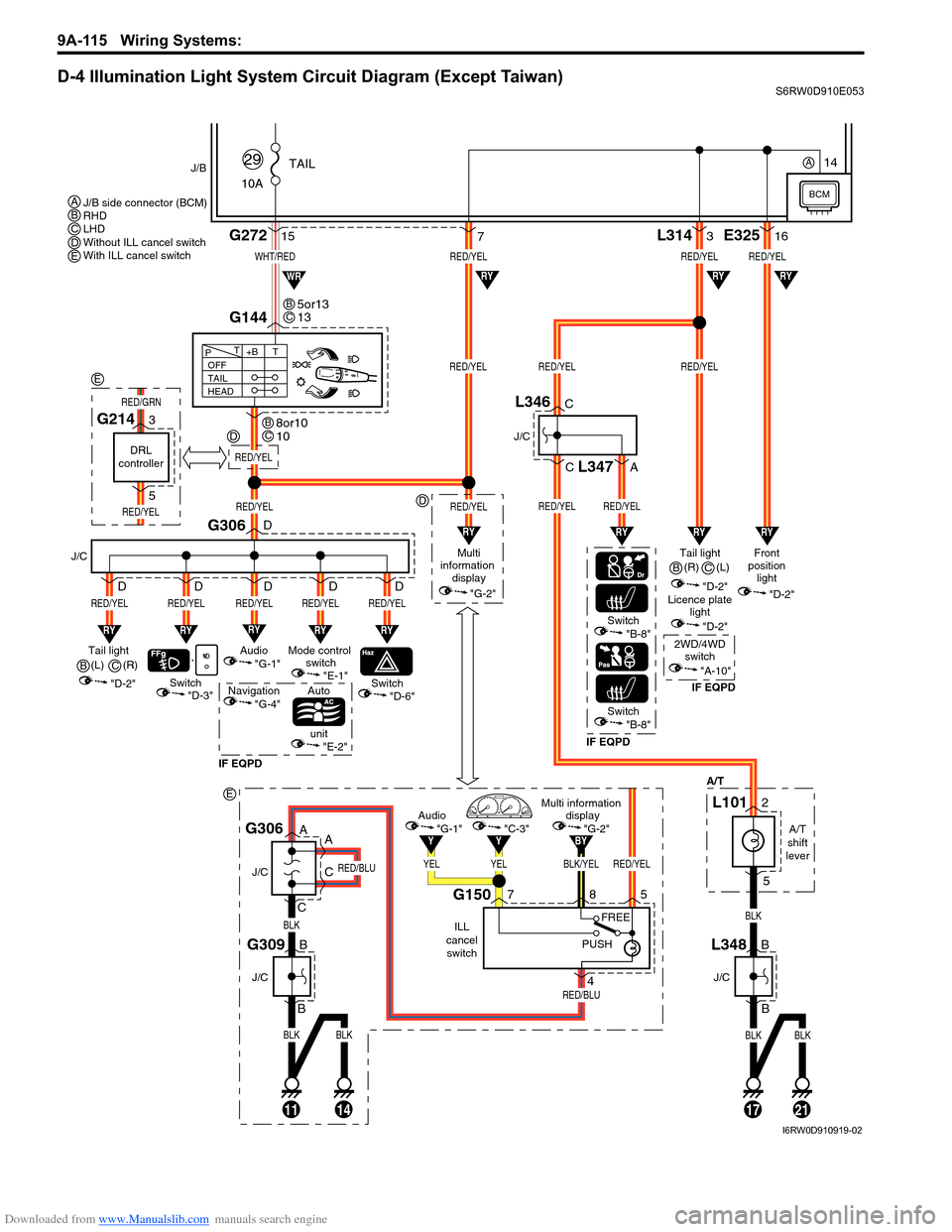
D-4 Illumination Light System Circuit Diagram (Except Taiwan)S6RW0D910E053
BLKBLK
BLK
RED/BLU
RED/BLU
11
J/C
J/C
B
B
14
G309
A
A
C
CG306
BLK/YELRED/YEL
BY
YELYEL
YY
Multi information
display
"G-2"Audio
"G-1""C-3"
ILL
cancel
switch
G150758
4
PUSHFREE
WHT/RED
10ATAIL
29J/B
15G272
G144
1721
RED/YELRED/YELRED/YEL
RED/YELRED/YEL
L3143
BLKBLK
BLK
"D-3"
A/T
RY
Switch
J/C
G306
RED/YEL
RY
RED/YEL
Switch
Auto
unit
IF EQPDIF EQPDIF EQPD
RY
RED/YEL
Mode control
switch
"E-1"Tail light
(L)
"D-2"
"E-2"
"D-6"Switch"B-8"
Switch"B-8"
OFF
TAIL
HEAD+BT T
P
7
RY
RED/YEL
Audio
"G-1"
Navigation
"G-4"
D
D
D D D
RY
RED/YEL
D
RED/YEL
Multi
information
display
"G-2"
RED/YEL
RYRYRY
RYRYWR
Tail light
"D-2"Front
position
light
"D-2"
Licence plate
light
"D-2"
2WD/4WD
switch
"A-10"
RED/YELRED/YEL
RED/YEL
E32516
RY
RY
J/C
B
BL348
J/C
C
C
A
L346
L347
A/T
shift
lever
L1012
5
5or13
13BC
8or10
10BC
J/B side connector (BCM)
RHD
LHD
Without ILL cancel switch
With ILL cancel switch ABCDE
B(R)
C
(R)
B(L)
C
BCM
14A
RED/YEL
D
D
E
DRL
controller
G2143
5
RED/YEL
RED/GRN
E
I6RW0D910919-02
Page 1283 of 1556
Downloaded from www.Manualslib.com manuals search engine Wiring Systems: 9A-116
D-4 Illumination Light System Circuit Diagram (Taiwan)S6RW0D910E025
BLU/WHT
RED/YEL
10ATAIL
36
J/B
12G272
10
G14413
131721
RED/YELRED/YEL
RED/YELRED/YELRED/YEL
L3143
BLKBLK
BLKBLK
"D-3"
A/T
RY
Switch
J/C
G306
RED/YEL
RY
RED/YEL
Switch
Auto
unit
RY
RED/YEL
Mode control
switch
"E-1"Tail light
(R)
"D-2"
"E-2"
"D-6"
OFF
TAIL
HEAD+BT T
P
187
RY
RED/YEL
Audio
"G-1"
D
D
D D D
RY
RED/YEL
D
RED/YEL
Multi
information
display
"G-2"
RED/YEL
RYRY
RYRY
RY
Tail light (L)
"D-2"Front
position
light
"D-2"
Licence plate
light
"D-2"
RED/YEL
RED/YEL
E32516
RY
RY
J/C
B
BL348
J/C
C
CL346
A/T
shift
lever
L1012
5
2 1
3
4
Tail light
relay
11
G05
G0412
BCM
I6RW0C910985-01
Page 1305 of 1556
Downloaded from www.Manualslib.com manuals search engine Wiring Systems: 9A-138
G-1 Audio System Circuit DiagramS6RW0D910E037
G2715
5
4
11
2
12
1 5
156
16
"D-4"RY
WHT/RED
WHT/RED
G2481
G307
J/B
15ADOME
37
J/C
BLU/WHT
BLU/WHTRED/YEL
15AACC2
24
Rear (R)
J/C
Rear (L)
GRY/REDGRYLT GRN/BLKLT GRN
GRY/REDGRYLT GRN/BLKLT GRN
GRY/REDGRYLT GRN/BLKLT GRN
Audio
RED/YEL
92
J146
C
CG308
J/C
B
BG306
J/C
D
D
P
PPL
18
L381
J2175
4L382
J218
J145
G341
L374
G343
L376
1
2
Rear tweeter (R)
GRY/REDGRY
J1511
2
Rear tweeter (L)
LT GRNLT GRN/BLK
J152
BCM
"A-8"
A
B
G343
L376
G341
L374A
B
9
6AB8
5AB6
9AB5
8AB
RHD
LHD AB
I6RW0C910A07-01
Page 1306 of 1556
Downloaded from www.Manualslib.com manuals search engine 9A-139 Wiring Systems:
K12112
102102
2
11
22
11
211
G248
G248
BLK
Tweeter (L)Front (L)
J142J148
Tweeter (R)Front (R)
J141
J147
BLK
YEL
BLK
Audio
G306
J/C
ILL cancel
switch
A
A
C
C
G306
J/C
C
C
Steering switch (Audio control switch)
19G26710 120
BLKGRNWHT/GRN
BLK
BLUPNK
BLUPNK
BLUPNK
BLUBLKBLKBLUPNKPNK
YEL/BLKYEL/RED
YEL/BLKYEL/RED
YEL/BLKYEL/RED
YEL/BLKYEL/BLKYEL/REDYEL/RED
S171
G346S61
Roof audio antenna
Contact
coil
Antenna amplifer
4 313 14
K153
G3481
BLK
BLK
K154
G3541
21
G343
L376
G341
L3742112
BLK/YEL
RED/BLU
RED/BLU
G309
J/C
B
B
141114
RHD
LHD
Without Auto cruise
With Auto cruise
Except Taiwan
Taiwan
Without ILL cancel switch
With ILL cancel switch A
E
G
H
A
B
G341
L374
G343
L376A
B
L379
J215
L380
J216A
B
L380
J216
L379
J215A
B
F
BCDEFGH
4
1CD3
2CD
4
1CD3
2CD
Y
"D-4"
I6RW0D910924-01
Page 1309 of 1556

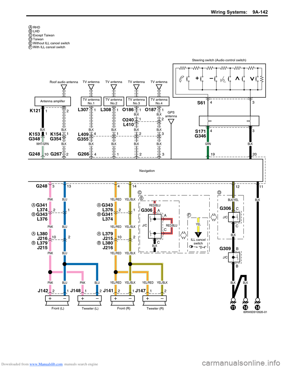
Downloaded from www.Manualslib.com manuals search engine Wiring Systems: 9A-142
K121L30712
102102
2
11
22
11
211
G248
G248
BLK
Tweeter (L)Front (L)
J142J148
Tweeter (R)Front (R)
J141
J147
BLK
BLK
Navigation
G306
J/C
A
A
C
C
G306
J/C
C
C
Steering switch (Audio control switch)
19G26710 220
BLKGRNWHT/GRN
BLK
BLUPNK
BLUPNK
BLUPNK
BLUBLKBLKBLUPNKPNK
YEL/BLKYEL/RED
YEL/BLKYEL/RED
YEL/BLKYEL/RED
YEL/BLKYEL/BLKYEL/REDYEL/RED
S171
G346S61
Roof audio antenna
Antenna amplifer
4 313 14
K153
G3481
BLK
BLK
K154
G35411
G2664
TV antenna
TV antenna
No.1
BLK
BLK
L409
G3554
O240
L4101
21
G343
L376
G341
L3742112
BLK/YEL
RED/BLU
RED/BLU
G309
J/C
B
B
141114
RHD
LHD
Except Taiwan
Taiwan
Without ILL cancel switch
With ILL cancel switch A
C
E
F
A
B
G341
L374
G343
L376A
B
L379
J215
L380
J216A
B
L380
J216
L379
J215A
B
D
BCDEF
43 43
L3081
1
TV antenna
TV antenna
No.2
BLK
BLK1
O1861
2
TV antenna
TV antenna
No.3
BLK
BLK
BLK
2
2
O1871
3
TV antenna
TV antenna
No.4
BLK
BLK
BLK
3
GPS
antenna
YEL
ILL cancel
switch
Y
"D-4"
I6RW0D910926-01
Page 1357 of 1556

Downloaded from www.Manualslib.com manuals search engine Instrumentation / Driver Info. / Horn: 9C-5
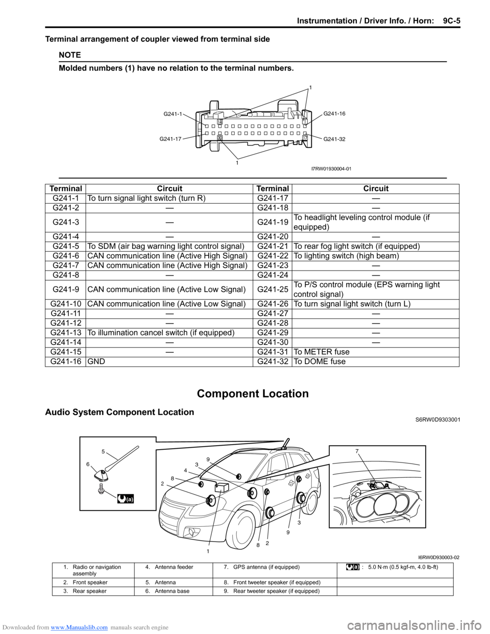
Terminal arrangement of coupler viewed from terminal side
NOTE
Molded numbers (1) have no relation to the terminal numbers.
Component Location
Audio System Component LocationS6RW0D9303001
Terminal Circuit Terminal Circuit
G241-1 To turn signal light switch (turn R) G241-17 —
G241-2 — G241-18 —
G241-3 — G241-19To headlight leveling control module (if
equipped)
G241-4 — G241-20 —
G241-5 To SDM (air bag warning light control signal) G241-21 To rear fog light switch (if equipped)
G241-6 CAN communication line (Active High Signal) G241-22 To lighting switch (high beam)
G241-7 CAN communication line (Active High Signal) G241-23 —
G241-8 — G241-24 —
G241-9 CAN communication line (Active Low Signal) G241-25To P/S control module (EPS warning light
control signal)
G241-10 CAN communication line (Active Low Signal) G241-26 To turn signal light switch (turn L)
G241-11 — G241-27 —
G241-12 — G241-28 —
G241-13 To illumination cancel switch (if equipped) G241-29 —
G241-14 — G241-30 —
G241-15 — G241-31 To METER fuse
G241-16 GND G241-32 To DOME fuse
G241-1G241-16
G241-32 G241-17
11I7RW01930004-01
3
2
3
2
1
4
8
8
9
96
5
(a)
7
I6RW0D930003-02
1. Radio or navigation
assembly4. Antenna feeder 7. GPS antenna (if equipped) : 5.0 N⋅m (0.5 kgf-m, 4.0 lb-ft)
2. Front speaker 5. Antenna 8. Front tweeter speaker (if equipped)
3. Rear speaker 6. Antenna base 9. Rear tweeter speaker (if equipped)
Page 1364 of 1556

Downloaded from www.Manualslib.com manuals search engine 9C-12 Instrumentation / Driver Info. / Horn:
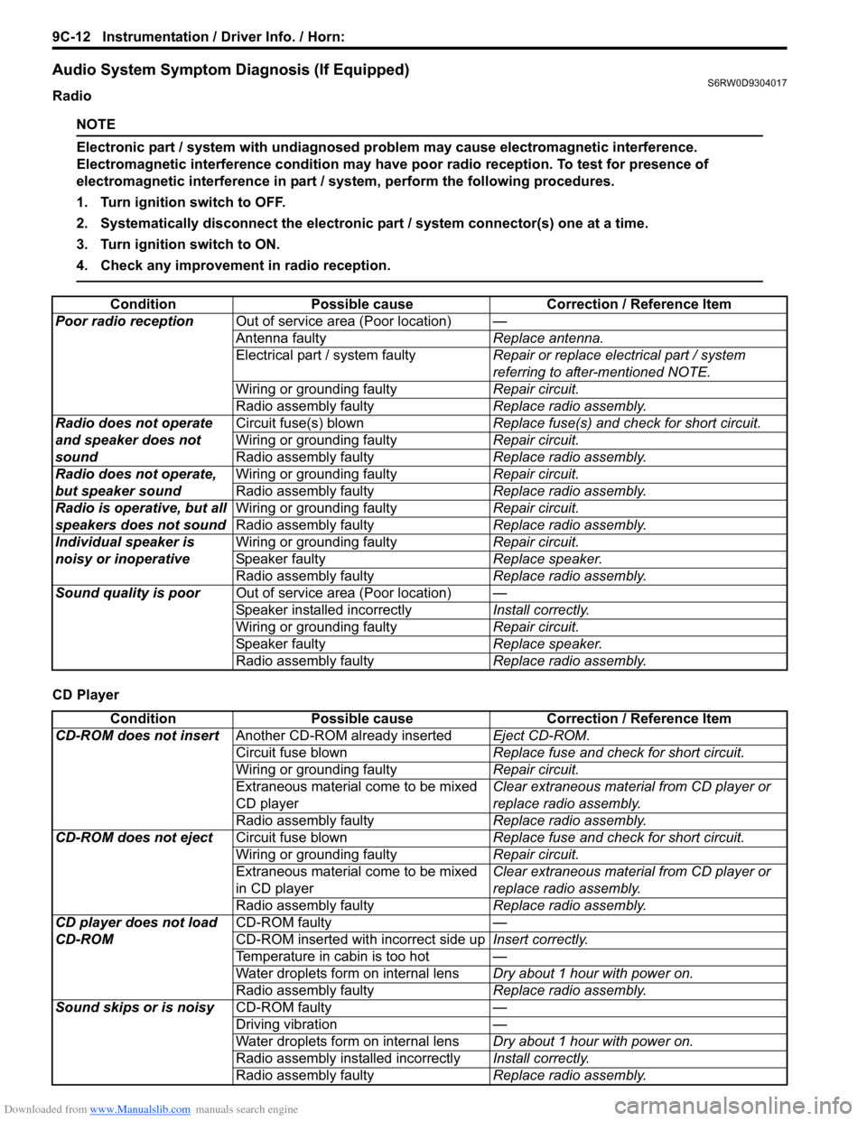
Audio System Symptom Diagnosis (If Equipped)S6RW0D9304017
Radio
NOTE
Electronic part / system with undiagnosed problem may cause electromagnetic interference.
Electromagnetic interference condition may have poor radio reception. To test for presence of
electromagnetic interference in part / system, perform the following procedures.
1. Turn ignition switch to OFF.
2. Systematically disconnect the electronic part / system connector(s) one at a time.
3. Turn ignition switch to ON.
4. Check any improvement in radio reception.
CD PlayerCondition Possible cause Correction / Reference Item
Poor radio receptionOut of service area (Poor location)—
Antenna faultyReplace antenna.
Electrical part / system faultyRepair or replace electrical part / system
referring to after-mentioned NOTE.
Wiring or grounding faultyRepair circuit.
Radio assembly faultyReplace radio assembly.
Radio does not operate
and speaker does not
soundCircuit fuse(s) blownReplace fuse(s) and check for short circuit.
Wiring or grounding faultyRepair circuit.
Radio assembly faultyReplace radio assembly.
Radio does not operate,
but speaker soundWiring or grounding faultyRepair circuit.
Radio assembly faultyReplace radio assembly.
Radio is operative, but all
speakers does not soundWiring or grounding faultyRepair circuit.
Radio assembly faultyReplace radio assembly.
Individual speaker is
noisy or inoperativeWiring or grounding faultyRepair circuit.
Speaker faultyReplace speaker.
Radio assembly faultyReplace radio assembly.
Sound quality is poorOut of service area (Poor location)—
Speaker installed incorrectlyInstall correctly.
Wiring or grounding faultyRepair circuit.
Speaker faultyReplace speaker.
Radio assembly faultyReplace radio assembly.
Condition Possible cause Correction / Reference Item
CD-ROM does not insertAnother CD-ROM already insertedEject CD-ROM.
Circuit fuse blownReplace fuse and check for short circuit.
Wiring or grounding faultyRepair circuit.
Extraneous material come to be mixed
CD playerClear extraneous material from CD player or
replace radio assembly.
Radio assembly faultyReplace radio assembly.
CD-ROM does not ejectCircuit fuse blownReplace fuse and check for short circuit.
Wiring or grounding faultyRepair circuit.
Extraneous material come to be mixed
in CD playerClear extraneous material from CD player or
replace radio assembly.
Radio assembly faultyReplace radio assembly.
CD player does not load
CD-ROMCD-ROM faulty—
CD-ROM inserted with incorrect side upInsert correctly.
Temperature in cabin is too hot—
Water droplets form on internal lensDry about 1 hour with power on.
Radio assembly faultyReplace radio assembly.
Sound skips or is noisyCD-ROM faulty—
Driving vibration—
Water droplets form on internal lensDry about 1 hour with power on.
Radio assembly installed incorrectlyInstall correctly.
Radio assembly faultyReplace radio assembly.