2006 SUZUKI SX4 terminal
[x] Cancel search: terminalPage 1022 of 1556
Downloaded from www.Manualslib.com manuals search engine 7B-82 Air Conditioning System: Automatic Type
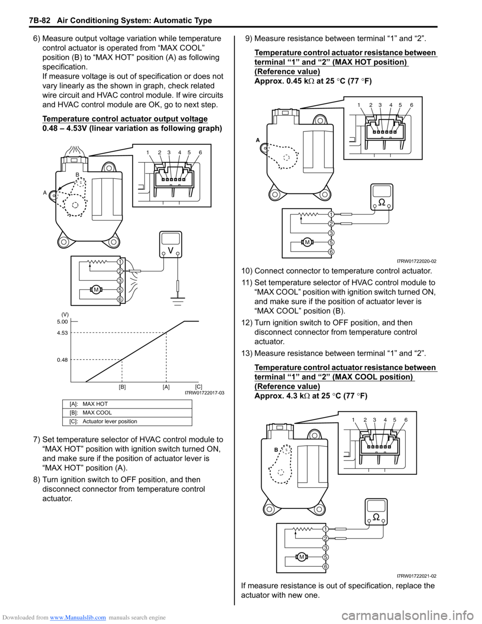
6) Measure output voltage variation while temperature
control actuator is operated from “MAX COOL”
position (B) to “MAX HOT” position (A) as following
specification.
If measure voltage is out of specification or does not
vary linearly as the shown in graph, check related
wire circuit and HVAC control module. If wire circuits
and HVAC control module are OK, go to next step.
Temperature control actuator output voltage
0.48 – 4.53V (linear variation as following graph)
7) Set temperature selector of HVAC control module to
“MAX HOT” position with ignition switch turned ON,
and make sure if the position of actuator lever is
“MAX HOT” position (A).
8) Turn ignition switch to OFF position, and then
disconnect connector from temperature control
actuator.9) Measure resistance between terminal “1” and “2”.
Temperature control actuator resistance between
terminal “1” and “2” (MAX HOT position)
(Reference value)
Approx. 0.45 kΩ at 25 °C (77 °F)
10) Connect connector to temperature control actuator.
11) Set temperature selector of HVAC control module to
“MAX COOL” position with ignition switch turned ON,
and make sure if the position of actuator lever is
“MAX COOL” position (B).
12) Turn ignition switch to OFF position, and then
disconnect connector from temperature control
actuator.
13) Measure resistance between terminal “1” and “2”.
Temperature control actuator resistance between
terminal “1” and “2” (MAX COOL position)
(Reference value)
Approx. 4.3 kΩ at 25 °C (77 °F)
If measure resistance is out of specification, replace the
actuator with new one.[A]: MAX HOT
[B]: MAX COOL
[C]: Actuator lever position
123456
6
M5
3
2
1
AB
4.53
0.48 5.00(V)
[C]
[A] [B]
I7RW01722017-03
123456
6
M5
3
2
1
A
I7RW01722020-02
123456
6
M5
3
2
1
B
I7RW01722021-02
Page 1023 of 1556
Downloaded from www.Manualslib.com manuals search engine Air Conditioning System: Automatic Type 7B-83
Air Flow Control Actuator Removal and
Installation
S6RW0D7226006
Removal
1) Disconnect negative cable at battery.
2) Remove steering column hole cover from instrument
panel.
3) Remove driver side foot duct from HVAC unit.
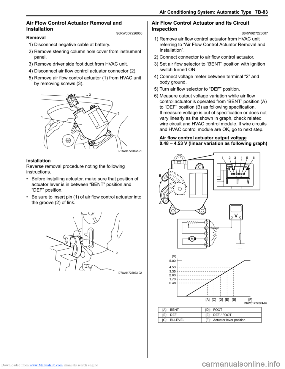
4) Disconnect air flow control actuator connector (2).
5) Remove air flow control actuator (1) from HVAC unit
by removing screws (3).
Installation
Reverse removal procedure noting the following
instructions.
• Before installing actuator, make sure that position of
actuator lever is in between “BENT” position and
“DEF” position.
• Be sure to insert pin (1) of air flow control actuator into
the groove (2) of link.
Air Flow Control Actuator and Its Circuit
Inspection
S6RW0D7226007
1) Remove air flow control actuator from HVAC unit
referring to “Air Flow Control Actuator Removal and
Installation”.
2) Connect connector to air flow control actuator.
3) Set air flow selector to “BENT” position with ignition
switch turned ON.
4) Connect voltage meter between terminal “2” and
body ground.
5) Turn air flow selector to “DEF” position.
6) Measure output voltage variation while air flow
control actuator is operated from “BENT” position (A)
to “DEF” position (B) as following specification.
If measure voltage is out of specification or does not
vary linearly as the shown in graph, check related
wire circuit and HVAC control module. If wire circuits
and HVAC control module are OK, go to next step.
Air flow control actuator output voltage
0.48 – 4.53 V (linear variation as following graph)
13
2
I7RW01722022-01
1
2
I7RW01722023-02
[A]: BENT [D]: FOOT
[B]: DEF [E]: DEF / FOOT
[C]: BI-LEVEL [F]: Actuator lever position
123456
6
M5
3
2
1 A
B
(V)
4.53
3.35
2.60
1.78
0.48
[A][B]
[C] [D] [E][F]5.00
I7RW01722024-02
Page 1024 of 1556
Downloaded from www.Manualslib.com manuals search engine 7B-84 Air Conditioning System: Automatic Type
7) Set air flow selector of HVAC control module to
“DEF” position with ignition switch turned ON, and
make sure if the position of actuator lever is “DEF”
position (A).
8) Turn ignition switch to OFF position, and then
disconnect connector from air flow control actuator.
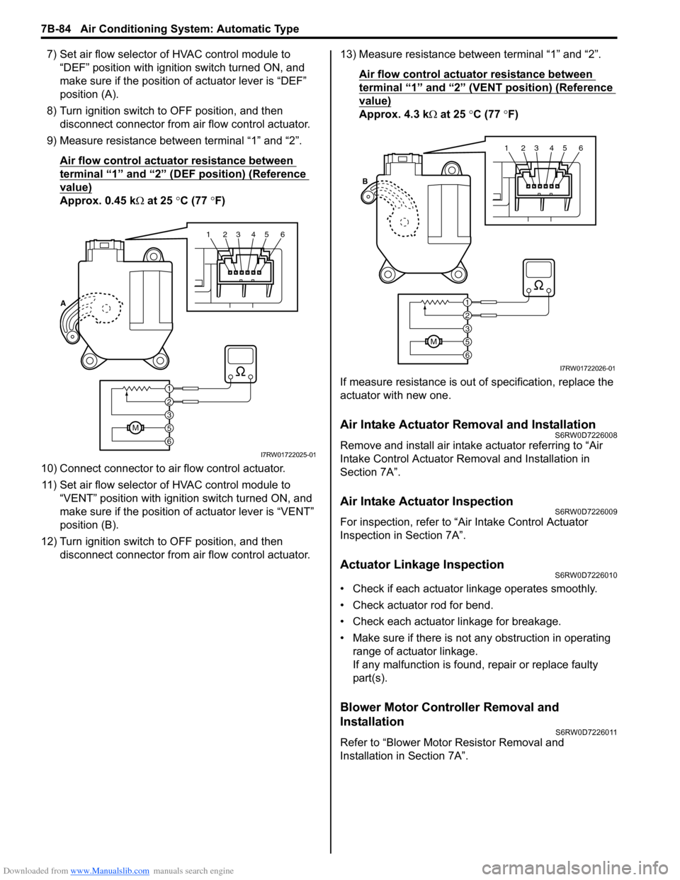
9) Measure resistance between terminal “1” and “2”.
Air flow control actuator resistance between
terminal “1” and “2” (DEF position) (Reference
value)
Approx. 0.45 kΩ at 25 °C (77 °F)
10) Connect connector to air flow control actuator.
11) Set air flow selector of HVAC control module to
“VENT” position with ignition switch turned ON, and
make sure if the position of actuator lever is “VENT”
position (B).
12) Turn ignition switch to OFF position, and then
disconnect connector from air flow control actuator.13) Measure resistance between terminal “1” and “2”.
Air flow control actuator resistance between
terminal “1” and “2” (VENT position) (Reference
value)
Approx. 4.3 kΩ at 25 °C (77 °F)
If measure resistance is out of specification, replace the
actuator with new one.
Air Intake Actuator Removal and InstallationS6RW0D7226008
Remove and install air intake actuator referring to “Air
Intake Control Actuator Removal and Installation in
Section 7A”.
Air Intake Actuator InspectionS6RW0D7226009
For inspection, refer to “Air Intake Control Actuator
Inspection in Section 7A”.
Actuator Linkage InspectionS6RW0D7226010
• Check if each actuator linkage operates smoothly.
• Check actuator rod for bend.
• Check each actuator linkage for breakage.
• Make sure if there is not any obstruction in operating
range of actuator linkage.
If any malfunction is found, repair or replace faulty
part(s).
Blower Motor Controller Removal and
Installation
S6RW0D7226011
Refer to “Blower Motor Resistor Removal and
Installation in Section 7A”.
123456
6
M5
3
2
1 A
I7RW01722025-01
123456
6
M5
3
2
1 B
I7RW01722026-01
Page 1025 of 1556
Downloaded from www.Manualslib.com manuals search engine Air Conditioning System: Automatic Type 7B-85
Blower Motor Controller InspectionS6RW0D7226012
1) Check internal circuit of controller for resistance as
follows.
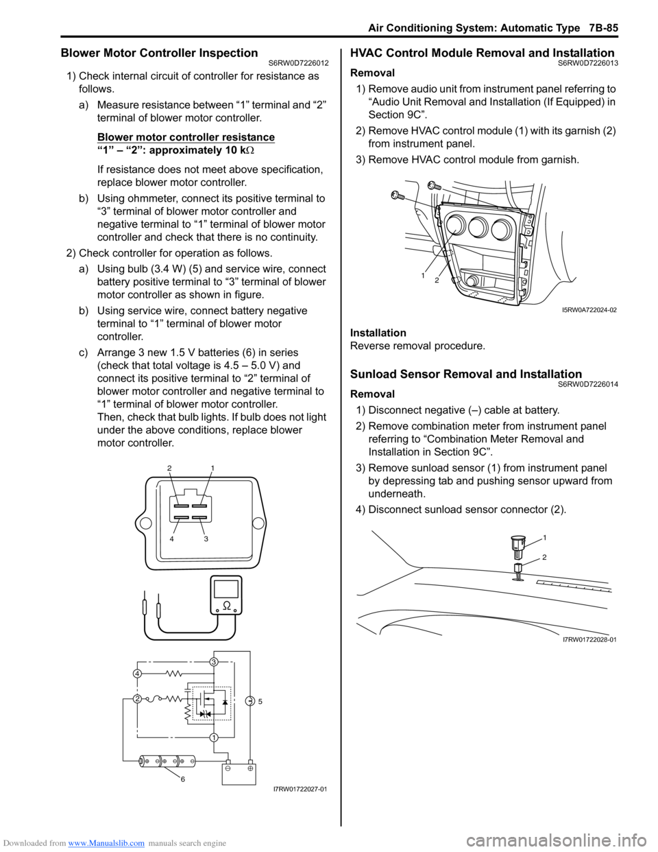
a) Measure resistance between “1” terminal and “2”
terminal of blower motor controller.
Blower motor controller resistance
“1” – “2”: approximately 10 kΩ
If resistance does not meet above specification,
replace blower motor controller.
b) Using ohmmeter, connect its positive terminal to
“3” terminal of blower motor controller and
negative terminal to “1” terminal of blower motor
controller and check that there is no continuity.
2) Check controller for operation as follows.
a) Using bulb (3.4 W) (5) and service wire, connect
battery positive terminal to “3” terminal of blower
motor controller as shown in figure.
b) Using service wire, connect battery negative
terminal to “1” terminal of blower motor
controller.
c) Arrange 3 new 1.5 V batteries (6) in series
(check that total voltage is 4.5 – 5.0 V) and
connect its positive terminal to “2” terminal of
blower motor controller and negative terminal to
“1” terminal of blower motor controller.
Then, check that bulb lights. If bulb does not light
under the above conditions, replace blower
motor controller.
HVAC Control Module Removal and InstallationS6RW0D7226013
Removal
1) Remove audio unit from instrument panel referring to
“Audio Unit Removal and Installation (If Equipped) in
Section 9C”.
2) Remove HVAC control module (1) with its garnish (2)
from instrument panel.
3) Remove HVAC control module from garnish.
Installation
Reverse removal procedure.
Sunload Sensor Removal and InstallationS6RW0D7226014
Removal
1) Disconnect negative (–) cable at battery.
2) Remove combination meter from instrument panel
referring to “Combination Meter Removal and
Installation in Section 9C”.
3) Remove sunload sensor (1) from instrument panel
by depressing tab and pushing sensor upward from
underneath.
4) Disconnect sunload sensor connector (2).
21
43
3
1 2 4
5
6I7RW01722027-01
12
I5RW0A722024-02
1
2
I7RW01722028-01
Page 1026 of 1556
Downloaded from www.Manualslib.com manuals search engine 7B-86 Air Conditioning System: Automatic Type
Installation
Reverse removal procedure noting the following
instructions.
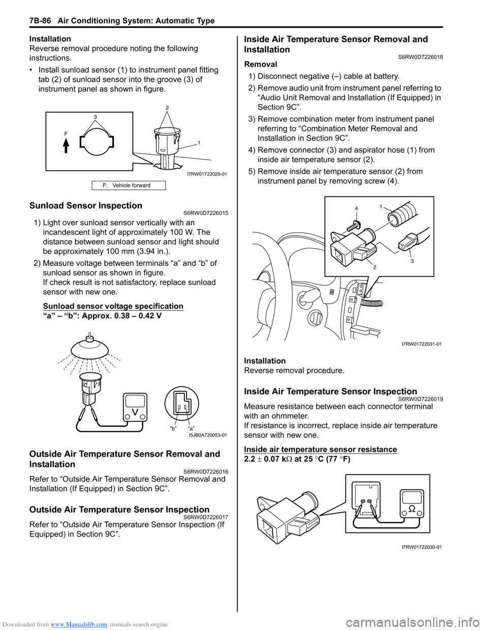
• Install sunload sensor (1) to instrument panel fitting
tab (2) of sunload sensor into the groove (3) of
instrument panel as shown in figure.
Sunload Sensor InspectionS6RW0D7226015
1) Light over sunload sensor vertically with an
incandescent light of approximately 100 W. The
distance between sunload sensor and light should
be approximately 100 mm (3.94 in.).
2) Measure voltage between terminals “a” and “b” of
sunload sensor as shown in figure.
If check result is not satisfactory, replace sunload
sensor with new one.
Sunload sensor voltage specification
“a” – “b”: Approx. 0.38 – 0.42 V
Outside Air Temperature Sensor Removal and
Installation
S6RW0D7226016
Refer to “Outside Air Temperature Sensor Removal and
Installation (If Equipped) in Section 9C”.
Outside Air Temperature Sensor InspectionS6RW0D7226017
Refer to “Outside Air Temperature Sensor Inspection (If
Equipped) in Section 9C”.
Inside Air Temperature Sensor Removal and
Installation
S6RW0D7226018
Removal
1) Disconnect negative (–) cable at battery.
2) Remove audio unit from instrument panel referring to
“Audio Unit Removal and Installation (If Equipped) in
Section 9C”.
3) Remove combination meter from instrument panel
referring to “Combination Meter Removal and
Installation in Section 9C”.
4) Remove connector (3) and aspirator hose (1) from
inside air temperature sensor (2).
5) Remove inside air temperature sensor (2) from
instrument panel by removing screw (4).
Installation
Reverse removal procedure.
Inside Air Temperature Sensor InspectionS6RW0D7226019
Measure resistance between each connector terminal
with an ohmmeter.
If resistance is incorrect, replace inside air temperature
sensor with new one.
Inside air temperature sensor resistance
2.2 ± 0.07 kΩ at 25 °C (77 °F)
F: Vehicle forward
2
F
1
3
I7RW01722029-01
“b” “a”I5JB0A720053-01
1
23 4
I7RW01722031-01
I7RW01722030-01
Page 1037 of 1556
Downloaded from www.Manualslib.com manuals search engine Seat Belts: 8A-6
Front Seat Belt InspectionS6RW0D8106003
WARNING!
• Never attempt to disassemble or repair the
seat belt pretensioner (retractor). If any
abnormality is found, be sure to replace it
with new one as an assembly.
• Be sure to read “Precautions on Service
and Diagnosis of Seat Belt”, before
starting to work and observe every
precaution during work. Neglecting them
may result in personal injury or
unactivation of the seat belt pretensioner
when necessary.
• Never measure resistance of pretensioner
or disassemble it. Otherwise, personal
injury may result.
CAUTION!
If seat belt pretensioner (retractor) was
dropped from a height of 30 cm (1 ft) or more,
it should be replaced.
Seat belts and attaching parts can affect the vital
components and systems of a vehicle.
Therefore, they should be inspected carefully and
replaced with genuine parts only.
Seat Belt
• The seat belt webbing or strap should be free from
damage.
Retractor (with Seat Belt Pretensioner)
1) Let the seat belt retract fully to confirm its easy
retraction.
• The retractor should lock webbing when pulled
quickly.
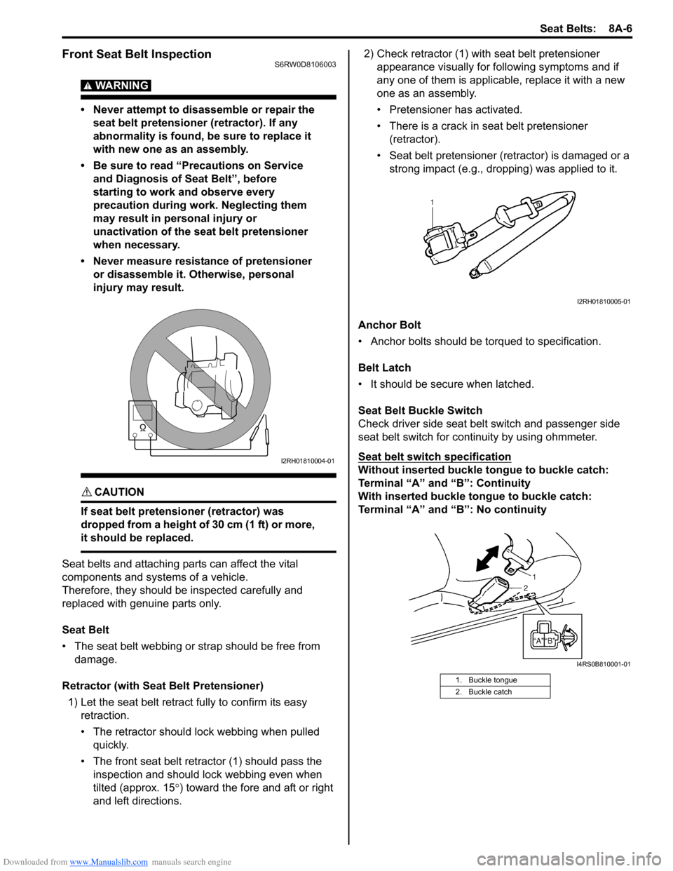
• The front seat belt retractor (1) should pass the
inspection and should lock webbing even when
tilted (approx. 15°) toward the fore and aft or right
and left directions.2) Check retractor (1) with seat belt pretensioner
appearance visually for following symptoms and if
any one of them is applicable, replace it with a new
one as an assembly.
• Pretensioner has activated.
• There is a crack in seat belt pretensioner
(retractor).
• Seat belt pretensioner (retractor) is damaged or a
strong impact (e.g., dropping) was applied to it.
Anchor Bolt
• Anchor bolts should be torqued to specification.
Belt Latch
• It should be secure when latched.
Seat Belt Buckle Switch
Check driver side seat belt switch and passenger side
seat belt switch for continuity by using ohmmeter.
Seat belt switch specification
Without inserted buckle tongue to buckle catch:
Terminal “A” and “B”: Continuity
With inserted buckle tongue to buckle catch:
Terminal “A” and “B”: No continuityI2RH01810004-01
1. Buckle tongue
2. Buckle catch
I2RH01810005-01
I4RS0B810001-01
Page 1043 of 1556
Downloaded from www.Manualslib.com manuals search engine Air Bag System: 8B-4
• Never attempt to disassemble the seat belt
pretensioners (retractor assembly).
• If any abnormality is found, be sure to replace it with
new one as an assembly.
• When an abnormality is noted as existing in the live
(inactivated) seat belt pretensioner, be sure to activate
it before discarding it.
• When grease, cleaning agent oil, water, etc., got on
the seat belt pretensioners (retractor assembly), wipe
it off immediately with a dry cloth.
• If seat belt pretensioner was dropped from a height of
30 cm (1 ft) or more, it should be replaced with a new
one as an assembly.
WARNING!
• For handling and storage of a live seat belt
pretensioner, select a place where the
ambient temperature below 65 °C (150 °F),
without high humidity and away from
electric noise.
• Never carry the seat belt pretensioner by
webbing.
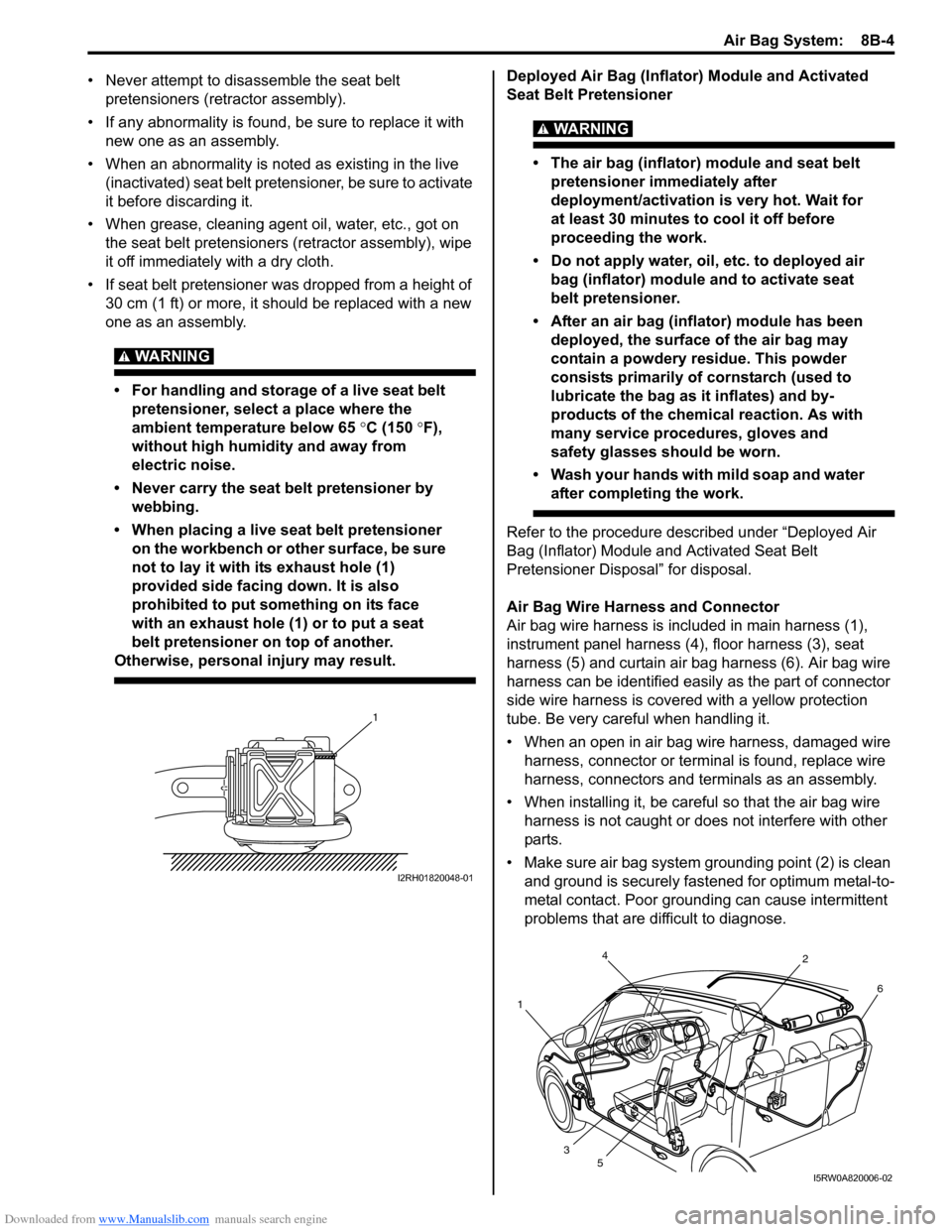
• When placing a live seat belt pretensioner
on the workbench or other surface, be sure
not to lay it with its exhaust hole (1)
provided side facing down. It is also
prohibited to put something on its face
with an exhaust hole (1) or to put a seat
belt pretensioner on top of another.
Otherwise, personal injury may result.
Deployed Air Bag (Inflator) Module and Activated
Seat Belt Pretensioner
WARNING!
• The air bag (inflator) module and seat belt
pretensioner immediately after
deployment/activation is very hot. Wait for
at least 30 minutes to cool it off before
proceeding the work.
• Do not apply water, oil, etc. to deployed air
bag (inflator) module and to activate seat
belt pretensioner.
• After an air bag (inflator) module has been
deployed, the surface of the air bag may
contain a powdery residue. This powder
consists primarily of cornstarch (used to
lubricate the bag as it inflates) and by-
products of the chemical reaction. As with
many service procedures, gloves and
safety glasses should be worn.
• Wash your hands with mild soap and water
after completing the work.
Refer to the procedure described under “Deployed Air
Bag (Inflator) Module and Activated Seat Belt
Pretensioner Disposal” for disposal.
Air Bag Wire Harness and Connector
Air bag wire harness is included in main harness (1),
instrument panel harness (4), floor harness (3), seat
harness (5) and curtain air bag harness (6). Air bag wire
harness can be identified easily as the part of connector
side wire harness is covered with a yellow protection
tube. Be very careful when handling it.
• When an open in air bag wire harness, damaged wire
harness, connector or terminal is found, replace wire
harness, connectors and terminals as an assembly.
• When installing it, be careful so that the air bag wire
harness is not caught or does not interfere with other
parts.
• Make sure air bag system grounding point (2) is clean
and ground is securely fastened for optimum metal-to-
metal contact. Poor grounding can cause intermittent
problems that are difficult to diagnose.
1
I2RH01820048-01
4
12
6
3
5
I5RW0A820006-02
Page 1048 of 1556
![SUZUKI SX4 2006 1.G Service Workshop Manual Downloaded from www.Manualslib.com manuals search engine 8B-9 Air Bag System:
Terminal arrangement of SDM (viewed from harness side)
[A]: Shorting bar 11. BCM 25. Driver seat belt pretensioner
[B]: C SUZUKI SX4 2006 1.G Service Workshop Manual Downloaded from www.Manualslib.com manuals search engine 8B-9 Air Bag System:
Terminal arrangement of SDM (viewed from harness side)
[A]: Shorting bar 11. BCM 25. Driver seat belt pretensioner
[B]: C](/manual-img/20/7612/w960_7612-1047.png)
Downloaded from www.Manualslib.com manuals search engine 8B-9 Air Bag System:
Terminal arrangement of SDM (viewed from harness side)
[A]: Shorting bar 11. BCM 25. Driver seat belt pretensioner
[B]: Connector 12. Combination meter 26. Passenger seat belt pretensioner
[C]: Junction block with BCM model 13. “AIR BAG” warning light27. Driver side-air bag (inflator) module (8-channel system)
[D]: Junction block without BCM model 14. Light driver 28. Passenger side-air bag (inflator) module (8-channel system)
1. Battery 15. SDM 29. Driver side curtain-air bag (inflator) module (8-channel
system)
2. Main fuse 16. To HVAC control module (auto A/C model) 30. Passenger side curtain-air bag (inflator) module (8-channel
system)
3. Fuse 17. Data link connector (DLC) 31. Safing power driver
4. Individual circuit fuse box No.1 18. Forward impact-sensor 32. X-Y-G (longitudinal / lateral acceleration)
5. “IGN” fuse 19. Driver side impact-sensor (8-channel
system)33. DC / DC converter
6. Ignition switch 20. Passenger side impact-sensor (8-channel
system)34. Mechanical longitudinal G sensor (switch)
7. Junction block assembly 21. Ground for air bag system 35. Back up capacitor
8. “DOME” fuse 22. Contact coil assembly
9. “METER” fuse 23. Driver air bag (inflator) module
10. “A/B” fuse 24. Passenger air bag (inflator) module
1
2 3 4 5 6 7 8 9 10 11 12 13 14 15 16 17 18 19 20 21 22 23 24 25 26
27 28 29 30 31 32 33 34 35 36 37 38 39 40 41 42 43 44 45 46 47 48 49 50 51
1
I7RW01822003-02
1. SDM Connector “L04”