Downloaded from www.Manualslib.com manuals search engine Engine General Information and Diagnosis: 1A-109
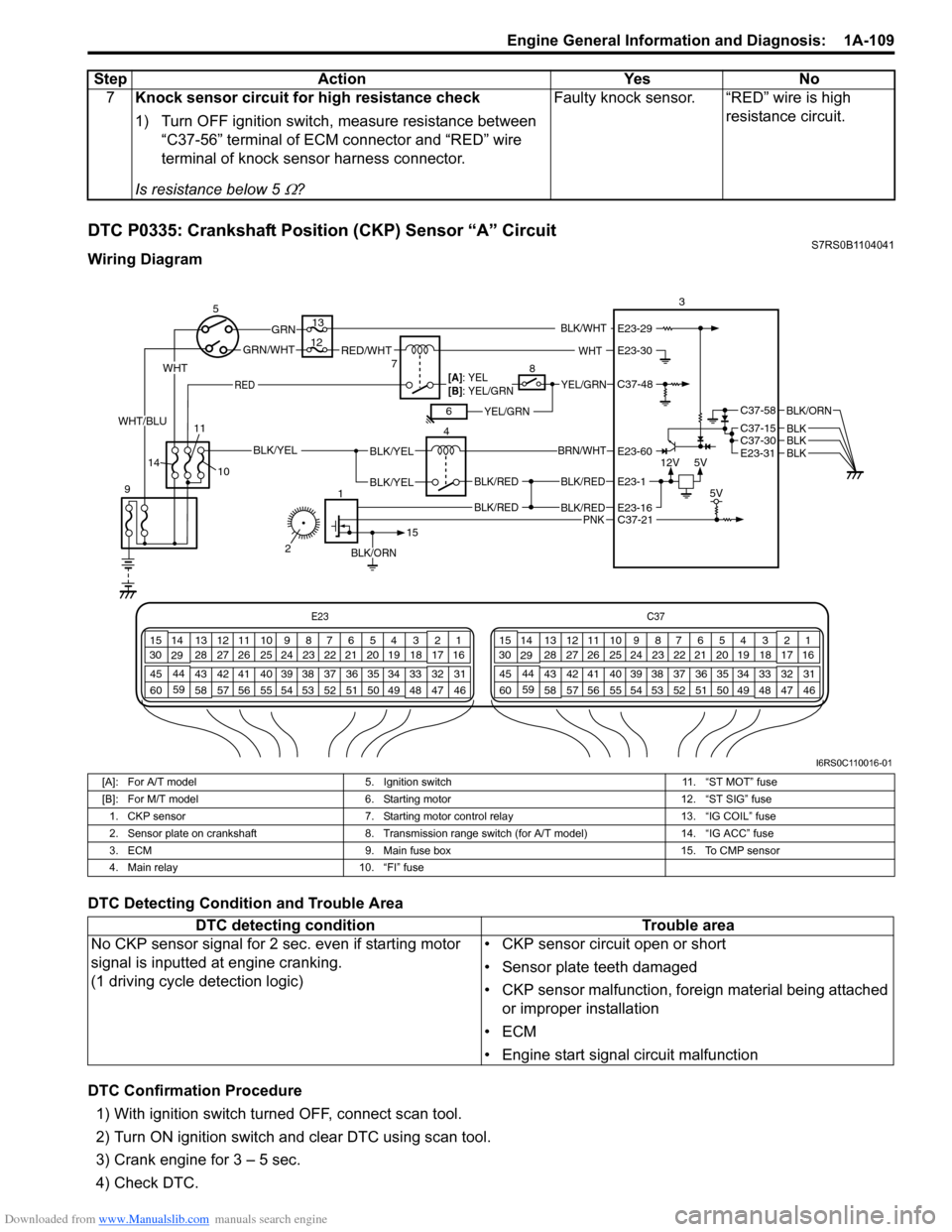
DTC P0335: Crankshaft Position (CKP) Sensor “A” CircuitS7RS0B1104041
Wiring Diagram
DTC Detecting Condition and Trouble Area
DTC Confirmation Procedure1) With ignition switch turned OFF, connect scan tool.
2) Turn ON ignition switch and clear DTC using scan tool.
3) Crank engine for 3 – 5 sec.
4) Check DTC. 7
Knock sensor circuit for high resistance check
1) Turn OFF ignition switch, measure resistance between
“C37-56” terminal of ECM connector and “RED” wire
terminal of knock sensor harness connector.
Is resistance below 5
Ω? Faulty knock sensor. “RED” wire is high
resistance circuit.
Step
Action YesNo
E23 C37
34
1819
567
1011
17
20
47 46
495051
2122
52 16
25 9
24
14
29
55
57 54 53
59
60 58 2
262728
15
30
56 4832 31
34353637
40
42 39 38
44
45 43 41 331
1213
238
34
1819
567
1011
17
20
47 46
495051
2122
52 16
25 9
24
14
29
55
57 54 53
59
60 58 2
262728
15
30
56 4832 31
34353637
40
42 39 38
44
45 43 41 331
1213
238
12V
5V
BLK/RED
BLK/RED
BLK/YELBLK/YEL
BLK/YEL
BRN/WHT
5
9 4
13
3
C37-30C37-15
C37-58
E23-31
BLK/ORN
BLKBLKBLK
10
BLK/RED
BLK/RED
E23-16
E23-60
E23-1
BLK/ORN
1
15
C37-21 5V
7RED/WHTGRN/WHT
GRN
RED
BLK/WHT
YEL/GRN
YEL/GRN
WHT
[A]: YEL
[B]: YEL/GRN
68
12
11
14
PNK
2
WHT
WHT/BLU
C37-48
E23-30
E23-29
I6RS0C110016-01
[A]: For A/T model 5. Ignition switch 11. “ST MOT” fuse
[B]: For M/T model 6. Starting motor 12. “ST SIG” fuse
1. CKP sensor 7. Starting motor control relay 13. “IG COIL” fuse
2. Sensor plate on crankshaft 8. Transmission range switch (for A/T model) 14. “IG ACC” fuse
3. ECM 9. Main fuse box 15. To CMP sensor
4. Main relay 10. “FI” fuse
DTC detecting condition Trouble area
No CKP sensor signal for 2 se c. even if starting motor
signal is inputted at engine cranking.
(1 driving cycle detection logic) • CKP sensor circuit open or short
• Sensor plate teeth damaged
• CKP sensor malfunction, foreign material being attached
or improper installation
•ECM
• Engine start signal circuit malfunction
Downloaded from www.Manualslib.com manuals search engine Air Conditioning System: Manual Type 7B-9
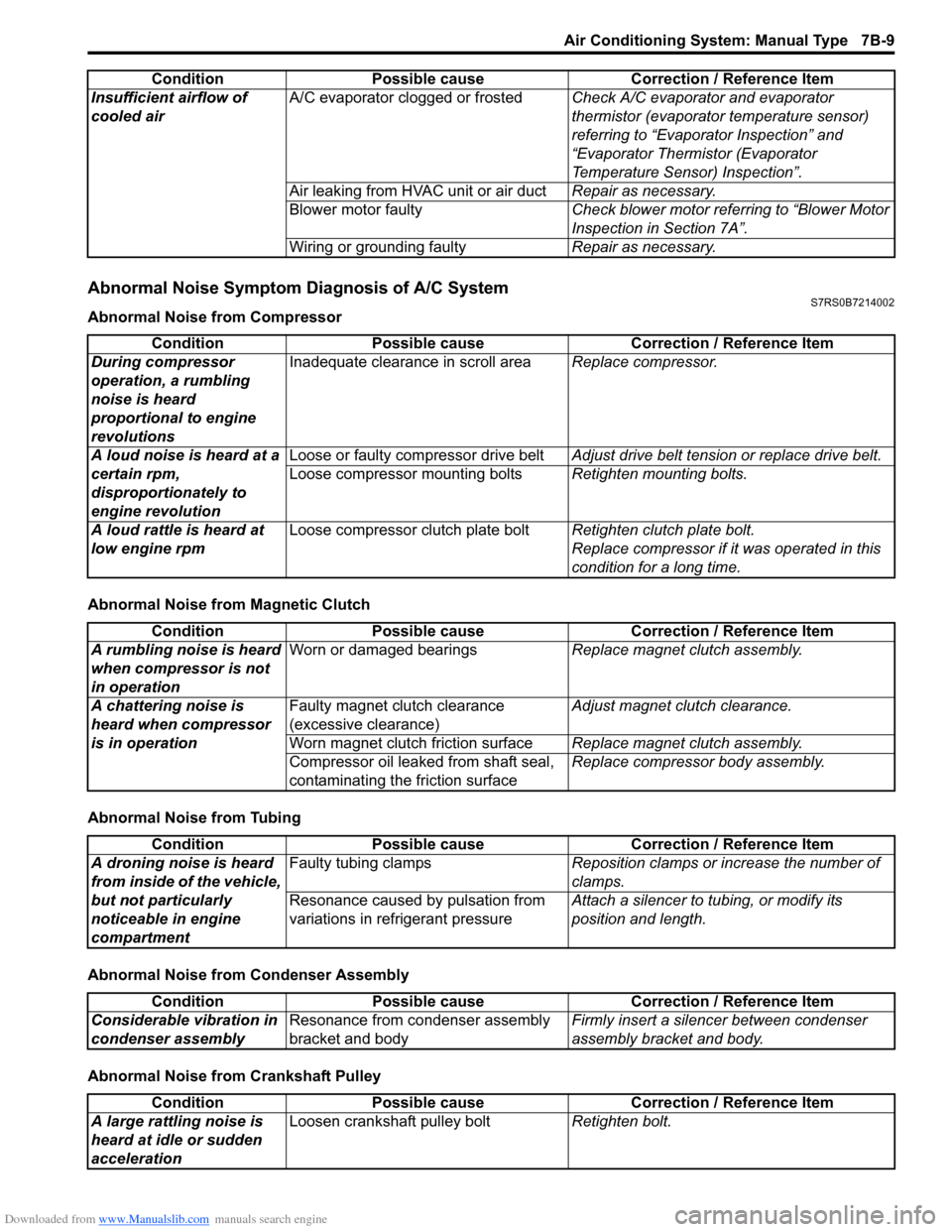
Abnormal Noise Symptom Diagnosis of A/C SystemS7RS0B7214002
Abnormal Noise from Compressor
Abnormal Noise from Magnetic Clutch
Abnormal Noise from Tubing
Abnormal Noise from Condenser Assembly
Abnormal Noise from Crankshaft PulleyInsufficient airflow of
cooled air
A/C evaporator clogged or frosted
Check A/C evaporator and evaporator
thermistor (evaporator temperature sensor)
referring to “Evaporator Inspection” and
“Evaporator Thermistor (Evaporator
Temperature Sensor) Inspection”.
Air leaking from HVAC unit or air duct Repair as necessary.
Blower motor faulty Check blower motor referring to “Blower Motor
Inspection in Section 7A”.
Wiring or grounding faulty Repair as necessary.
Condition Possible cause Correction / Reference Item
Condition
Possible cause Correction / Reference Item
During compressor
operation, a rumbling
noise is heard
proportional to engine
revolutions Inadequate clearance in scroll area
Replace compressor.
A loud noise is heard at a
certain rpm,
disproportionately to
engine revolution Loose or faulty compressor drive belt
Adjust drive belt tension or replace drive belt.
Loose compressor mounting bolts Retighten mounting bolts.
A loud rattle is heard at
low engine rpm Loose compressor clutch plate bolt
Retighten clutch plate bolt.
Replace compressor if it was operated in this
condition for a long time.
Condition Possible cause Correction / Reference Item
A rumbling noise is heard
when compressor is not
in operation Worn or damaged bearings
Replace magnet clutch assembly.
A chattering noise is
heard when compressor
is in operation Faulty magnet clutch clearance
(excessive clearance)
Adjust magnet clutch clearance.
Worn magnet clutch friction surface Replace magnet clutch assembly.
Compressor oil leaked from shaft seal,
contaminating the friction surface Replace compressor body assembly.
Condition
Possible cause Correction / Reference Item
A droning noise is heard
from inside of the vehicle,
but not particularly
noticeable in engine
compartment Faulty tubing clamps
Reposition clamps or increase the number of
clamps.
Resonance caused by pulsation from
variations in re frigerant pressure Attach a silencer to tubing, or modify its
position and length.
Condition
Possible cause Correction / Reference Item
Considerable vibration in
condenser assembly Resonance from condenser assembly
bracket and body Firmly insert a silenc
er between condenser
assembly bracket and body.
Condition Possible cause Correction / Reference Item
A large rattling noise is
heard at idle or sudden
acceleration Loosen crankshaft pulley bolt
Retighten bolt.