2006 SUZUKI SWIFT Pillar
[x] Cancel search: PillarPage 30 of 1496
![SUZUKI SWIFT 2006 2.G Service Workshop Manual Downloaded from www.Manualslib.com manuals search engine 0A-9 General Information:
[A]
12
4 5
6
7 8
9
3
I4RS0B010002-03
1. Air bag label on driver air bag (inflator) module 6. Air bag label on SDM
2 SUZUKI SWIFT 2006 2.G Service Workshop Manual Downloaded from www.Manualslib.com manuals search engine 0A-9 General Information:
[A]
12
4 5
6
7 8
9
3
I4RS0B010002-03
1. Air bag label on driver air bag (inflator) module 6. Air bag label on SDM
2](/manual-img/20/7607/w960_7607-29.png)
Downloaded from www.Manualslib.com manuals search engine 0A-9 General Information:
[A]
12
4 5
6
7 8
9
3
I4RS0B010002-03
1. Air bag label on driver air bag (inflator) module 6. Air bag label on SDM
2. Air bag label on combination switch and contact coil assembly7. Pretensioner label on seat belt retractor
3. Air bag label on passenger air bag (inflator) module 8. Child seat label (if equipped)
4. Air bag label on side air bag (inflator) module (if equipped) 9. Side/Curtain air bag label on pillar (both right and left sides) (if equipped)
5. Air bag label on curtain air bag (inflator) module (if equipped) [A]: These labels are attached on vehicle equipped with air ba g system only.
Page 468 of 1496
Downloaded from www.Manualslib.com manuals search engine 2D-1 Wheels and Tires:
Suspension
Wheels and Tires
Precautions
Precaution for Emergency Flat Tire Repair KitS7RS0B2400001
WARNING!
Flat tire repair sealant including in kit is
harmful. Be sure to observe the following.
Otherwise, your health may be ruined.
• If swallowed, get medical attention immediately.
• Keep out of reach of children.
• Select place where there is good ventilation for this work.
• If it enters eye or contacts skin, wash thoroughly with water. If anything
abnormal still rema ins, get medical
attention immediately.
• Do not discard tire containing sealant as it is. Make sure to remove sealant from tire,
referring to “Tire Repair for Emergency
Repaired-Tire with Sealant”.
• Dispose of sealant as waste oil.
CAUTION!
• When tire repaired with Emergency Flat Tire Repair Kit is brought in, remove flat
tire repair sealant from tire and repair flat
tire referring to “Tire Repair for Emergency
Repaired-Tire with Sealant”.
• Sealant expiration date is printed on bottle label. if it expires, sealant should be
replaced with a new one to ensure
emergency flat tire repair.
General Description
Tires DescriptionS7RS0B2401001
The tire is of tubeless type. The tire is designed to
operate satisfactorily with loads up to the full rated load
capacity when inflated to the recommended inflation
pressures.
Correct tire pressures and driving habits have an
important influence on tire life. Heavy cornering,
excessively rapid acceleration, and unnecessary sharp
braking increase tire wear.
Tire Placard
The “Tire Placard” is located on the left or right door lock
pillar and should be referred to tire information.
The placard lists the maximum load, tire size and cold
tire pressure where applicable.
NOTE
Whether rim size and/or maximum load are
listed or not depends on regulations of each
country.
Inflation of Tires
The pressure recommended for any model is carefully
calculated to give a satisfacto ry ride, stability, steering,
tread wear, tire life and resistance to bruises.
Tire pressure, with tires cold, (after vehicle has set for 3
hours or more, or driven less than one mile) should be
checked monthly or before any extended trip. Set to the
specifications on the “Tire Placard” located on the left
door lock pillar.
It is normal for tire pressure to increase when the tires
become hot during driving.
Do not bleed or reduce tire pressure after driving.
Bleeding reduces the “Cold Inflation Pressure”.
Higher than recommended pressure can cause:
• Hard ride
• Tire bruising or carcass damage
• Rapid tread wear at center of tire
Unequal pressure on same axle can cause:
• Uneven braking
• Steering lead
• Reduced handling
• Swerve on acceleration
Page 1035 of 1496
Downloaded from www.Manualslib.com manuals search engine Seat Belts: 8A-4
Front Seat Belt Removal and InstallationS7RS0B8106002
WARNING!
• Never attempt to disassemble or repair the seat belt pretensioner (retractor
assembly). If any abnormality is found, be
sure to replace it with new one as an
assembly.
• Be sure to read “Precautions on Service and Diagnosis of Seat Belt” before starting
to work and observe every precaution
during work. Ne glecting them may result in
personal injury or una ctivation of the seat
belt pretensioner when necessary.
Removal
1) Disconnect negative (–) cable at battery.
2) Disable air bag system. Refer to “Disabling Air Bag System in Section 8B”.
3) Remove center pillar lower trim.
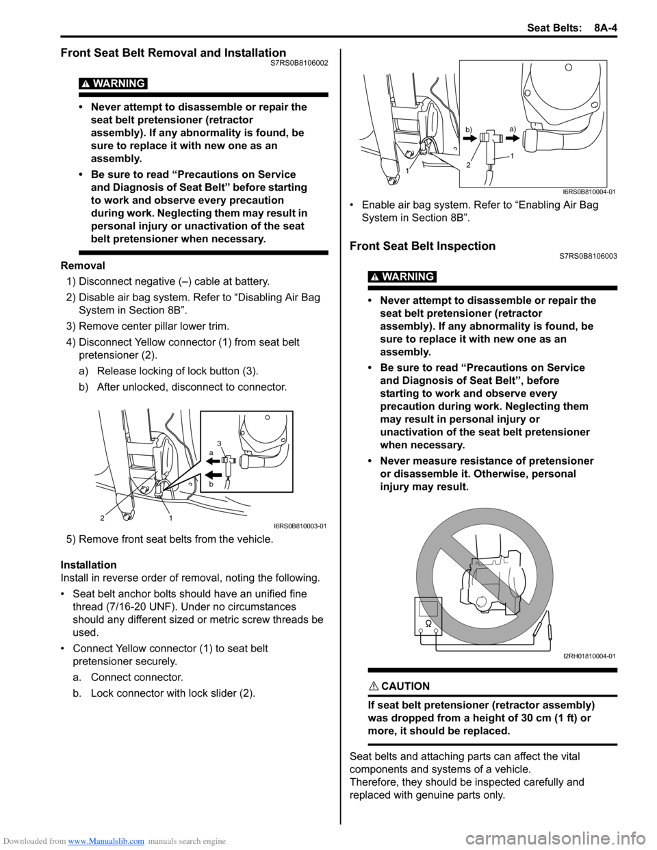
4) Disconnect Yellow connector (1) from seat belt pretensioner (2).
a) Release locking of lock button (3).
b) After unlocked, disconnect to connector.
5) Remove front seat belts from the vehicle.
Installation
Install in reverse order of removal, noting the following.
• Seat belt anchor bolts should have an unified fine thread (7/16-20 UNF). Under no circumstances
should any different sized or metric screw threads be
used.
• Connect Yellow connector (1) to seat belt pretensioner securely.
a. Connect connector.
b. Lock connector with lock slider (2). • Enable air bag system. Refer to “Enabling Air Bag
System in Section 8B”.
Front Seat Belt InspectionS7RS0B8106003
WARNING!
• Never attempt to disassemble or repair the seat belt pretensioner (retractor
assembly). If any abnormality is found, be
sure to replace it with new one as an
assembly.
• Be sure to read “Precautions on Service and Diagnosis of Seat Belt”, before
starting to work and observe every
precaution during work. Neglecting them
may result in personal injury or
unactivation of the seat belt pretensioner
when necessary.
• Never measure resistance of pretensioner or disassemble it. Otherwise, personal
injury may result.
CAUTION!
If seat belt pretensioner (retractor assembly)
was dropped from a height of 30 cm (1 ft) or
more, it should be replaced.
Seat belts and attaching parts can affect the vital
components and systems of a vehicle.
Therefore, they should be inspected carefully and
replaced with genuine parts only.
a
b
21 3I6RS0B810003-01
1
1
2
b)
a)
I6RS0B810004-01
I2RH01810004-01
Page 1095 of 1496
Downloaded from www.Manualslib.com manuals search engine Air Bag System: 8B-57
CAUTION!
• Be sure to perform “Air Bag Diagnostic System Check” before starting diagnosis according to flow.
• When measurement of resistance or voltage is required in this flow, use a tester along with a correct terminal adapter from special tool (Connector test adapter kit).
• When a check for proper connection is required, refer to “Inspection of Intermittent and Poor Connections”.
• If there is open circuit in the air bag wire harnes s, connector or terminal is found damaged, replace
the wire harness, connector and terminal as an assembly.
DTC Will Set when
The resistance of driver or passenger seat belt pretensioner initiator circuit is above a specified value for specified
time.
Flow Test Description
Step 1: Check if malfunction is in seat belt pretensioner.
Step 2: Check seat belt pretensioner initiator circuit.
DTC Troubleshooting
Step Action YesNo
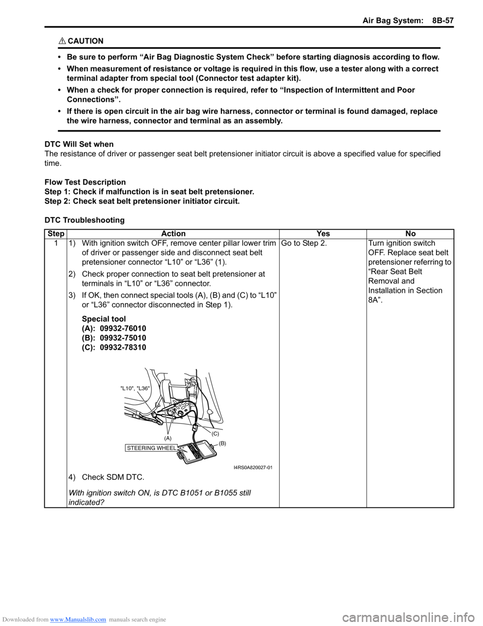
1 1) With ignition switch OFF, re move center pillar lower trim
of driver or passenger side and disconnect seat belt
pretensioner connector “L10” or “L36” (1).
2) Check proper connection to seat belt pretensioner at terminals in “L10” or “L36” connector.
3) If OK, then connect special tools (A), (B) and (C) to “L10” or “L36” connector disconnected in Step 1).
Special tool
(A): 09932-76010
(B): 09932-75010
(C): 09932-78310
4) Check SDM DTC.
With ignition switch ON, is DTC B1051 or B1055 still
indicated? Go to Step 2.
Turn ignition switch
OFF. Replace seat belt
pretensioner referring to
“Rear Seat Belt
Removal and
Installation in Section
8A”.
STEERING WHEEL(B)
(C)
(A)
"L10", "L36"
I4RS0A820027-01
Page 1097 of 1496
Downloaded from www.Manualslib.com manuals search engine Air Bag System: 8B-59
CAUTION!
• Be sure to perform “Air Bag Diagnostic System Check” before starting diagnosis according to flow.
• When measurement of resistance or voltage is required in this flow, use a tester along with a correct terminal adapter from special tool (Connector test adapter kit).
• When a check for proper connection is required, refer to “Inspection of Intermittent and Poor Connections”.
• If there is open circuit in the air bag wire harnes s, connector or terminal is found damaged, replace
the wire harness, connector and terminal as an assembly.
DTC Will Set when
The resistance of driver or passenger seat belt pretensioner initiator circuit is below a specified value for specified
time.
Flow Test Description
Step 1: Check if malfunction is in seat belt pretensioner.
Step 2: Check seat belt pretensioner initiator circuit.
DTC Troubleshooting
Step Action YesNo
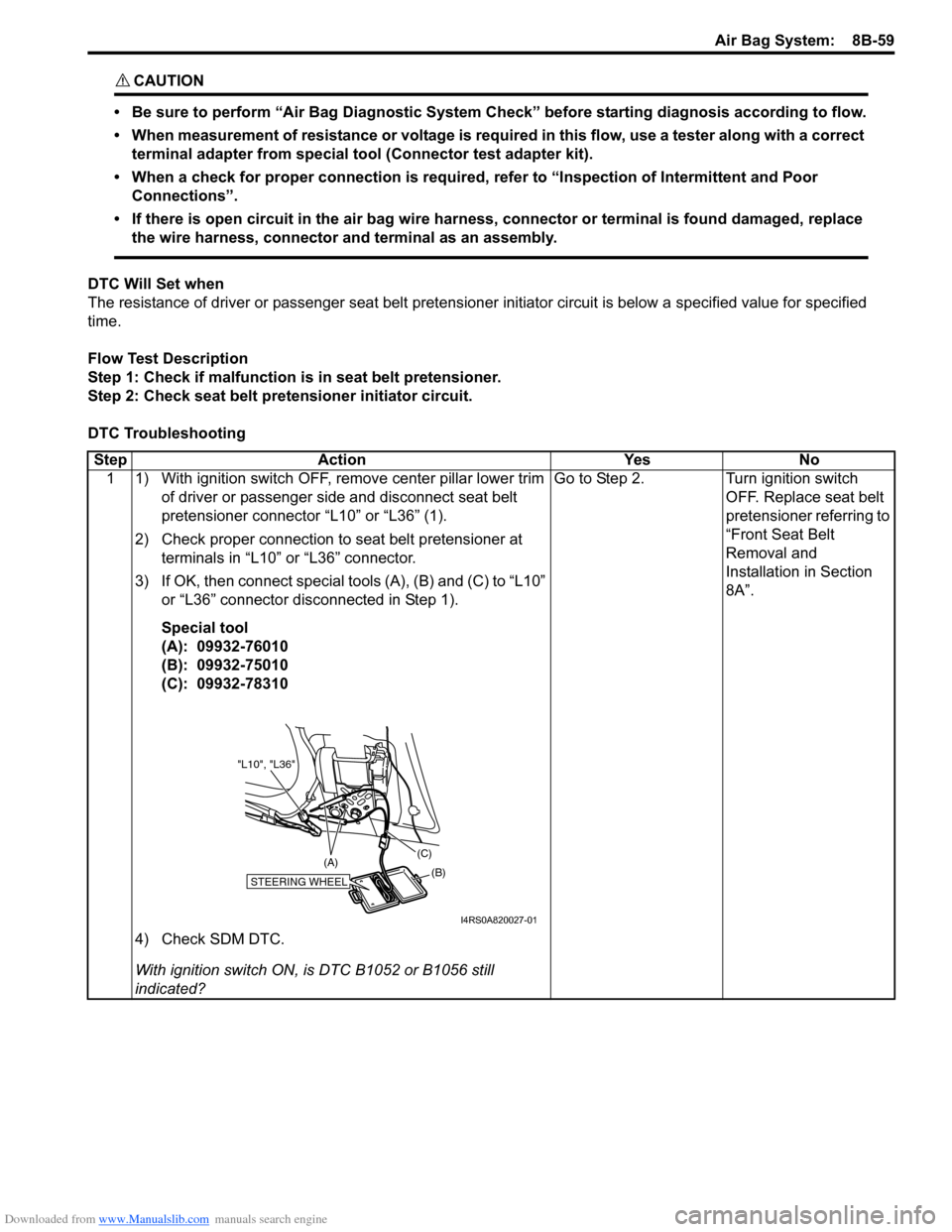
1 1) With ignition switch OFF, re move center pillar lower trim
of driver or passenger side and disconnect seat belt
pretensioner connector “L10” or “L36” (1).
2) Check proper connection to seat belt pretensioner at terminals in “L10” or “L36” connector.
3) If OK, then connect special tools (A), (B) and (C) to “L10” or “L36” connector disconnected in Step 1).
Special tool
(A): 09932-76010
(B): 09932-75010
(C): 09932-78310
4) Check SDM DTC.
With ignition switch ON, is DTC B1052 or B1056 still
indicated? Go to Step 2.
Turn ignition switch
OFF. Replace seat belt
pretensioner referring to
“Front Seat Belt
Removal and
Installation in Section
8A”.
STEERING WHEEL(B)
(C)
(A)
"L10", "L36"
I4RS0A820027-01
Page 1099 of 1496
Downloaded from www.Manualslib.com manuals search engine Air Bag System: 8B-61
CAUTION!
• Be sure to perform “Air Bag Diagnostic System Check” before starting diagnosis according to flow.
• When measurement of resistance or voltage is required in this flow, use a tester along with a correct terminal adapter from special tool (Connector test adapter kit).
• When a check for proper connection is required, refer to “Inspection of Intermittent and Poor Connections”.
• If there is open circuit in the air bag wire harnes s, connector or terminal is found damaged, replace
the wire harness, connector and terminal as an assembly.
DTC Will Set when
The voltage measured at driver or passenger seat belt pr etensioner initiator circuit is below a specified value for
specified time.
Flow Test Description
Step 1: Check if malfunction is in seat belt pretensioner.
Step 2: Check seat belt pretensioner initiator circuit.
DTC Troubleshooting
Step Action YesNo
1 1) With ignition switch OFF, re move center pillar lower trim
of driver or passenger side and disconnect seat belt
pretensioner connector “L10” or “L36” (1).
2) Check proper connection to seat belt pretensioner at terminals in “L10” or “L36” connector.
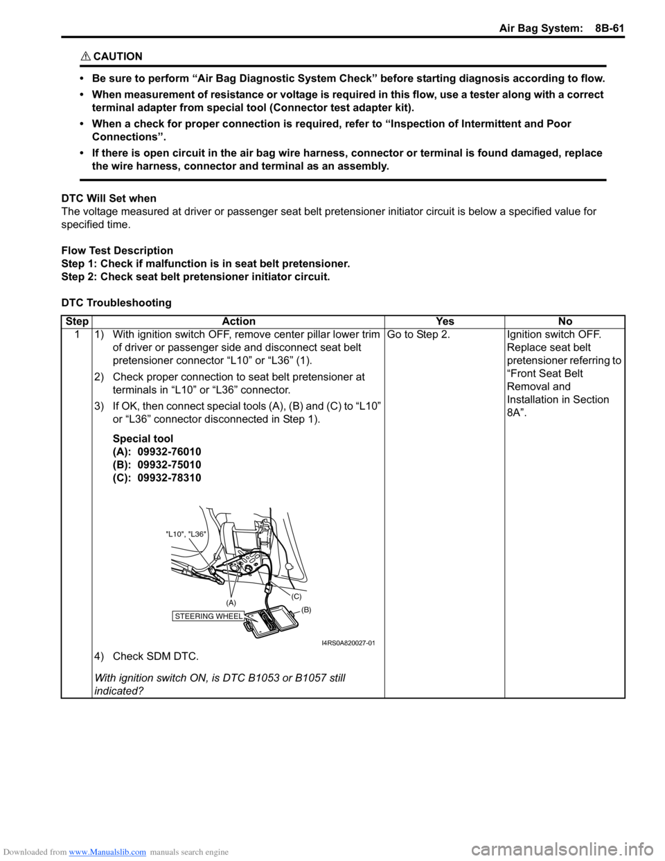
3) If OK, then connect special tools (A), (B) and (C) to “L10” or “L36” connector disconnected in Step 1).
Special tool
(A): 09932-76010
(B): 09932-75010
(C): 09932-78310
4) Check SDM DTC.
With ignition switch ON, is DTC B1053 or B1057 still
indicated? Go to Step 2.
Ignition switch OFF.
Replace seat belt
pretensioner referring to
“Front Seat Belt
Removal and
Installation in Section
8A”.
STEERING WHEEL(B)
(C)
(A)
"L10", "L36"
I4RS0A820027-01
Page 1101 of 1496
Downloaded from www.Manualslib.com manuals search engine Air Bag System: 8B-63
CAUTION!
• Be sure to perform “Air Bag Diagnostic System Check” before starting diagnosis according to flow.
• When measurement of resistance or voltage is required in this flow, use a tester along with a correct terminal adapter from special tool (Connector test adapter kit).
• When a check for proper connection is required, refer to “Inspection of Intermittent and Poor Connections”.
• If there is open circuit in the air bag wire harnes s, connector or terminal is found damaged, replace
the wire harness, connector and terminal as an assembly.
DTC Will Set when
The voltage measured at driver or passenger seat belt pr etensioner initiator circuit is above a specified value for
specified time.
Flow Test Description
Step 1: Check if malfunction is in seat belt pretensioner.
Step 2: Check seat belt pretensioner initiator circuit.
DTC Troubleshooting
Step Action YesNo
1 1) With ignition switch OFF, re move center pillar lower trim
of driver or passenger side and disconnect seat belt
pretensioner connector “L10” and “L36” (1).
2) Check proper connection to seat belt pretensioner at terminals in “L10” or “L36” connector.
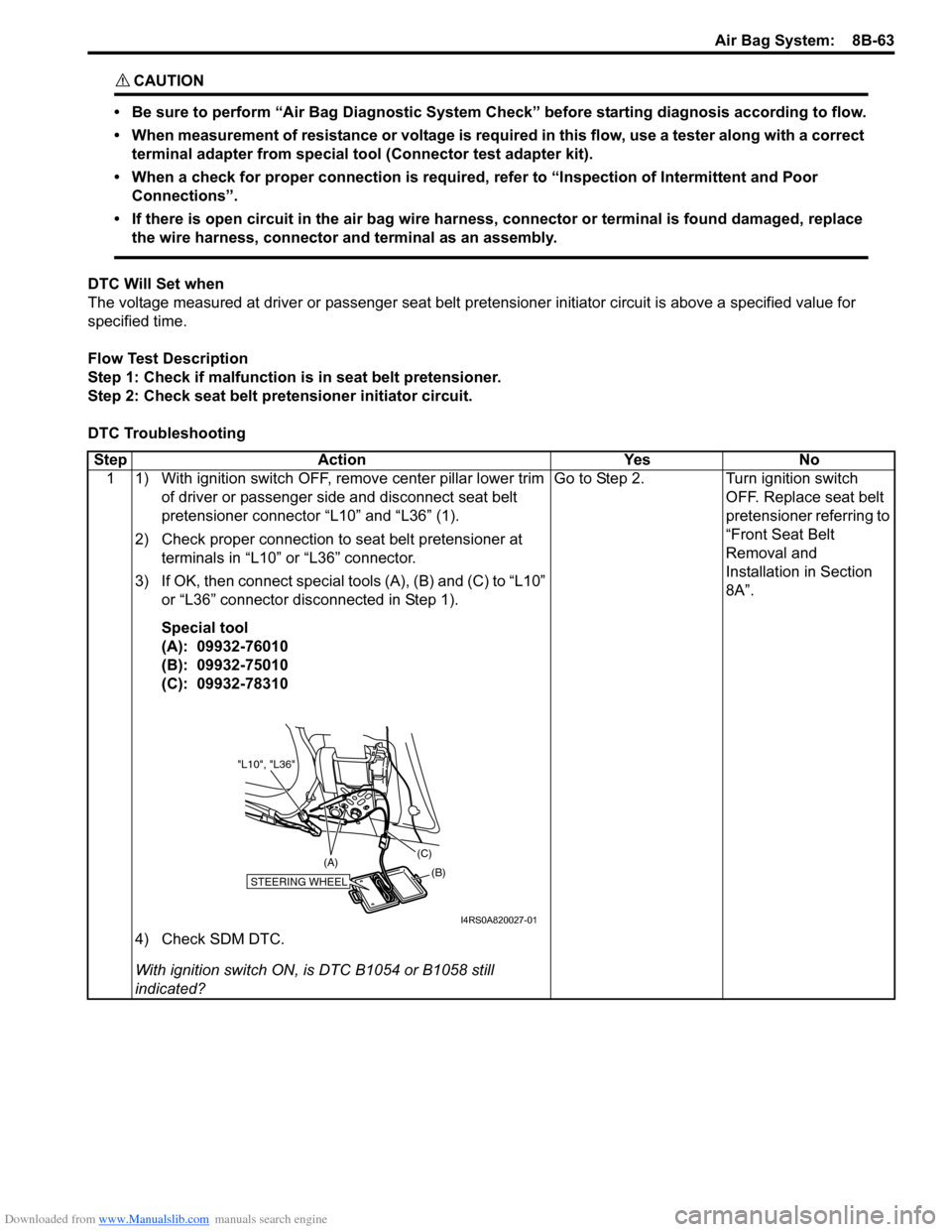
3) If OK, then connect special tools (A), (B) and (C) to “L10” or “L36” connector disconnected in Step 1).
Special tool
(A): 09932-76010
(B): 09932-75010
(C): 09932-78310
4) Check SDM DTC.
With ignition switch ON, is DTC B1054 or B1058 still
indicated? Go to Step 2.
Turn ignition switch
OFF. Replace seat belt
pretensioner referring to
“Front Seat Belt
Removal and
Installation in Section
8A”.
STEERING WHEEL(B)
(C)
(A)
"L10", "L36"
I4RS0A820027-01
Page 1148 of 1496
Downloaded from www.Manualslib.com manuals search engine 8B-110 Air Bag System:
Installation
CAUTION!
Proper operation of forward-sensor requires
sensor be rigidly attached to vehicle
structure and that the arrow on sensor be
pointing toward the front of the vehicle.
1) Check that none of the following faulty conditions exists.
• Bend, deformity or rust of front panel.
• Foreign matter on mating surface of sensor.
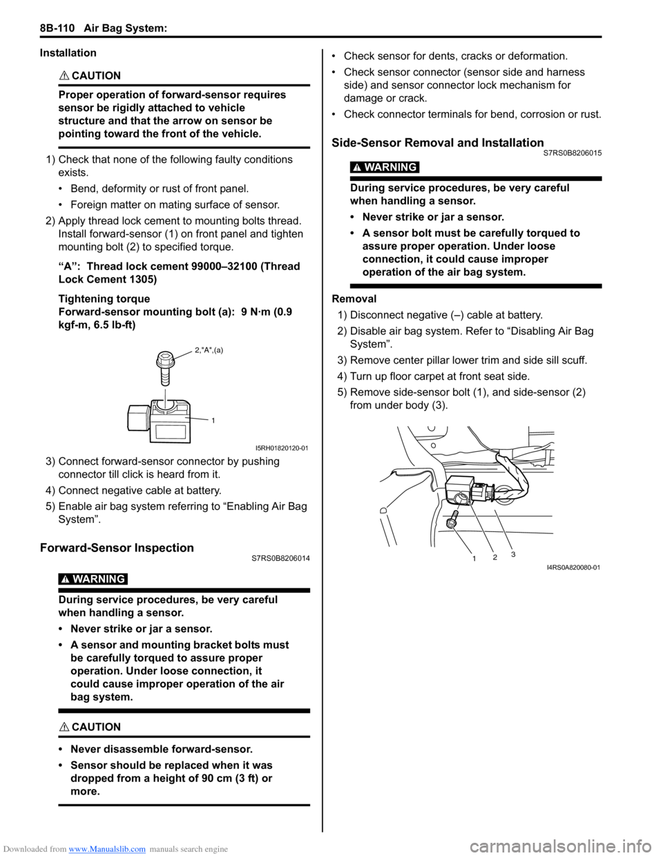
2) Apply thread lock cement to mounting bolts thread. Install forward-sensor (1) on front panel and tighten
mounting bolt (2) to specified torque.
“A”: Thread lock cement 99000–32100 (Thread
Lock Cement 1305)
Tightening torque
Forward-sensor mounting bolt (a): 9 N·m (0.9
kgf-m, 6.5 lb-ft)
3) Connect forward-sensor connector by pushing connector till click is heard from it.
4) Connect negative cable at battery.
5) Enable air bag system referring to “Enabling Air Bag System”.
Forward-Sensor InspectionS7RS0B8206014
WARNING!
During service procedures, be very careful
when handling a sensor.
• Never strike or jar a sensor.
• A sensor and mounting bracket bolts must be carefully torqued to assure proper
operation. Under loose connection, it
could cause improper operation of the air
bag system.
CAUTION!
• Never disassemble forward-sensor.
• Sensor should be replaced when it was dropped from a height of 90 cm (3 ft) or
more.
• Check sensor for dents, cracks or deformation.
• Check sensor connector (sensor side and harness side) and sensor connector lock mechanism for
damage or crack.
• Check connector terminals for bend, corrosion or rust.
Side-Sensor Removal and InstallationS7RS0B8206015
WARNING!
During service procedures, be very careful
when handling a sensor.
• Never strike or jar a sensor.
• A sensor bolt must be carefully torqued to assure proper operation. Under loose
connection, it could cause improper
operation of the air bag system.
Removal
1) Disconnect negative (–) cable at battery.
2) Disable air bag system. Re fer to “Disabling Air Bag
System”.
3) Remove center pillar lowe r trim and side sill scuff.
4) Turn up floor carpet at front seat side.
5) Remove side-sensor bolt (1), and side-sensor (2) from under body (3).
2,"A",(a)
1
I5RH01820120-01
1 23I4RS0A820080-01