2006 SUZUKI SWIFT PID
[x] Cancel search: PIDPage 468 of 1496
Downloaded from www.Manualslib.com manuals search engine 2D-1 Wheels and Tires:
Suspension
Wheels and Tires
Precautions
Precaution for Emergency Flat Tire Repair KitS7RS0B2400001
WARNING!
Flat tire repair sealant including in kit is
harmful. Be sure to observe the following.
Otherwise, your health may be ruined.
• If swallowed, get medical attention immediately.
• Keep out of reach of children.
• Select place where there is good ventilation for this work.
• If it enters eye or contacts skin, wash thoroughly with water. If anything
abnormal still rema ins, get medical
attention immediately.
• Do not discard tire containing sealant as it is. Make sure to remove sealant from tire,
referring to “Tire Repair for Emergency
Repaired-Tire with Sealant”.
• Dispose of sealant as waste oil.
CAUTION!
• When tire repaired with Emergency Flat Tire Repair Kit is brought in, remove flat
tire repair sealant from tire and repair flat
tire referring to “Tire Repair for Emergency
Repaired-Tire with Sealant”.
• Sealant expiration date is printed on bottle label. if it expires, sealant should be
replaced with a new one to ensure
emergency flat tire repair.
General Description
Tires DescriptionS7RS0B2401001
The tire is of tubeless type. The tire is designed to
operate satisfactorily with loads up to the full rated load
capacity when inflated to the recommended inflation
pressures.
Correct tire pressures and driving habits have an
important influence on tire life. Heavy cornering,
excessively rapid acceleration, and unnecessary sharp
braking increase tire wear.
Tire Placard
The “Tire Placard” is located on the left or right door lock
pillar and should be referred to tire information.
The placard lists the maximum load, tire size and cold
tire pressure where applicable.
NOTE
Whether rim size and/or maximum load are
listed or not depends on regulations of each
country.
Inflation of Tires
The pressure recommended for any model is carefully
calculated to give a satisfacto ry ride, stability, steering,
tread wear, tire life and resistance to bruises.
Tire pressure, with tires cold, (after vehicle has set for 3
hours or more, or driven less than one mile) should be
checked monthly or before any extended trip. Set to the
specifications on the “Tire Placard” located on the left
door lock pillar.
It is normal for tire pressure to increase when the tires
become hot during driving.
Do not bleed or reduce tire pressure after driving.
Bleeding reduces the “Cold Inflation Pressure”.
Higher than recommended pressure can cause:
• Hard ride
• Tire bruising or carcass damage
• Rapid tread wear at center of tire
Unequal pressure on same axle can cause:
• Uneven braking
• Steering lead
• Reduced handling
• Swerve on acceleration
Page 469 of 1496

Downloaded from www.Manualslib.com manuals search engine Wheels and Tires: 2D-2
Lower than recommended pressure can cause:
• Tire squeal on turns
• Hard Steering
• Rapid and uneven wear on the edges of the tread
• Tire rim bruises and rupture
• Tire cord breakage
• High tire temperature
• Reduced handling
• High fuel consumption
Replacement Tires
When replacement is necessary, the original equipment
type tire should be used. Refer to the Tire Placard.
Replacement tires should be of the same size, load
range and construction as those originally on the vehicle.
Use of any other size or type tire may affect ride,
handling, speedometer / odometer calibration, vehicle
ground clearance and tire or snow chain clearance to the
body and chassis.
It is recommended that new tires be installed in pairs on
the same axle. If necessary to replace only one tire, it
should be paired with the tire having the most tread, to
equalize braking traction.
WARNING!
Do not mix different types of tires on the
same vehicle such as radial, bias and bias-
belted tires except in emergencies, because
handling may be seriously affected and may
result in loss of control.
The metric term for tire infl ation pressure is the kilo
pascal (kPa). Tire pressures is usually printed in both
kPa and kgf/cm
2 on the “Tire Placard”.
Metric tire gauges are available from tool suppliers.
The chart, shown the table, converts commonly used
inflation pressures from kPa to kgf/cm
2 and psi.
Wheels DescriptionS7RS0B2401002
Wheel Maintenance
Wheel repairs that use welding, heating, or peening are
not approved. All damaged wheels should be replaced.
Replacement Wheels
Wheels must be replaced if they are bent, dented, have
excessive lateral or radial runout, air leak through welds,
have elongated bolt holes, if lug wheel bolts won’t stay
tight, or if they are heavily rusted. Wheels with greater
runout than shown in the following may cause
objectional vibrations.
Replacement wheels must be equivalent to the original
equipment wheels in load capacity, diameter, rim with
offset and mounting configuration. A wheel of improper
size or type may affect wheel and bearing life, brake
cooling, speedometer / odometer calibration, vehicle
ground clearance and tire clearance to body and
chassis.
How to Measure Wheel Runout
To measure the wheel runout, it is necessary to use an
accurate dial indicator. The tire may be on or off the
wheel. The wheel should be installed to the wheel
balancer of the like for proper measurement.
Take measurements of both lateral runout “a” and radial
runout “b” at both inside an d outside of the rim flange.
With the dial indicator set in place securely, turn the
wheel one full revolution slowly and record every reading
of the indicator.
When the measured runout exceeds the specification
and correction by the balancer adjustment is impossible,
replace the wheel. If the reading is affected by welding,
paint or scratch, it should be ignored.
Lateral runout limit “a”
: 0.3 mm (0.012 in.)
Radial runout limit “b”
: 0.3 mm (0.012 in.)
kPa kgf/cm2psi
Conversion: 1 psi =
6.895 kPa 1 kgf/cm
2 =
98.066 kPa 160 1.6 23
180 1.8 26
200 2.0 29
220 2.2 32
240 2.4 35
260 2.6 38
280 2.8 41
300 3.0 44
I4RS0A240001-01
Page 482 of 1496
Downloaded from www.Manualslib.com manuals search engine 3A-4 Drive Shaft / Axle:
Front Drive Shaft Assembly On-Vehicle
Inspection
S7RS0B3106002
• Check boots for breakage or deterioration.
• Check wheel side joint for rattle or smooth rotation.
• Check differential side (or center shaft side) joint for smooth rotation.
If any abnormality is found, replace.
Front Drive Shaft Assembly Removal and
Installation
S7RS0B3106003
Removal
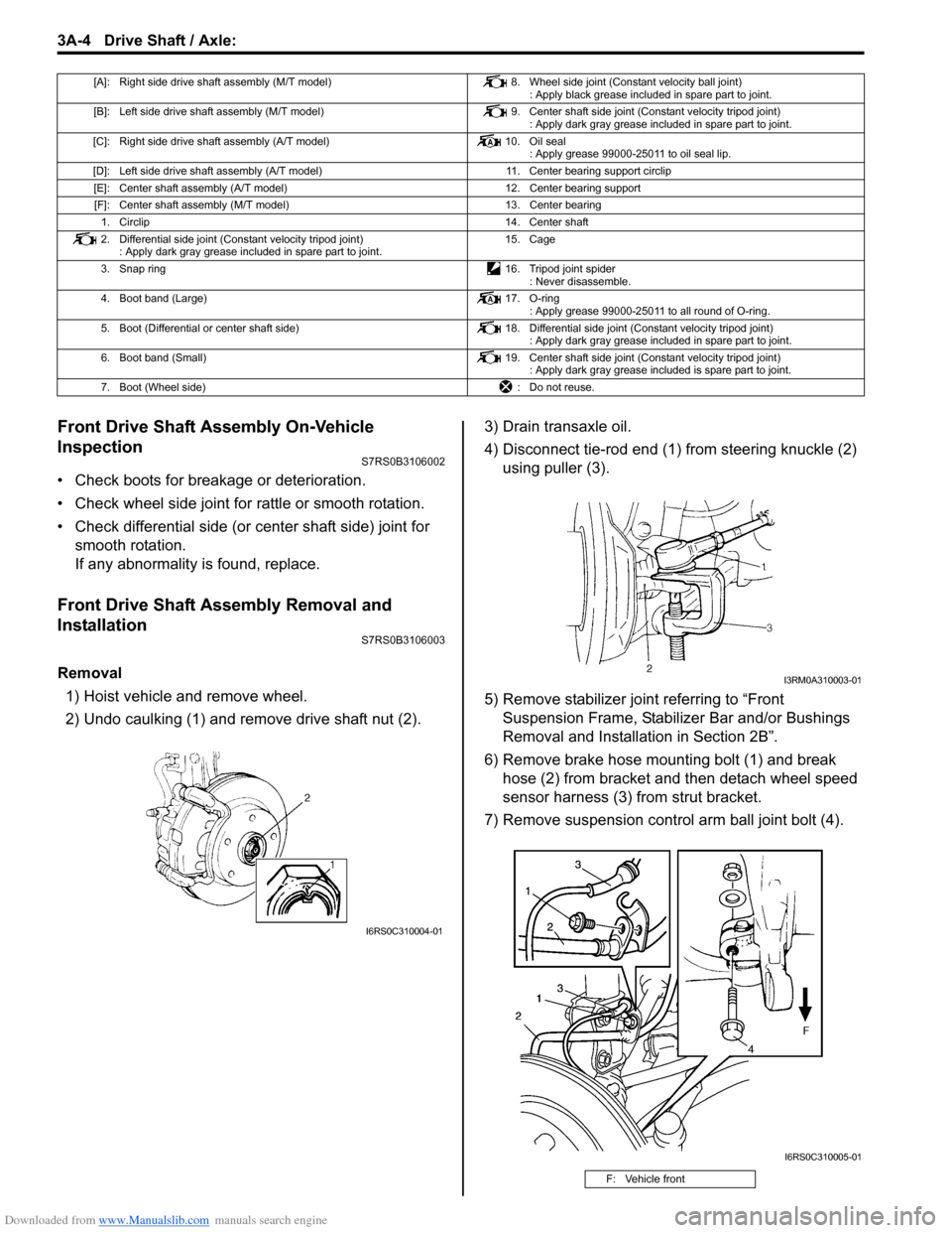
1) Hoist vehicle and remove wheel.
2) Undo caulking (1) and remove drive shaft nut (2). 3) Drain transaxle oil.
4) Disconnect tie-rod end (1) from steering knuckle (2)
using puller (3).
5) Remove stabilizer join t referring to “Front
Suspension Frame, Stabiliz er Bar and/or Bushings
Removal and Installati on in Section 2B”.
6) Remove brake hose mounting bolt (1) and break hose (2) from bracket and then detach wheel speed
sensor harness (3) from strut bracket.
7) Remove suspension contro l arm ball joint bolt (4).
[A]: Right side drive shaft assembly (M/T model) 8. Wheel side joint (Constant velocity ball joint)
: Apply black grease included in spare part to joint.
[B]: Left side drive shaft assembly (M/T model) 9. Center shaft side joint (Constant velocity tripod joint)
: Apply dark gray grease included in spare part to joint.
[C]: Right side drive shaft assembly (A/T model) 10. Oil seal
: Apply grease 99000-25011 to oil seal lip.
[D]: Left side drive shaft assembly (A/T model) 11. Center bearing support circlip
[E]: Center shaft assembly (A/T model) 12. Center bearing support
[F]: Center shaft assembly (M/T model) 13. Center bearing
1. Circlip 14. Center shaft
2. Differential side joint (Constant velocity tripod joint) : Apply dark gray grease included in spare part to joint. 15. Cage
3. Snap ring 16. Tripod joint spider
: Never disassemble.
4. Boot band (Large) 17. O-ring
: Apply grease 99000-25011 to all round of O-ring.
5. Boot (Differential or center shaft side) 18. Differential side joint (Constant velocity tripod joint)
: Apply dark gray grease included in spare part to joint.
6. Boot band (Small) 19. Center shaft side joint (Constant velocity tripod joint)
: Apply dark gray grease included is spare part to joint.
7. Boot (Wheel side) : Do not reuse.
I6RS0C310004-01
F: Vehicle front
I3RM0A310003-01
I6RS0C310005-01
Page 484 of 1496
Downloaded from www.Manualslib.com manuals search engine 3A-6 Drive Shaft / Axle:
Front Drive Shaft Disassembly and ReassemblyS7RS0B3106004
Disassembly
Tripod joint
CAUTION!
• Disassembly of wheel side joint is not allowed. If any noise or damage exists in it,
replace it as assembly.
• Do not disassemble tripod joint spider. If any malcondition is found in it, replace it
as differential side joint assembly.
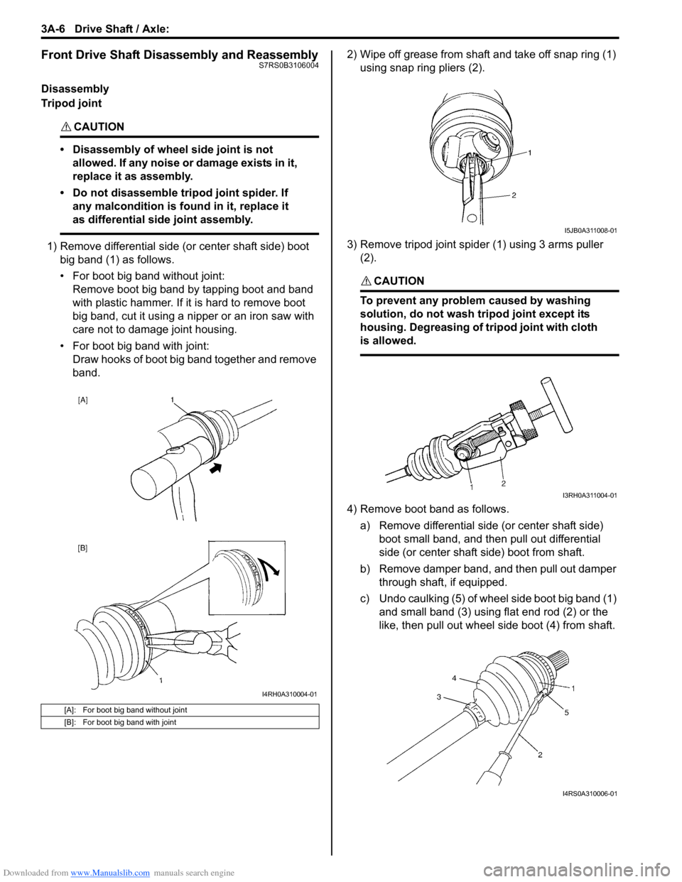
1) Remove differential side (or center shaft side) boot
big band (1) as follows.
• For boot big band without joint:Remove boot big band by tapping boot and band
with plastic hammer. If it is hard to remove boot
big band, cut it using a nipper or an iron saw with
care not to damage joint housing.
• For boot big band with joint: Draw hooks of boot big band together and remove
band. 2) Wipe off grease from shaft and take off snap ring (1)
using snap ring pliers (2).
3) Remove tripod joint spid er (1) using 3 arms puller
(2).
CAUTION!
To prevent any problem caused by washing
solution, do not wash tripod joint except its
housing. Degreasing of tr ipod joint with cloth
is allowed.
4) Remove boot band as follows.
a) Remove differential side (or center shaft side) boot small band, and then pull out differential
side (or center shaft side) boot from shaft.
b) Remove damper band, and then pull out damper through shaft, if equipped.
c) Undo caulking (5) of wheel side boot big band (1) and small band (3) using flat end rod (2) or the
like, then pull out wheel side boot (4) from shaft.
[A]: For boot big band without joint
[B]: For boot big band with joint
I4RH0A310004-01
I5JB0A311008-01
I3RH0A311004-01
I4RS0A310006-01
Page 487 of 1496
Downloaded from www.Manualslib.com manuals search engine Drive Shaft / Axle: 3A-9
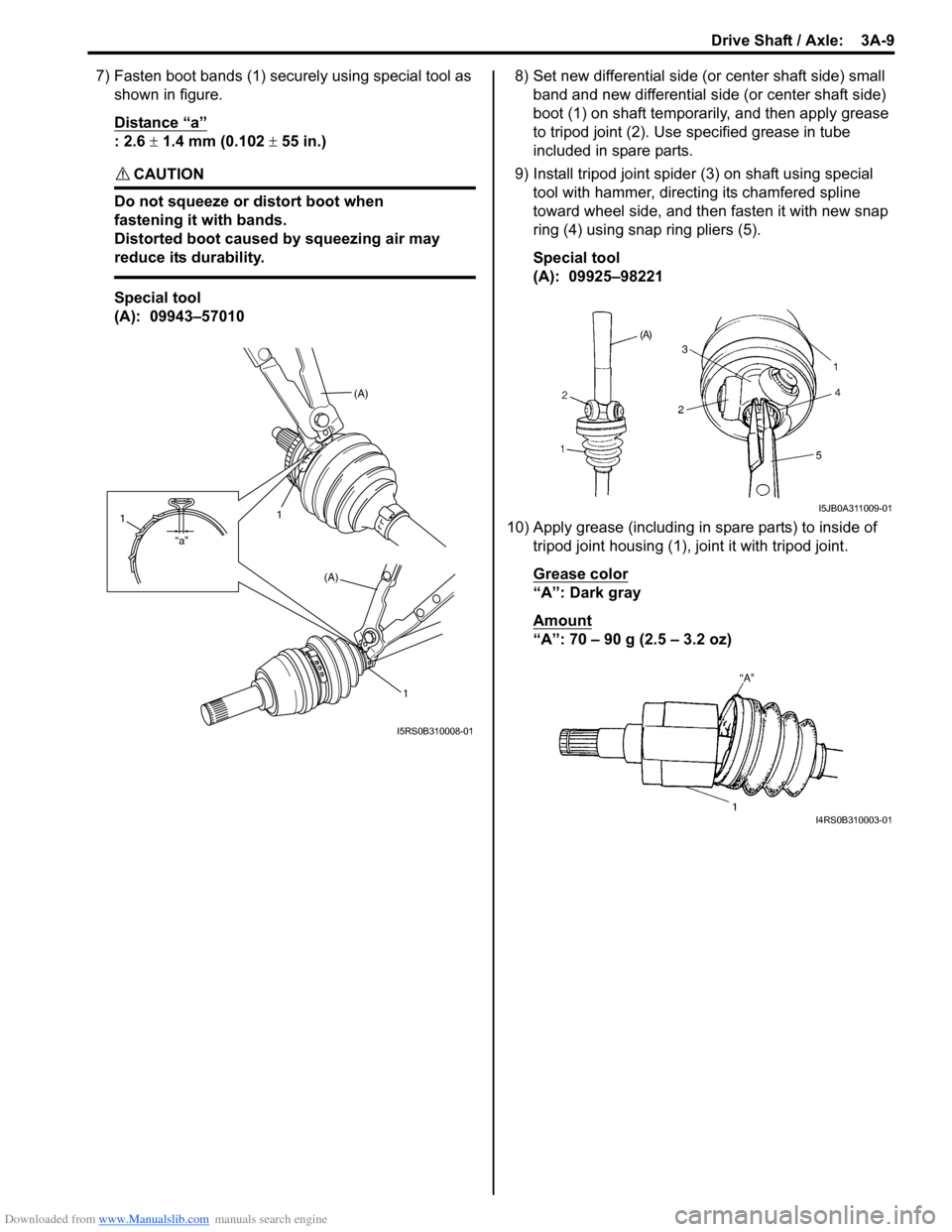
7) Fasten boot bands (1) securely using special tool as
shown in figure.
Distance “a”
: 2.6 ± 1.4 mm (0.102 ± 55 in.)
CAUTION!
Do not squeeze or distort boot when
fastening it with bands.
Distorted boot caused by squeezing air may
reduce its durability.
Special tool
(A): 09943–57010 8) Set new differential side (or center shaft side) small
band and new differential side (or center shaft side)
boot (1) on shaft temporarily, and then apply grease
to tripod joint (2). Use specified grease in tube
included in spare parts.
9) Install tripod joint spider (3) on shaft using special
tool with hammer, directing its chamfered spline
toward wheel side, and then fasten it with new snap
ring (4) using snap ring pliers (5).
Special tool
(A): 09925–98221
10) Apply grease (including in spare parts) to inside of tripod joint housing (1), jo int it with tripod joint.
Grease color
“A”: Dark gray
Amount
“A”: 70 – 90 g (2.5 – 3.2 oz)
(A)
1
(A)
1
“a”
1
I5RS0B310008-01
I5JB0A311009-01
I4RS0B310003-01
Page 1040 of 1496
Downloaded from www.Manualslib.com manuals search engine 8B-2 Air Bag System:
Precautions on Handling and Storage of Air Bag
System Components
S7RS0B8200002
SDM
WARNING!
Never power up air bag system when SDM is
not rigidly attached to the vehicle. Otherwise,
personal injury may result.
CAUTION!
After detecting one time of such collision as
to meet deployment conditions, SDM must
not be used. Refer to “Air Bag Diagnostic
System Check” when checking SDM.
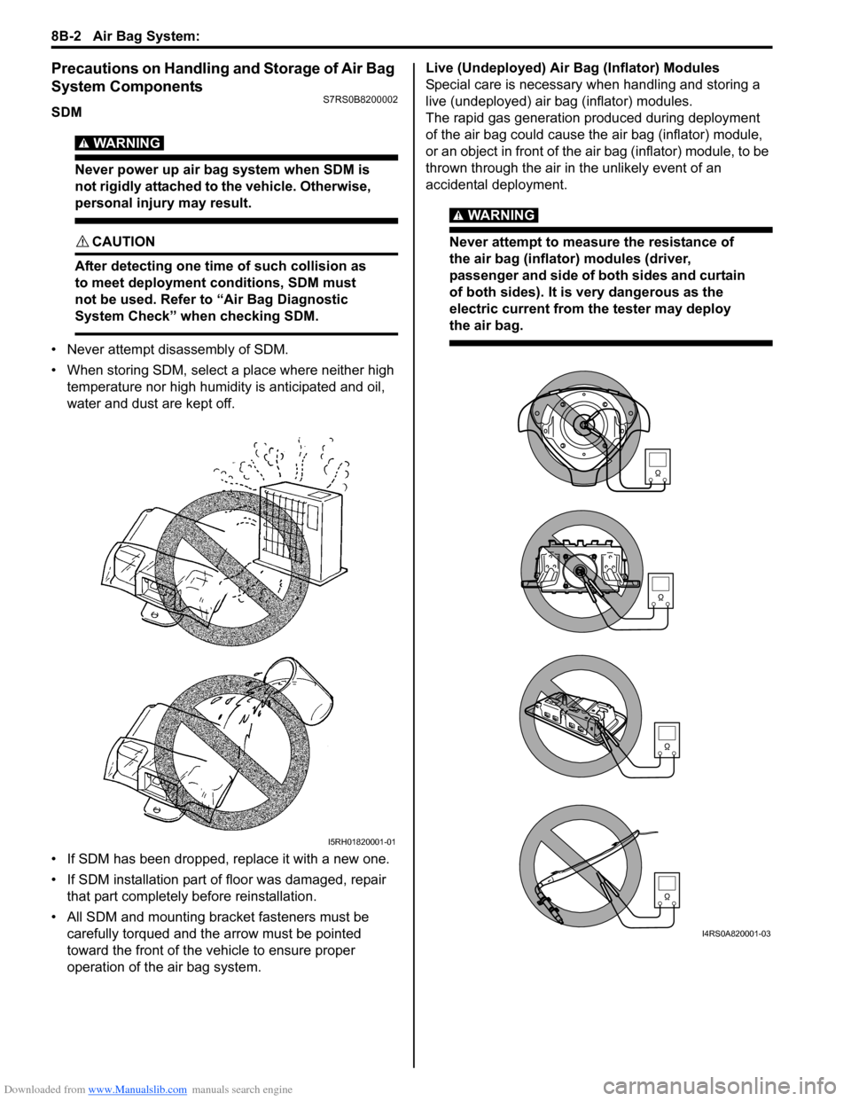
• Never attempt disassembly of SDM.
• When storing SDM, select a place where neither high temperature nor high humidity is anticipated and oil,
water and dust are kept off.
• If SDM has been dropped, replace it with a new one.
• If SDM installation part of floor was damaged, repair that part completely before reinstallation.
• All SDM and mounting bracket fasteners must be carefully torqued and the arrow must be pointed
toward the front of the vehicle to ensure proper
operation of the air bag system. Live (Undeployed) Air Bag (Inflator) Modules
Special care is necessary when handling and storing a
live (undeployed) air bag (inflator) modules.
The rapid gas generation produced during deployment
of the air bag could cause the air bag (inflator) module,
or an object in front of the air bag (inflator) module, to be
thrown through the air in the unlikely event of an
accidental deployment.
WARNING!
Never attempt to measure the resistance of
the air bag (inflator) modules (driver,
passenger and side of both sides and curtain
of both sides). It is
very dangerous as the
electric current from the tester may deploy
the air bag.
I5RH01820001-01
I4RS0A820001-03
Page 1157 of 1496
Downloaded from www.Manualslib.com manuals search engine Air Bag System: 8B-119
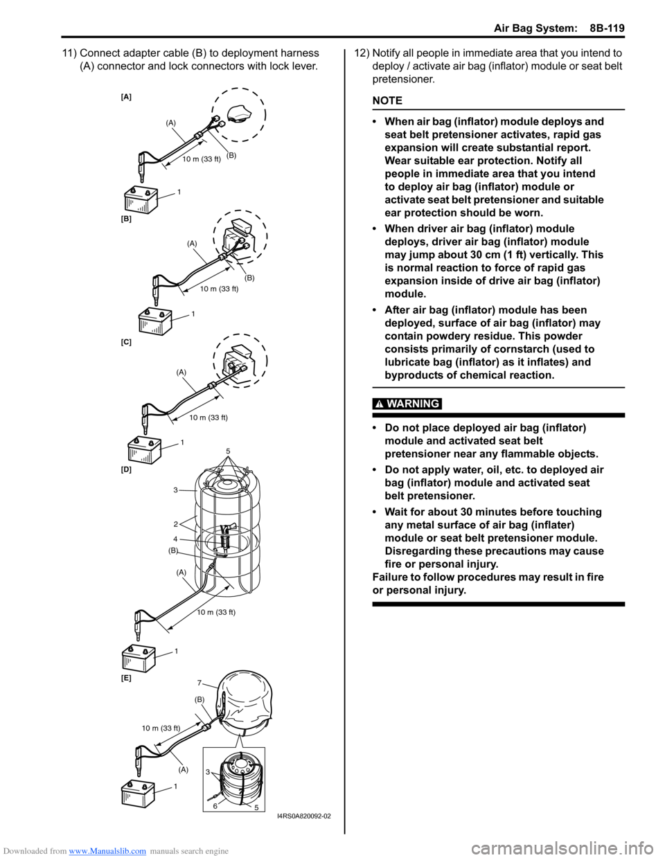
11) Connect adapter cable (B) to deployment harness (A) connector and lock connectors with lock lever. 12) Notify all people in immediate area that you intend to
deploy / activate air bag (inflator) module or seat belt
pretensioner.
NOTE
• When air bag (inflator) module deploys and seat belt pretensioner activates, rapid gas
expansion will create substantial report.
Wear suitable ear protection. Notify all
people in immediate area that you intend
to deploy air bag (inflator) module or
activate seat belt pretensioner and suitable
ear protection should be worn.
• When driver air bag (inflator) module deploys, driver air bag (inflator) module
may jump about 30 cm (1 ft) vertically. This
is normal reaction to force of rapid gas
expansion inside of drive air bag (inflator)
module.
• After air bag (inflator) module has been deployed, surface of air bag (inflator) may
contain powdery residue. This powder
consists primarily of cornstarch (used to
lubricate bag (inflator) as it inflates) and
byproducts of chemical reaction.
WARNING!
• Do not place deployed air bag (inflator) module and activated seat belt
pretensioner near any flammable objects.
• Do not apply water, oil, etc. to deployed air bag (inflator) module and activated seat
belt pretensioner.
• Wait for about 30 minutes before touching any metal surface of air bag (inflater)
module or seat belt pretensioner module.
Disregarding these precautions may cause
fire or personal injury.
Failure to follow procedures may result in fire
or personal injury.
[A]
10 m (33 ft)
(A)
(B)
1
10 m (33 ft)
(A)
(B) 1
5
3 2
4
(A)
[B]
[C]
[D]
[E]
7
3
6 5
(A) (B)
1
10 m (33 ft)
10 m (33 ft)
(A)
(B)
1
1
10 m (33 ft)
I4RS0A820092-02
Page 1161 of 1496
Downloaded from www.Manualslib.com manuals search engine Air Bag System: 8B-123
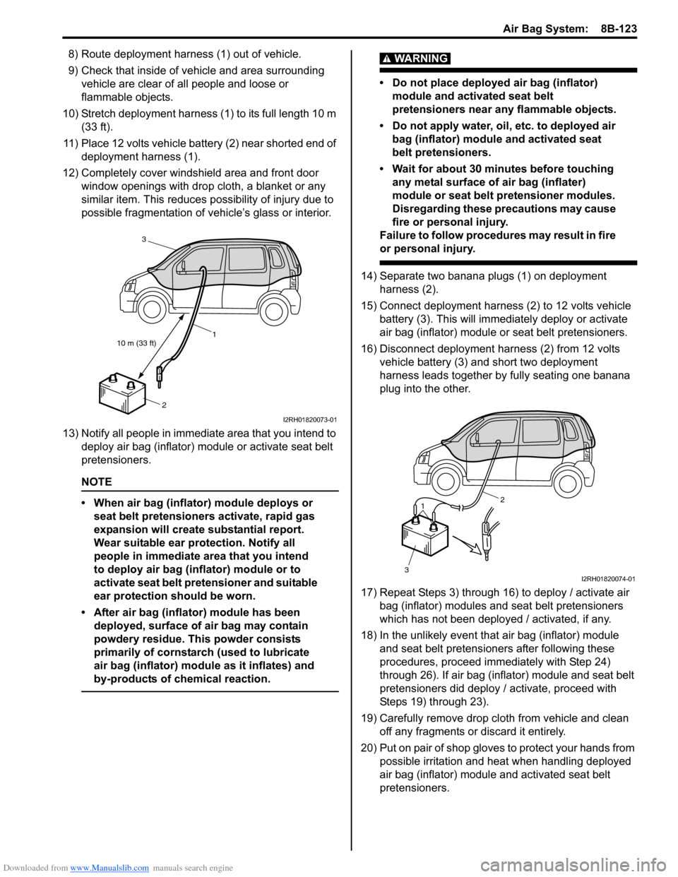
8) Route deployment harness (1) out of vehicle.
9) Check that inside of vehicle and area surrounding vehicle are clear of all people and loose or
flammable objects.
10) Stretch deployment harness (1) to its full length 10 m (33 ft).
11) Place 12 volts vehicle battery (2) near shorted end of deployment harness (1).
12) Completely cover windshield area and front door window openings with drop cloth, a blanket or any
similar item. This reduces possibility of injury due to
possible fragmentation of vehicle’s glass or interior.
13) Notify all people in immediate area that you intend to deploy air bag (inflator) module or activate seat belt
pretensioners.
NOTE
• When air bag (inflator) module deploys or seat belt pretensioners activate, rapid gas
expansion will create substantial report.
Wear suitable ear protection. Notify all
people in immediate area that you intend
to deploy air bag (inflator) module or to
activate seat belt pretensioner and suitable
ear protection should be worn.
• After air bag (inflator) module has been deployed, surface of air bag may contain
powdery residue. This powder consists
primarily of cornstarch (used to lubricate
air bag (inflator) module as it inflates) and
by-products of chemical reaction.
WARNING!
• Do not place deployed air bag (inflator) module and activated seat belt
pretensioners near any flammable objects.
• Do not apply water, oil, etc. to deployed air bag (inflator) module and activated seat
belt pretensioners.
• Wait for about 30 minutes before touching any metal surface of air bag (inflater)
module or seat belt pretensioner modules.
Disregarding these precautions may cause
fire or personal injury.
Failure to follow procedures may result in fire
or personal injury.
14) Separate two banana plugs (1) on deployment harness (2).
15) Connect deployment harness (2) to 12 volts vehicle battery (3). This will immedi ately deploy or activate
air bag (inflator) module or seat belt pretensioners.
16) Disconnect deployment harness (2) from 12 volts vehicle battery (3) and short two deployment
harness leads together by fully seating one banana
plug into the other.
17) Repeat Steps 3) through 16) to deploy / activate air bag (inflator) modules and seat belt pretensioners
which has not been deployed / activated, if any.
18) In the unlikely event that air bag (inflator) module and seat belt pretensioners after following these
procedures, proceed immediately with Step 24)
through 26). If air bag (inflator) module and seat belt
pretensioners did deploy / activate, proceed with
Steps 19) through 23).
19) Carefully remove drop cloth from vehicle and clean off any fragments or discard it entirely.
20) Put on pair of shop gloves to protect your hands from
possible irritation and heat when handling deployed
air bag (inflator) module and activated seat belt
pretensioners.
10 m (33 ft) 1
2
3
I2RH01820073-01
1
3 2
I2RH01820074-01