Page 841 of 1496

Downloaded from www.Manualslib.com manuals search engine Manual Transmission/Transaxle: 5B-27
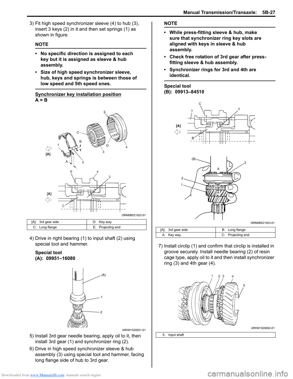
3) Fit high speed synchronizer sleeve (4) to hub (3), insert 3 keys (2) in it and then set springs (1) as
shown in figure.
NOTE
• No specific direction is assigned to each key but it is assigned as sleeve & hub
assembly.
• Size of high speed synchronizer sleeve, hub, keys and springs is between those of
low speed and 5th speed ones.
Synchronizer key in stallation position
A = B
4) Drive in right bearing (1) to input shaft (2) using special tool and hammer.
Special tool
(A): 09951–16080
5) Install 3rd gear needle bearing, apply oil to it, then install 3rd gear (1) and synchronizer ring (2).
6) Drive in high speed synchronizer sleeve & hub assembly (3) using special tool and hammer, facing
long flange side of hub to 3rd gear.
NOTE
• While press-fitting sleeve & hub, make sure that synchronizer ring key slots are
aligned with keys in sleeve & hub
assembly.
• Check free rotation of 3rd gear after press- fitting sleeve & hub assembly.
• Synchronizer rings for 3rd and 4th are identical.
Special tool
(B): 09913–84510
7) Install circlip (1) and confirm that circlip is installed in
groove securely. Install needle bearing (2) of resin
cage type, apply oil to it and then install synchronizer
ring (3) and 4th gear (4).
[A]: 3rd gear side D: Key way
C: Long flange E: Projecting end
I3RM0B521022-01
(A)
1
2
I4RH01520031-01
[A]: 3rd gear side B: Long flange
A: Key way C: Projecting end
5. Input shaft
I3RM0B521023-01
I2RH01520052-01
Page 843 of 1496

Downloaded from www.Manualslib.com manuals search engine Manual Transmission/Transaxle: 5B-29
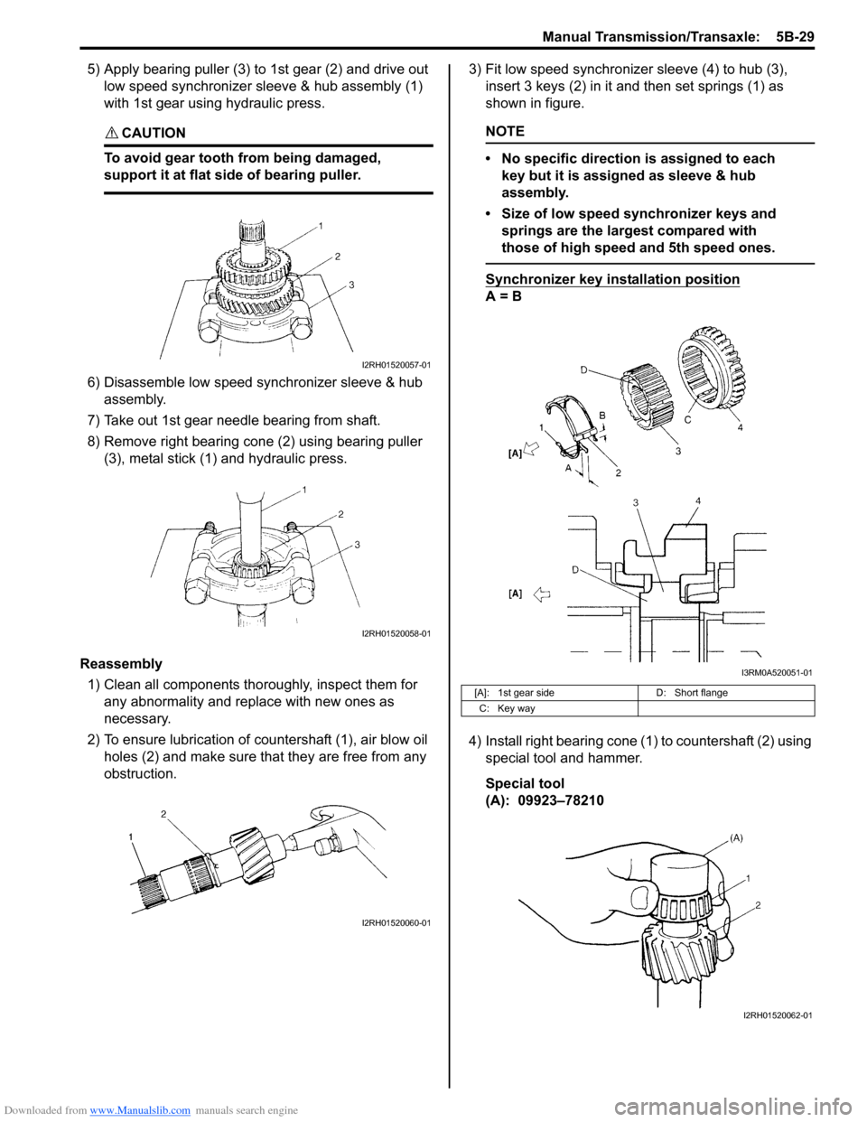
5) Apply bearing puller (3) to 1st gear (2) and drive out low speed synchronizer sleeve & hub assembly (1)
with 1st gear using hydraulic press.
CAUTION!
To avoid gear tooth from being damaged,
support it at flat side of bearing puller.
6) Disassemble low speed synchronizer sleeve & hub assembly.
7) Take out 1st gear needle bearing from shaft.
8) Remove right bearing cone (2) using bearing puller (3), metal stick (1) and hydraulic press.
Reassembly 1) Clean all components thor oughly, inspect them for
any abnormality and replace with new ones as
necessary.
2) To ensure lubrication of countershaft (1), air blow oil holes (2) and make sure that they are free from any
obstruction. 3) Fit low speed synchronizer sleeve (4) to hub (3),
insert 3 keys (2) in it and then set springs (1) as
shown in figure.
NOTE
• No specific direction is assigned to each key but it is assigned as sleeve & hub
assembly.
• Size of low speed synchronizer keys and springs are the largest compared with
those of high speed and 5th speed ones.
Synchronizer key installation position
A = B
4) Install right bearing cone (1) to countershaft (2) using special tool and hammer.
Special tool
(A): 09923–78210
I2RH01520057-01
I2RH01520058-01
I2RH01520060-01
[A]: 1st gear side D: Short flange
C: Key way
I3RM0A520051-01
I2RH01520062-01
Page 844 of 1496

Downloaded from www.Manualslib.com manuals search engine 5B-30 Manual Transmission/Transaxle:
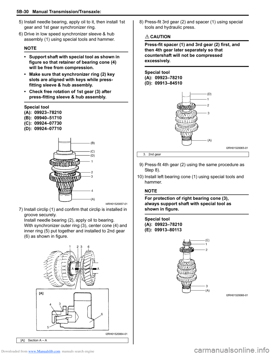
5) Install needle bearing, apply oil to it, then install 1st gear and 1st gear synchronizer ring.
6) Drive in low speed synchronizer sleeve & hub assembly (1) using special tools and hammer.
NOTE
• Support shaft with special tool as shown in figure so that retainer of bearing cone (4)
will be free from compression.
• Make sure that synchronizer ring (2) key slots are aligned with keys while press-
fitting sleeve & hub assembly.
• Check free rotation of 1st gear (3) after press-fitting sleeve & hub assembly.
Special tool
(A): 09923–78210
(B): 09940–51710
(C): 09924–07730
(D): 09924–07710
7) Install circlip (1) and confirm that circlip is installed in groove securely.
Install needle bearing (2), apply oil to bearing.
With synchronizer outer ring (3), center cone (4) and
inner ring (5) put together and installed to 2nd gear
(6) as shown in figure. 8) Press-fit 3rd gear (2) and spacer (1) using special
tools and hydraulic press.
CAUTION!
Press-fit spacer (1) and 3rd gear (2) first, and
then 4th gear later separately so that
countershaft will not be compressed
excessively.
Special tool
(A): 09923–78210
(D): 09913–84510
9) Press-fit 4th gear (2) using the same procedure as Step 8).
10) Install left bearing cone (1) using special tools and hammer.
NOTE
For protection of right bearing cone (3),
always support shaft with special tool as
shown in figure.
Special tool
(A): 09923–78210
(E): 09913–80113
[A]: Section A – A
I4RH01520057-01
I2RH01520064-01
3. 2nd gear
I2RH01520065-01
I2RH01520066-01
Page 1461 of 1496

Downloaded from www.Manualslib.com manuals search engine Immobilizer Control System: 10C-18
Repair Instructions
Immobilizer Control Module (ICM) Removal and
Installation
S7RS0BA306001
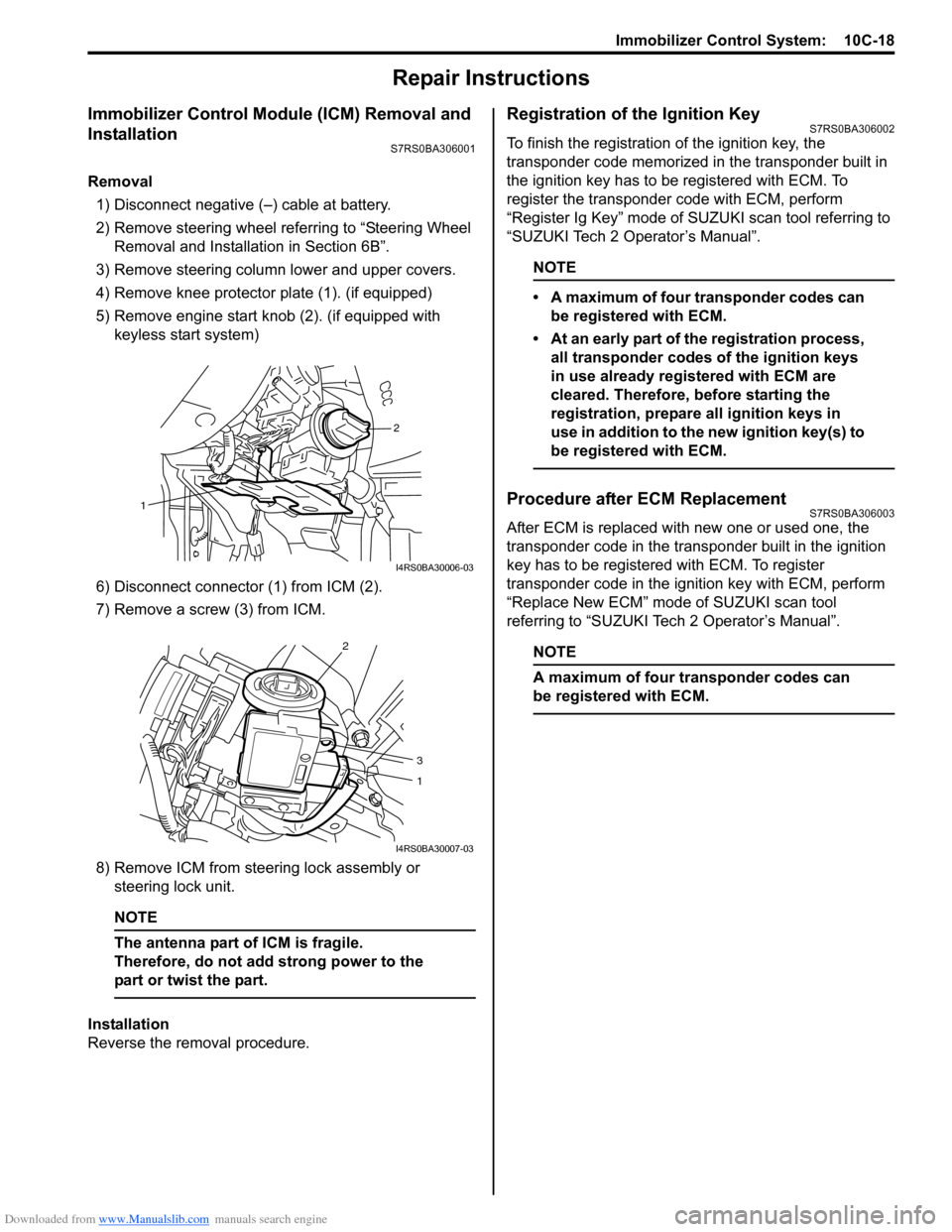
Removal1) Disconnect negative (–) cable at battery.
2) Remove steering wheel referring to “Steering Wheel Removal and Installa tion in Section 6B”.
3) Remove steering column lower and upper covers.
4) Remove knee protector plate (1). (if equipped)
5) Remove engine start knob (2). (if equipped with keyless start system)
6) Disconnect connector (1) from ICM (2).
7) Remove a screw (3) from ICM.
8) Remove ICM from steering lock assembly or steering lock unit.
NOTE
The antenna part of ICM is fragile.
Therefore, do not add strong power to the
part or twist the part.
Installation
Reverse the removal procedure.
Registration of the Ignition KeyS7RS0BA306002
To finish the registration of the ignition key, the
transponder code memorized in the transponder built in
the ignition key has to be registered with ECM. To
register the transponder code with ECM, perform
“Register Ig Key” mode of SU ZUKI scan tool referring to
“SUZUKI Tech 2 Operator’s Manual”.
NOTE
• A maximum of four transponder codes can be registered with ECM.
• At an early part of the registration process, all transponder codes of the ignition keys
in use already registered with ECM are
cleared. Therefore, before starting the
registration, prepare all ignition keys in
use in addition to the new ignition key(s) to
be registered with ECM.
Procedure after ECM ReplacementS7RS0BA306003
After ECM is replaced with new one or used one, the
transponder code in the transponder built in the ignition
key has to be registered with ECM. To register
transponder code in the ignition key with ECM, perform
“Replace New ECM” mode of SUZUKI scan tool
referring to “SUZUKI Tech 2 Operator’s Manual”.
NOTE
A maximum of four transponder codes can
be registered with ECM.
2
1
I4RS0BA30006-03
2
3
1
I4RS0BA30007-03