Page 329 of 1496
Downloaded from www.Manualslib.com manuals search engine Engine Mechanical: 1D-44
Pistons, Piston Rings, Connecting Rods and Cylinders ComponentsS7RS0B1406029
1. Top ring 6. Connecting rod bearing cap : See “B”: Tighten15 N
⋅m (1.5 kgf-m, 11.0 lb-ft), 45 °
and 45 ° by the specified procedure.
2. 2nd ring 7. Connecting rod bearing : Apply engine oil to sliding surface of each
part.
3. Oil ring 8. Piston pin : Do not reuse.
4. Piston 9. Piston pin circlip
5. Connecting rod : See “A” 10. Connecting rod bearing cap bolt
: See “C”
“A”: Apply engine oil to sliding surface except inner surface of big end.
“B”: Point arrow mark on cap to crankshaft pulley side.
“C”: Make sure bearing cap bolt diameter when reuse it due to plastic deformation tightening. Refer to “Piston Pins and Connecti ng Rods Inspection”.
(a)1
2
3
9
4
5
6 10
7 8
9
OIL
OIL
OIL
OIL
OIL
OIL
OIL
OIL
OIL
I6RS0C140021-02
Page 331 of 1496

Downloaded from www.Manualslib.com manuals search engine Engine Mechanical: 1D-46
Pistons, Piston Rings, Connecting Rods and
Cylinders Disassembly and Assembly
S7RS0B1406031
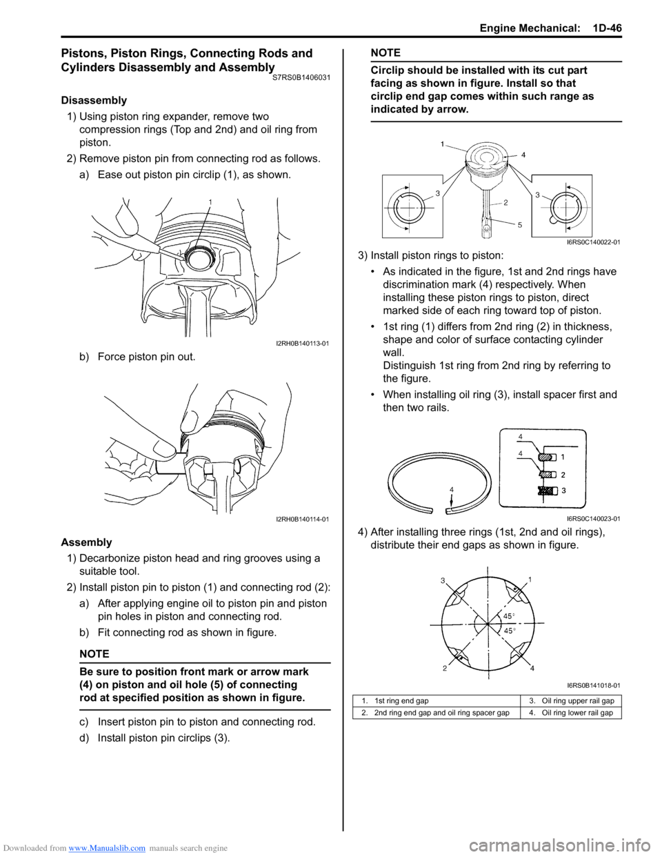
Disassembly1) Using piston ring expander, remove two compression rings (Top and 2nd) and oil ring from
piston.
2) Remove piston pin from connecting rod as follows. a) Ease out piston pin circlip (1), as shown.
b) Force piston pin out.
Assembly 1) Decarbonize piston head and ring grooves using a suitable tool.
2) Install piston pin to piston (1) and connecting rod (2): a) After applying engine oil to piston pin and piston pin holes in piston and connecting rod.
b) Fit connecting rod as shown in figure.
NOTE
Be sure to position front mark or arrow mark
(4) on piston and oil hole (5) of connecting
rod at specified position as shown in figure.
c) Insert piston pin to piston and connecting rod.
d) Install piston pin circlips (3).
NOTE
Circlip should be installed with its cut part
facing as shown in figure. Install so that
circlip end gap comes within such range as
indicated by arrow.
3) Install piston rings to piston:
• As indicated in the figure, 1st and 2nd rings have discrimination mark (4) respectively. When
installing these piston rings to piston, direct
marked side of each ring toward top of piston.
• 1st ring (1) differs from 2nd ring (2) in thickness, shape and color of surface contacting cylinder
wall.
Distinguish 1st ring from 2nd ring by referring to
the figure.
• When installing oil ring (3), install spacer first and then two rails.
4) After installing three rings (1st, 2nd and oil rings), distribute their end gaps as shown in figure.
I2RH0B140113-01
I2RH0B140114-01
1. 1st ring end gap 3. Oil ring upper rail gap
2. 2nd ring end gap and oil ring spacer gap 4. Oil ring lower rail gap
I6RS0C140022-01
I6RS0C140023-01
I6RS0B141018-01
Page 360 of 1496
Downloaded from www.Manualslib.com manuals search engine 1E-8 Engine Lubrication System:
Oil Pump ComponentsS7RS0B1506007
Oil Pump Removal and InstallationS7RS0B1506008
Oil pump is incorporated with timing chain cover.
For removal and installation, refer to “Timing Chain
Cover Removal and Installation in Section 1D”.
Oil Pump Disassembly and ReassemblyS7RS0B1506009
Disassembly1) Remove rotor plate (1) by removing its mounting bolts. 2) Remove outer rotor (1) and inner rotor (2).
3) Remove relief valve (1), spring (2) and retainer (3) by
removing circlip (4).
I4RS0A150010-01
1. Rotor plate 6. Rotor plate bolt10. Circlip
2. O-ring 7. Relief valve : 11 N⋅m (1.1 kgf-mm 8.0 lb-ft)
3. Outer rotor 8. Spring : Do not reuse.
4. Inner rotor 9. Retainer : Apply thin coat of engine oil to sliding surface.
5. Timing chain cover 10. Circlip
I2RH0B150018-01
I2RH0B150019-01
I2RH0B150020-01
Page 361 of 1496

Downloaded from www.Manualslib.com manuals search engine Engine Lubrication System: 1E-9
Reassembly1) Wash, clean and then dry all disassembled parts.
2) Apply thin coat of engine oil to inner and outer rotors, oil seal lip portion, inside surfaces of oil pump case
and plate.
3) Install outer (1) and inner rotors (2) to oil pump case.
4) Apply engine oil to relief valve (1) and spring (2), and install them with retainer (3) and new circlip (4) to
rotor plate (5).
5) Install rotor plate and tighten all bolts to specified torque. After installing plate, check to be sure that
rotors turn smoothly by hand (0.3 N ⋅m (0.03 kgf-m,
0.25 lb-ft) torque or below).
Tightening torque
Oil pump rotor plate bolt (a): 11 N·m (1.1 kgf-m,
8.0 lb-ft)Oil Pump InspectionS7RS0B1506010
Oil Seal
Check oil seal lip for fault or other damage. Replace as
necessary.
Oil Pump
• Check outer (1) and inner rotors (2), rotor plate, and oil pump case for excessive wear or damage.
• Check relief valve (1) for excessive wear or damage
and operates smoothly.
I2RH0B150019-01
I3RM0A150005-01
I2RH0B150022-01
I2RH0B150023-01
I2RH0B150019-01
I2RH0B150025-01
Page 441 of 1496

Downloaded from www.Manualslib.com manuals search engine Front Suspension: 2B-8
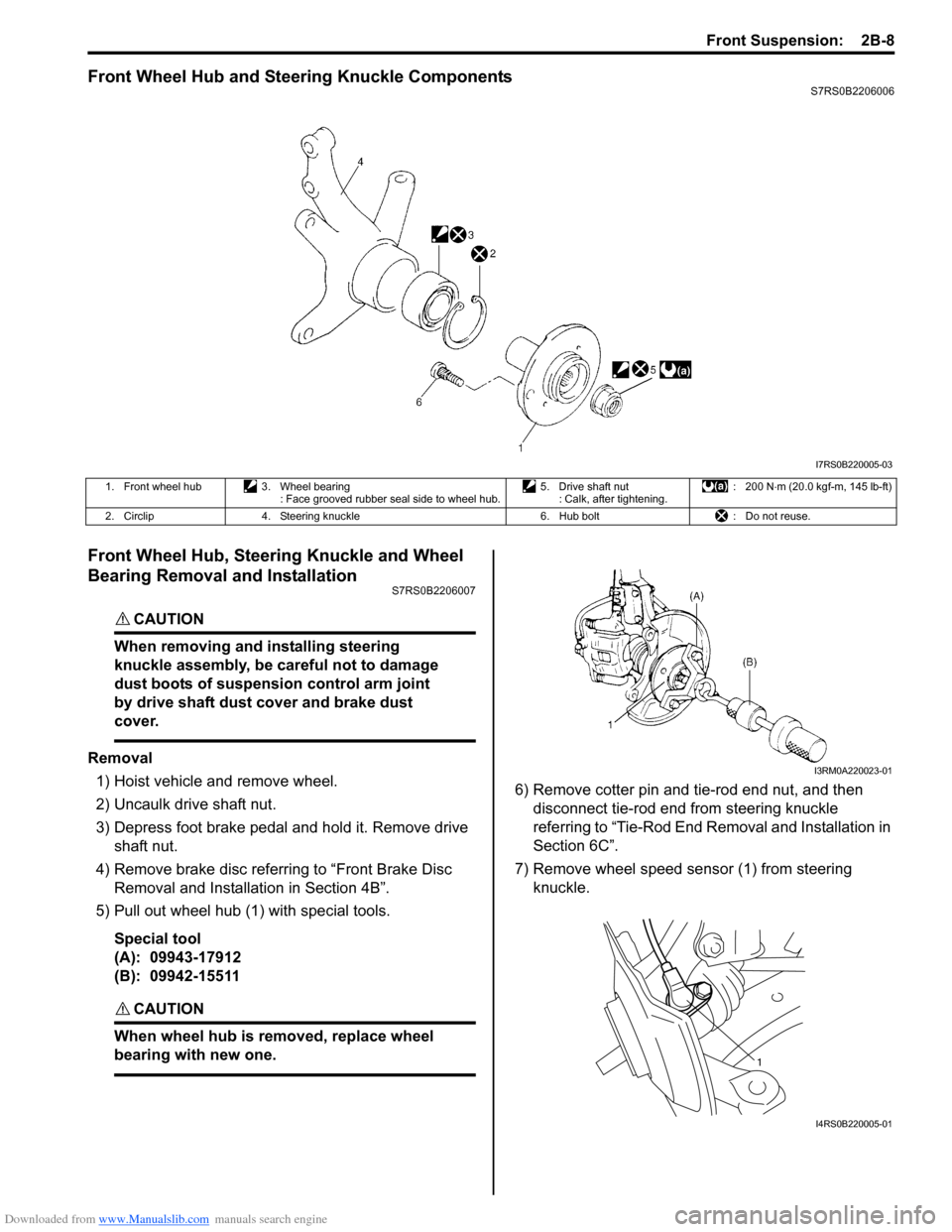
Front Wheel Hub and Steering Knuckle ComponentsS7RS0B2206006
Front Wheel Hub, Steering Knuckle and Wheel
Bearing Removal and Installation
S7RS0B2206007
CAUTION!
When removing and installing steering
knuckle assembly, be careful not to damage
dust boots of suspension control arm joint
by drive shaft dust cover and brake dust
cover.
Removal1) Hoist vehicle and remove wheel.
2) Uncaulk drive shaft nut.
3) Depress foot brake pedal and hold it. Remove drive shaft nut.
4) Remove brake disc referring to “Front Brake Disc Removal and Installa tion in Section 4B”.
5) Pull out wheel hub (1) with special tools.
Special tool
(A): 09943-17912
(B): 09942-15511
CAUTION!
When wheel hub is removed, replace wheel
bearing with new one.
6) Remove cotter pin and tie-rod end nut, and then disconnect tie-rod end from steering knuckle
referring to “Tie-Rod End Removal and Installation in
Section 6C”.
7) Remove wheel speed sensor (1) from steering knuckle.
I7RS0B220005-03
1. Front wheel hub 3. Wheel bearing
: Face grooved rubber seal side to wheel hub. 5. Drive shaft nut
: Calk, after tightening. : 200 N
⋅m (20.0 kgf-m, 145 lb-ft)
2. Circlip 4. Steering knuckle 6. Hub bolt: Do not reuse.
I3RM0A220023-01
1
I4RS0B220005-01
Page 442 of 1496

Downloaded from www.Manualslib.com manuals search engine 2B-9 Front Suspension:
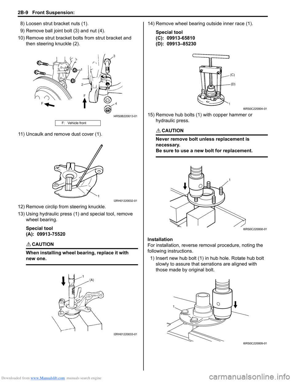
8) Loosen strut bracket nuts (1).
9) Remove ball joint bolt (3) and nut (4).
10) Remove strut bracket bolt s from strut bracket and
then steering knuckle (2).
11) Uncaulk and remove dust cover (1).
12) Remove circlip from steering knuckle.
13) Using hydraulic press (1) and special tool, remove wheel bearing.
Special tool
(A): 09913-75520
CAUTION!
When installing wheel bearing, replace it with
new one.
14) Remove wheel bearing outside inner race (1).
Special tool
(C): 09913-65810
(D): 09913–85230
15) Remove hub bolts (1) with copper hammer or hydraulic press.
CAUTION!
Never remove bolt unle ss replacement is
necessary.
Be sure to use a new bolt for replacement.
Installation
For installation, reverse removal procedure, noting the
following instructions.
1) Insert new hub bolt (1) in hub hole. Rotate hub bolt slowly to assure that serrations are aligned with
those made by original bolt.
F: Vehicle front
I4RS0B220013-01
I2RH01220032-01
I2RH01220033-01
I6RS0C220004-01
1
I6RS0C220008-01
1
I6RS0C220009-01
Page 443 of 1496
Downloaded from www.Manualslib.com manuals search engine Front Suspension: 2B-10
2) Face grooved rubber seal side (1) of new wheel bearing (2) upward as shown in figure and press-fit it
into knuckle (3) using special tool.
Special tool
(A): 09913-75510
(B): 09926–68310
(C): 09951–18210
CAUTION!
When installing wheel bearing, replace wheel
bearing and circlip with new one.
3) Install circlip (1).
4) Drive in dust cover so that dimensions “a” and “b” become equal as shown in the figure.
CAUTION!
When drive in dust cover, be careful not to
deform it.
5) Caulk more than 6 places with a punch.
6) Using special tool and hydraulic press, press fit
wheel hub (1) into wheel bearing (2) (Face grooved
rubber seal side to wheel hub).
Special tool
(A): 09913–75510
I3RM0A220032-01
I2RH01220037-01
I2RH01220038-01
I2RH01220039-01
I3RM0A220026-01
Page 455 of 1496
Downloaded from www.Manualslib.com manuals search engine Rear Suspension: 2C-1
Suspension
Rear Suspension
General Description
Rear Suspension ConstructionS7RS0B2301001
I6RS0C230001-03
A: View A7. Circlip 14. Spindle cap : 90 N⋅m (9.0 kgf-m, 65.0 lb-ft)
1. Rear coil spring 8. Rear trailing arm bolt 15. Wheel hub : 85 N⋅m (8.5 kgf-m, 61.5 lb-ft)
2. Rear spring upper seat 9. Rear shock absorber upper
nut 16. Washer
: 175 N⋅m (17.5 kgf-m, 126.5 lb-ft)
3. Rear shock absorber 10. Rear shock absorber lower nut “F”: Vehicle front : 88 N⋅m (8.8 kgf-m, 64.0 lb-ft)
4. Rear axle 11. Rear spindle bolt “I”: Body inside : Do not reuse.
5. Wheel bearing : Seal side of bearing comes
brake back plate side. 12. Wheel nut
: 73 N⋅m (7.3 kgf-m, 53.0 lb-ft)
6. Brake disc 13. Rear spindle nut
: Caulk spindle nut as shown
“a”. :28 N
⋅m (2.8 kgf-m, 20.0 lb-ft)