Page 1317 of 1496
Downloaded from www.Manualslib.com manuals search engine Instrumentation / Driver Info. / Horn: 9C-22
Remote Audio Control Switch Inspection (If
Equipped)
S7RS0B9306024
1) Remove driver air bag (inflator) module referring to
“Driver Air Bag (Inflator) Module Removal and
Installation in Section 8B”.
2) Disconnect remote audio control switch connector
from contact coil.
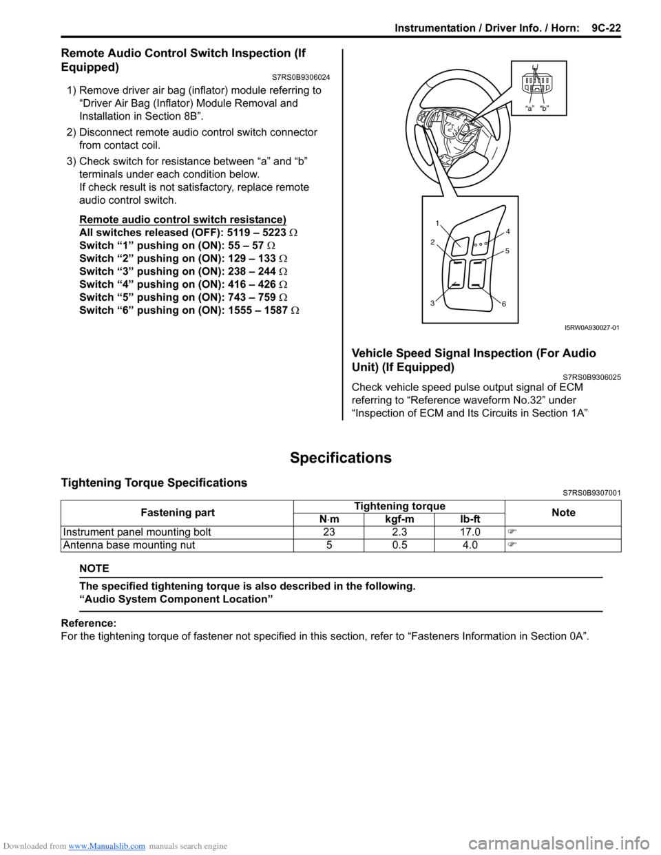
3) Check switch for resistance between “a” and “b” terminals under each condition below.
If check result is not satisfactory, replace remote
audio control switch.
Remote audio control switch resistance)
All switches released (OFF): 5119 – 5223 Ω
Switch “1” pushing on (ON): 55 – 57 Ω
Switch “2” pushing on (ON): 129 – 133 Ω
Switch “3” pushing on (ON): 238 – 244 Ω
Switch “4” pushing on (ON): 416 – 426 Ω
Switch “5” pushing on (ON): 743 – 759 Ω
Switch “6” pushing on (ON): 1555 – 1587 Ω
Vehicle Speed Signal Inspection (For Audio
Unit) (If Equipped)
S7RS0B9306025
Check vehicle speed pulse output signal of ECM
referring to “Reference waveform No.32” under
“Inspection of ECM and Its Circuits in Section 1A”
Specifications
Tightening Torque SpecificationsS7RS0B9307001
NOTE
The specified tightening torque is also described in the following.
“Audio System Component Location”
Reference:
For the tightening torque of fastener not specified in this section, refer to “Fasteners Information in Section 0A”.
“b”“a”
1
2
3 4
5
6
I5RW0A930027-01
Fastening part Tightening torque
Note
N ⋅mkgf-mlb-ft
Instrument panel mounting bolt 23 2.3 17.0 �)
Antenna base mounting nut 5 0.5 4.0 �)
Page 1327 of 1496
Downloaded from www.Manualslib.com manuals search engine Wipers / Washers: 9D-10
Rear Wiper Relay Removal and InstallationS7RS0B9406012
Removal1) Disconnect negative (–) cable at battery.
2) Remove junction block assembly referring to “BCM (Included in Junction Block Assembly) Removal and
Installation in Section 10B”.
3) Remove rear wiper relay.
Installation
Reverse removal procedure for installation.
Rear Wiper Relay InspectionS7RS0B9406013
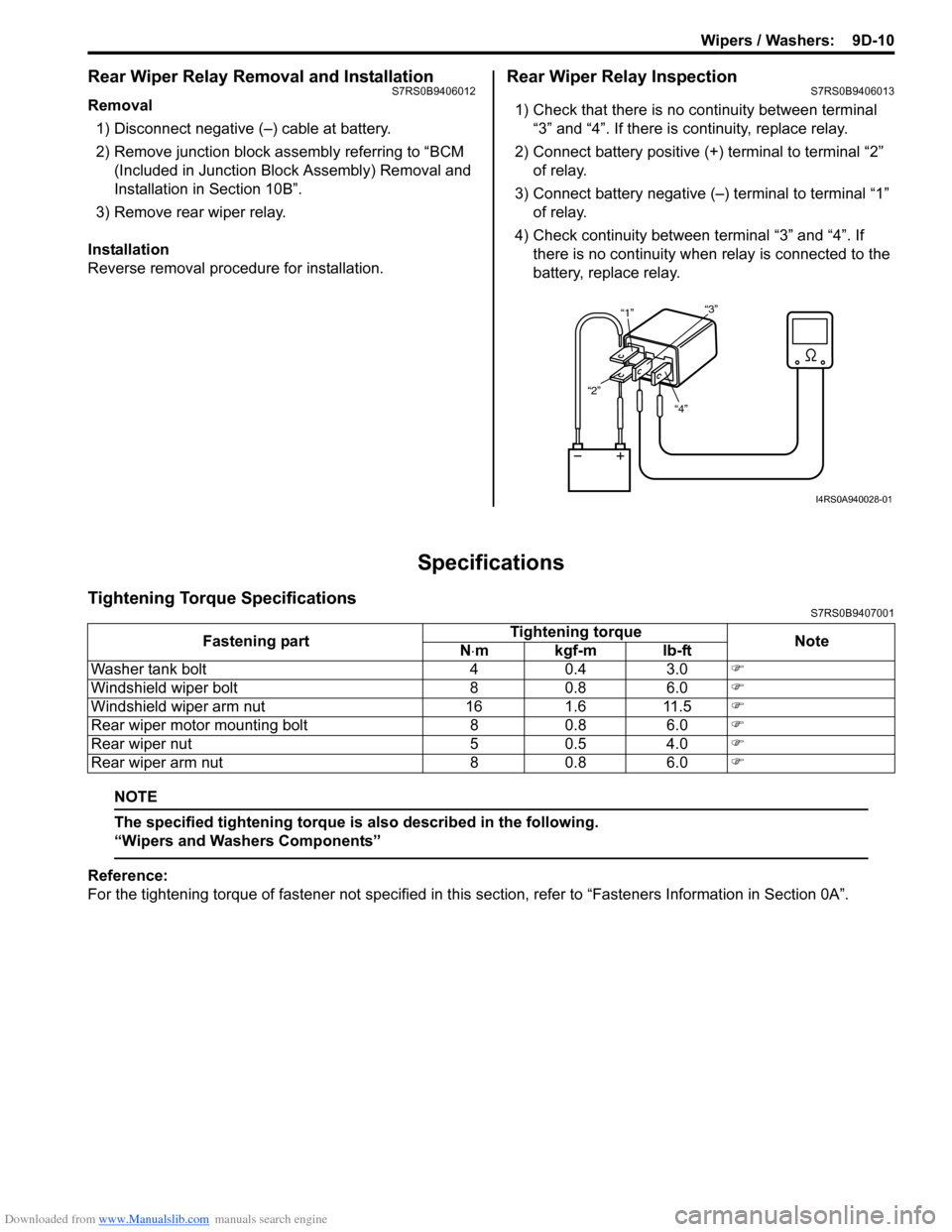
1) Check that there is no continuity between terminal “3” and “4”. If there is continuity, replace relay.
2) Connect battery positive (+ ) terminal to terminal “2”
of relay.
3) Connect battery negative (–) terminal to terminal “1” of relay.
4) Check continuity between terminal “3” and “4”. If
there is no continuity when relay is connected to the
battery, replace relay.
Specifications
Tightening Torque SpecificationsS7RS0B9407001
NOTE
The specified tightening torque is also described in the following.
“Wipers and Washers Components”
Reference:
For the tightening torque of fastener not specified in this section, refer to “Fasteners Information in Section 0A”.
“4”
“2” “1”
“3”
I4RS0A940028-01
Fastening part Tightening torque
Note
N ⋅mkgf-mlb-ft
Washer tank bolt 4 0.4 3.0 �)
Windshield wiper bolt 8 0.8 6.0 �)
Windshield wiper arm nut 16 1.6 11.5 �)
Rear wiper motor mounting bolt 8 0.8 6.0 �)
Rear wiper nut 5 0.5 4.0 �)
Rear wiper arm nut 8 0.8 6.0 �)
Page 1333 of 1496
Downloaded from www.Manualslib.com manuals search engine Glass / Windows / Mirrors: 9E-6
8) Using new brush, apply sufficient amount of primer onto glass along glass edge.
NOTE
• Be sure to refer to maker’s instruction for
proper handling and drying time.
• Do not apply primer on outside of ceramic coated surface.
• Do not touch primer coated surface.
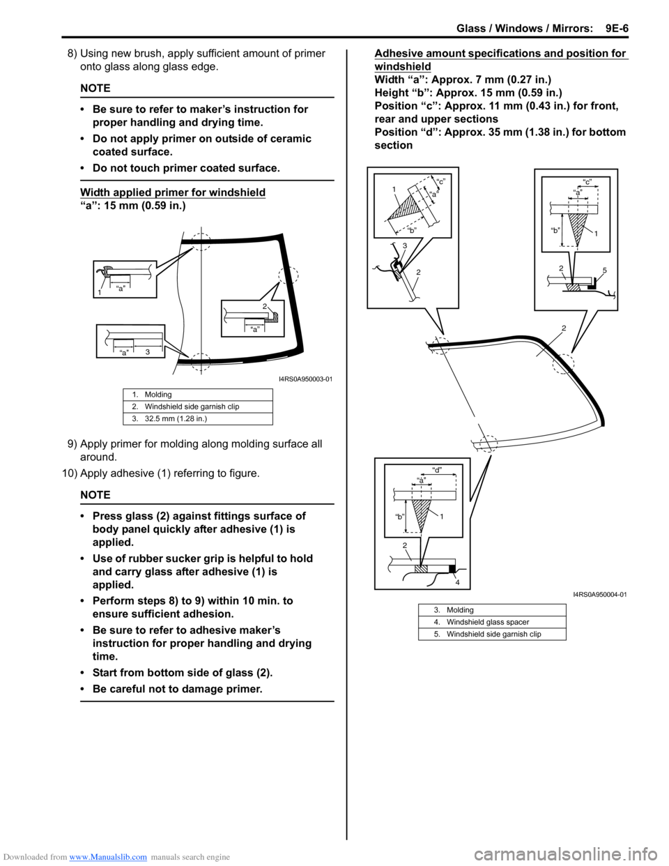
Width applied primer for windshield
“a”: 15 mm (0.59 in.)
9) Apply primer for molding along molding surface all around.
10) Apply adhesive (1) referring to figure.
NOTE
• Press glass (2) against fittings surface of body panel quickly after adhesive (1) is
applied.
• Use of rubber sucker gr ip is helpful to hold
and carry glass after adhesive (1) is
applied.
• Perform steps 8) to 9) within 10 min. to ensure sufficient adhesion.
• Be sure to refer to adhesive maker’s instruction for proper handling and drying
time.
• Start from bottom side of glass (2).
• Be careful not to damage primer.
Adhesive amount specifications and position for
windshield
Width “a”: Approx. 7 mm (0.27 in.)
Height “b”: Approx. 15 mm (0.59 in.)
Position “c”: Approx. 11 mm (0.43 in.) for front,
rear and upper sections
Position “d”: Approx. 35 mm (1.38 in.) for bottom
section
1. Molding
2. Windshield side garnish clip
3. 32.5 mm (1.28 in.)
“a”
1
“a”
“a”
2
3
I4RS0A950003-01
3. Molding
4. Windshield glass spacer
5. Windshield side garnish clip
2
2
4
1
“b” “d”
“b”
“c”
2
1
“a”
3
2
1
“b”
“c”
5
“a”
“a”
I4RS0A950004-01
Page 1340 of 1496
Downloaded from www.Manualslib.com manuals search engine 9E-13 Glass / Windows / Mirrors:
Rear End Door Window ComponentsS7RS0B9506010
Rear End Door Glass Removal and InstallationS7RS0B9506011
Refer to “Windshield Removal and Installation” as
removal and installation procedures are basically the
same. However, note the following.
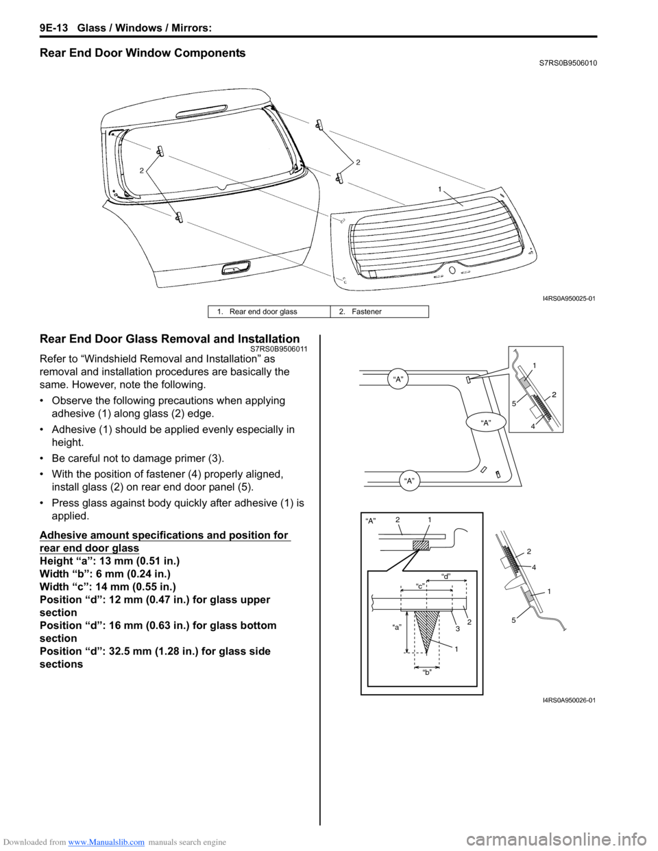
• Observe the following precautions when applying adhesive (1) along glass (2) edge.
• Adhesive (1) should be app lied evenly especially in
height.
• Be careful not to damage primer (3).
• With the position of fastener (4) properly aligned, install glass (2) on rear end door panel (5).
• Press glass against body quickly after adhesive (1) is applied.
Adhesive amount specifications and position for
rear end door glass
Height “a”: 13 mm (0.51 in.)
Width “b”: 6 mm (0.24 in.)
Width “c”: 14 mm (0.55 in.)
Position “d”: 12 mm (0.47 in.) for glass upper
section
Position “d”: 16 mm (0.63 in.) for glass bottom
section
Position “d”: 32.5 mm (1.28 in.) for glass side
sections
I4RS0A950025-01
1. Rear end door glass 2. Fastener
“A”
“A”
“A”
“A”
“c”“d”
“a” “b”
21
2
3
1
2
1
1
2
5
2
4
4
5
I4RS0A950026-01
Page 1361 of 1496
Downloaded from www.Manualslib.com manuals search engine Security and Locks: 9F-15
Keyless Entry Receiver and Its Circuit InspectionS7RS0B9606018
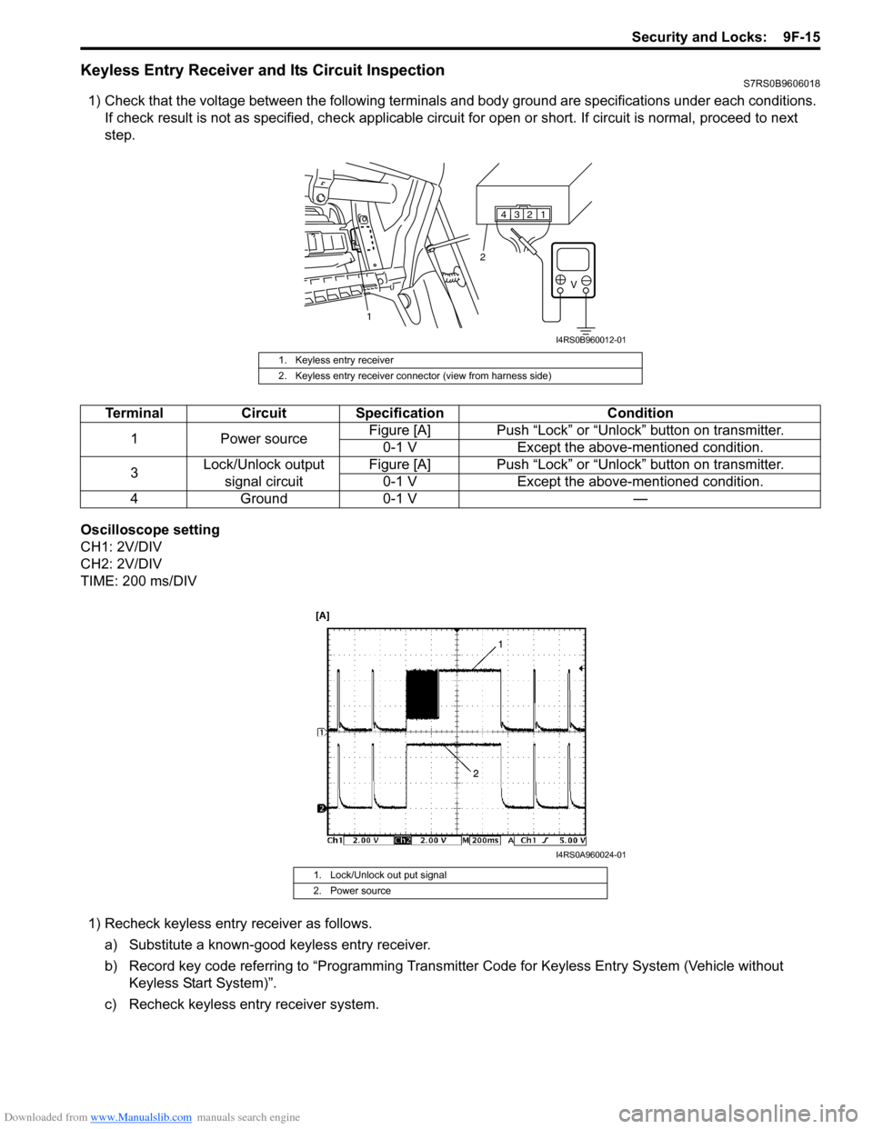
1) Check that the voltage between the following terminals and body ground are specifications under each conditions.
If check result is not as specified, ch eck applicable circuit for open or short. If circuit is normal, proceed to next
step.
Oscilloscope setting
CH1: 2V/DIV
CH2: 2V/DIV
TIME: 200 ms/DIV 1) Recheck keyless entry receiver as follows.
a) Substitute a known-good keyless entry receiver.
b) Record key code referring to “Programming Transmit ter Code for Keyless Entry System (Vehicle without
Keyless Start System)”.
c) Recheck keyless entry receiver system.
1. Keyless entry receiver
2. Keyless entry receiver connector (view from harness side)
1234
V
1 2
I4RS0B960012-01
Terminal
Circuit Specification Condition
1 Power source Figure [A] Push “Lock” or “Unlock” button on transmitter.
0-1 V Except the above-mentioned condition.
3 Lock/Unlock output
signal circuit Figure [A] Push “Lock” or “Unlock” button on transmitter.
0-1 V Except the above-mentioned condition.
4G ro un d0 -1 V —
1. Lock/Unlock out put signal
2. Power source
I4RS0A960024-01
Page 1362 of 1496
Downloaded from www.Manualslib.com manuals search engine 9F-16 Security and Locks:
Specifications
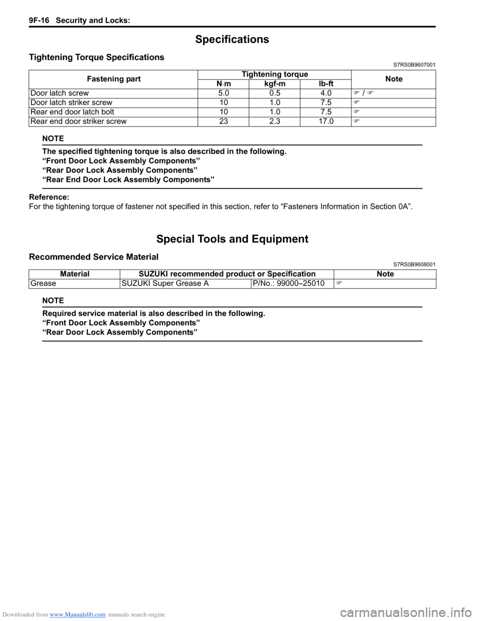
Tightening Torque SpecificationsS7RS0B9607001
NOTE
The specified tightening torque is also described in the following.
“Front Door Lock Assembly Components”
“Rear Door Lock Assembly Components”
“Rear End Door Lock Assembly Components”
Reference:
For the tightening torque of fastener not specified in this section, refer to “Fasteners Information in Section 0A”.
Special Tools and Equipment
Recommended Service MaterialS7RS0B9608001
NOTE
Required service material is also described in the following.
“Front Door Lock Assembly Components”
“Rear Door Lock Assembly Components”
Fastening part Tightening torque
Note
N ⋅mkgf-mlb-ft
Door latch screw 5.0 0.5 4.0 �) / �)
Door latch striker screw 10 1.0 7.5 �)
Rear end door latch bolt 10 1.0 7.5 �)
Rear end door striker screw 23 2.3 17.0 �)
MaterialSUZUKI recommended product or Specification Note
Grease SUZUKI Super Grease A P/No.: 99000–25010�)
Page 1364 of 1496
Downloaded from www.Manualslib.com manuals search engine 9G-2 Seats:
Front Seat Removal and InstallationS7RS0B9706002
WARNING!
Refer to “Air Bag Warning in Section 00” before starting service work.
Removal1) Disable air bag system referring to “Disabling Air Bag System in Section 8B”.
2) Disconnect couplers for seat harness and side air bag, if equipped.
3) Remove 4 mounting bolts to remove seat assembly.
4) Disassemble and repair seat if necessary.
Installation
Reverse removal procedure to install front seat.
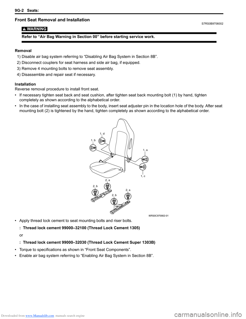
• If necessary tighten seat back and seat cushion, after tighten seat back mounting bolt (1) by hand, tighten completely as shown according to the alphabetical order.
• In the case of installing seat assembly to the body, insert se at adjuster pin in the location hole of the body. After seat
mounting bolt (2) is tightened by t he hand, tighten completely as shown according to the alphabetical order.
• Apply thread lock cement to seat mounting bolts and riser bolts. : Thread lock cement 99000–32100 (Thread Lock Cement 1305)
or
: Thread lock cement 99000–32030 (Thread Lock Cement Super 1303B)
• Torque to specifications as shown in “Front Seat Components”.
• Enable air bag system referring to “Enabling Air Bag System in Section 8B”.
1, d
1, b
1, a
1, c
2, a
2, b2, a
2, b
I6RS0C970002-01
Page 1366 of 1496
Downloaded from www.Manualslib.com manuals search engine 9G-4 Seats:
Rear Seat Removal and InstallationS7RS0B9706004
Removal1) Fold rear seat back forward.
2) Remove seat mounting bolts and nuts to remove seat assembly.
3) Disassemble and repair seat as necessary.
Installation
Reverse removal procedure to install rear seat.
• Tighten seat back striker mounting bolts according to “Rear Seat Components”.
• Torque to specifications in “Rear Seat Components”.
• When installing seat cushion, align seat cushion hook with center hinge bracket.
Specifications
Tightening Torque SpecificationsS7RS0B9707001
NOTE
The specified tightening torque is also described in the following.
“Front Seat Components”
“Rear Seat Components”
Reference:
For the tightening torque of fastener not specified in this section, refer to “Fasteners Information in Section 0A”.
Special Tools and Equipment
Recommended Service MaterialS7RS0B9708001
NOTE
Required service material is also described in the following.
“Front Seat Components”
Material SUZUKI recommended product or Specification Note
Thread lock cement Thread Lock Cement Super 1303B P/No.: 99000–32030 �)
Thread Lock Cement 1305 P/No.: 99000–32100 �)