2006 SUZUKI SWIFT air con
[x] Cancel search: air conPage 1437 of 1496
Downloaded from www.Manualslib.com manuals search engine Body Electrical Control System: 10B-34
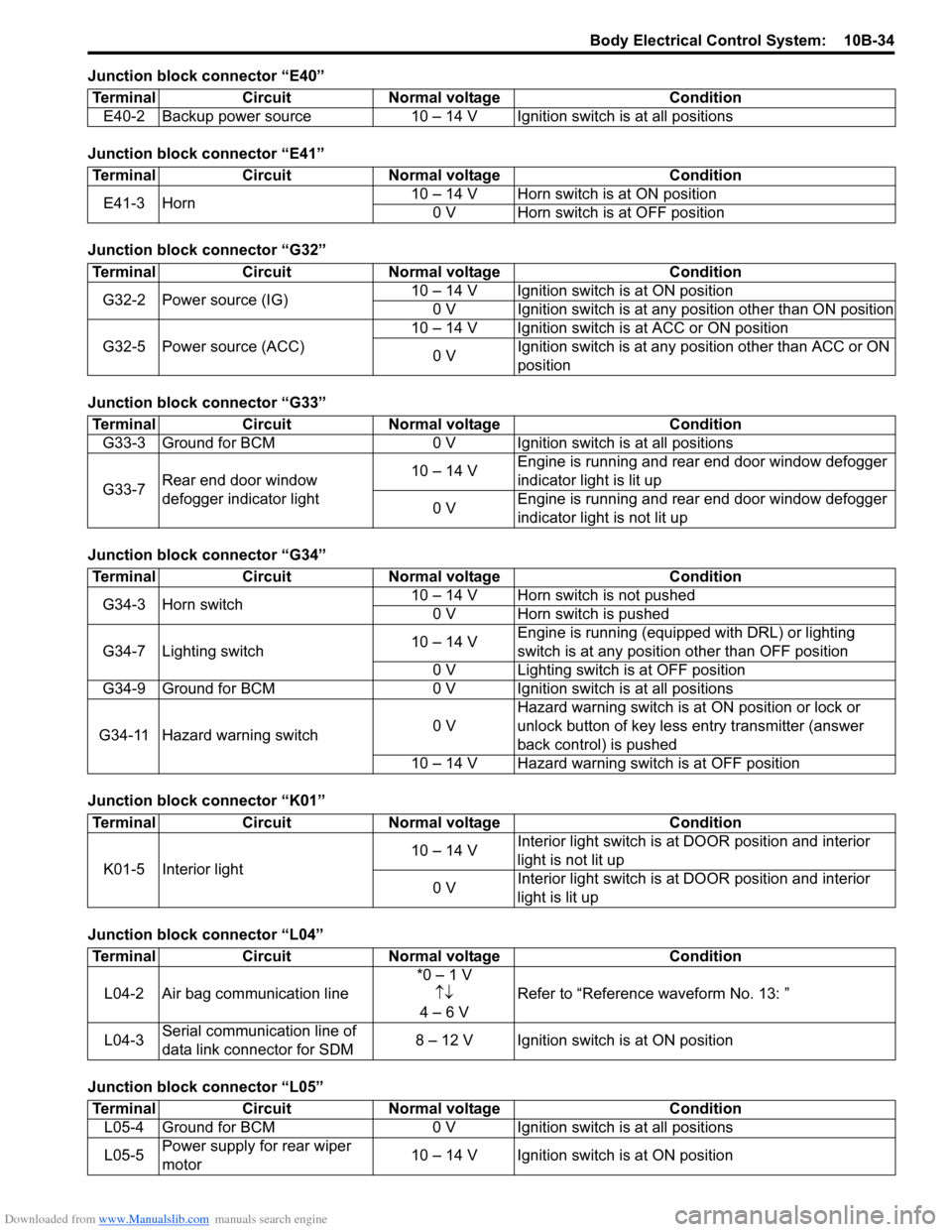
Junction block connector “E40”
Junction block connector “E41”
Junction block connector “G32”
Junction block connector “G33”
Junction block connector “G34”
Junction block connector “K01”
Junction block connector “L04”
Junction block connector “L05”Terminal Circuit Normal voltage Condition
E40-2 Backup power source 10 – 14 V Igni tion switch is at all positions
TerminalCircuitNormal voltage Condition
E41-3 Horn 10 – 14 V Horn switch is at ON position
0 V Horn switch is at OFF position
Terminal CircuitNormal voltage Condition
G32-2 Power source (IG) 10 – 14 V Ignition switch is at ON position
0 V Ignition switch is at any position other than ON position
G32-5 Power source (ACC) 10 – 14 V Ignition switch is at ACC or ON position
0 V Ignition switch is at any position other than ACC or ON
position
Terminal
CircuitNormal voltage Condition
G33-3 Ground for BCM 0 V Ignition switch is at all positions
G33-7 Rear end door window
defogger indicator light 10 – 14 V
Engine is running and rear end door window defogger
indicator light is lit up
0 V Engine is running and rear end door window defogger
indicator light is not lit up
Terminal
CircuitNormal voltage Condition
G34-3 Horn switch 10 – 14 V Horn switch is not pushed
0 V Horn switch is pushed
G34-7 Lighting switch 10 – 14 VEngine is running (equipped with DRL) or lighting
switch is at any position other than OFF position
0 V Lighting switch is at OFF position
G34-9 Ground for BCM 0 V Ignition switch is at all positions
G34-11 Hazard warning switch 0 VHazard warning switch is at
ON position or lock or
unlock button of key less entry transmitter (answer
back control) is pushed
10 – 14 V Hazard warning switch is at OFF position
Terminal CircuitNormal voltage Condition
K01-5 Interior light 10 – 14 V
Interior light switch is at
DOOR position and interior
light is not lit up
0 V Interior light switch is at
DOOR position and interior
light is lit up
Terminal CircuitNormal voltage Condition
L04-2 Air bag communication line *0 – 1 V
↑↓
4 – 6 V Refer to “Reference
waveform No. 13: ”
L04-3 Serial communication line of
data link connector for SDM 8 – 12 V Ignition switch is at ON position
Terminal
CircuitNormal voltage Condition
L05-4 Ground for BCM 0 V Ignition switch is at all positions
L05-5 Power supply for rear wiper
motor 10 – 14 V Ignition switch is at ON position
Page 1442 of 1496
Downloaded from www.Manualslib.com manuals search engine 10B-39 Body Electrical Control System:
Repair Instructions
BCM (Included in Junction Block Assembly)
Removal and Installation
S7RS0BA206001
CAUTION!
Do not attempt removal of BCM from junction
block assembly as it may cause contact
failure.
If there is faulty condition in BCM, replace
junction block assembly.
Removal
1) Disconnect negative (–) cable from battery.
2) Disable air bag system referring to “Disabling Air Bag System in Section 8B”.
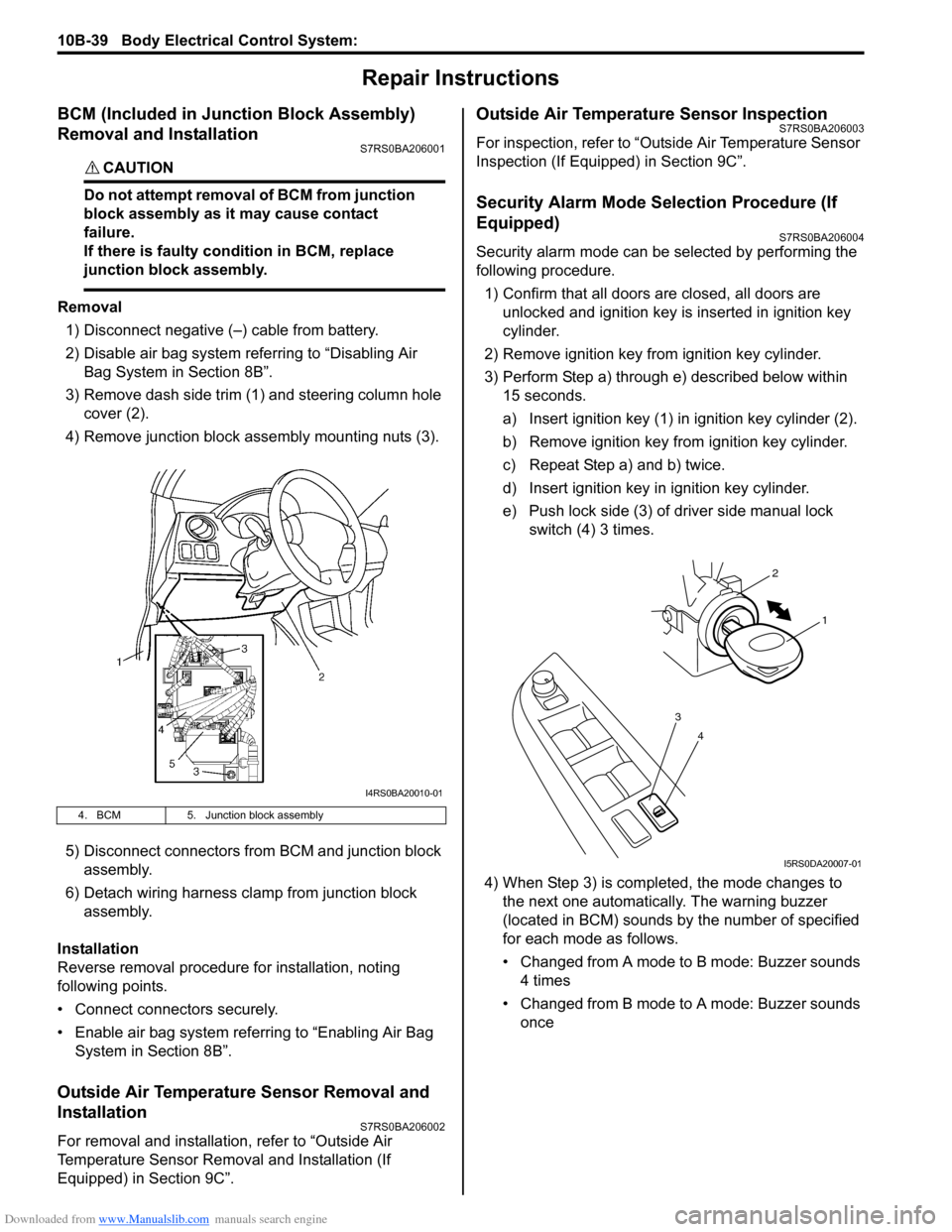
3) Remove dash side trim (1) and steering column hole cover (2).
4) Remove junction block assembly mounting nuts (3).
5) Disconnect connectors from BCM and junction block assembly.
6) Detach wiring harness clamp from junction block assembly.
Installation
Reverse removal procedure for installation, noting
following points.
• Connect connectors securely.
• Enable air bag system referring to “Enabling Air Bag System in Section 8B”.
Outside Air Temperature Sensor Removal and
Installation
S7RS0BA206002
For removal and installation, refer to “Outside Air
Temperature Sensor Removal and Installation (If
Equipped) in Section 9C”.
Outside Air Temperature Sensor InspectionS7RS0BA206003
For inspection, refer to “Outside Air Temperature Sensor
Inspection (If Equipped) in Section 9C”.
Security Alarm Mode Selection Procedure (If
Equipped)
S7RS0BA206004
Security alarm mode can be selected by performing the
following procedure.
1) Confirm that all doors are closed, all doors are unlocked and ignition key is inserted in ignition key
cylinder.
2) Remove ignition key from ignition key cylinder.
3) Perform Step a) through e) described below within 15 seconds.
a) Insert ignition key (1) in ignition key cylinder (2).
b) Remove ignition key from ignition key cylinder.
c) Repeat Step a) and b) twice.
d) Insert ignition key in ignition key cylinder.
e) Push lock side (3) of driver side manual lock switch (4) 3 times.
4) When Step 3) is completed, the mode changes to the next one automatically. The warning buzzer
(located in BCM) sounds by the number of specified
for each mode as follows.
• Changed from A mode to B mode: Buzzer sounds 4 times
• Changed from B mode to A mode: Buzzer sounds once
4. BCM 5. Junction block assembly
I4RS0BA20010-01
4
3
1
2
I5RS0DA20007-01
Page 1451 of 1496
Downloaded from www.Manualslib.com manuals search engine Immobilizer Control System: 10C-8
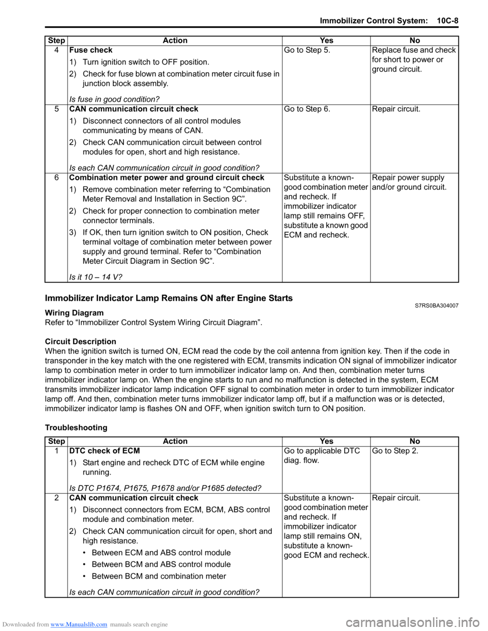
Immobilizer Indicator Lamp Remains ON after Engine StartsS7RS0BA304007
Wiring Diagram
Refer to “Immobilizer Control S ystem Wiring Circuit Diagram”.
Circuit Description
When the ignition switch is turned ON, ECM read the code by the coil antenna from ignition key. Then if the code in
transponder in the key match with the one registered with ECM, transmits indication ON signal of immobilizer indicator
lamp to combination meter in order to turn immobilizer indicator lamp on. And then, combination meter turns
immobilizer indicator lamp on. When th e engine starts to run and no malfunction is detected in the system, ECM
transmits immobilizer indicator lamp indication O FF signal to combination meter in order to turn immobilizer indicator
lamp off. And then, comb ination meter turns immobilizer indicator lamp off, but if a malfunction was or is detected,
immobilizer indicator lamp is flashes ON and OF F, when ignition switch turn to ON position.
Troubleshooting 4
Fuse check
1) Turn ignition switch to OFF position.
2) Check for fuse blown at combination meter circuit fuse in
junction block assembly.
Is fuse in good condition? Go to Step 5. Replace fuse and check
for short to power or
ground circuit.
5 CAN communication circuit check
1) Disconnect connectors of all control modules
communicating by means of CAN.
2) Check CAN communication circuit between control modules for open, short and high resistance.
Is each CAN communication circuit in good condition? Go to Step 6. Repair circuit.
6 Combination meter power and ground circuit check
1) Remove combination meter referring to “Combination
Meter Removal and Installation in Section 9C”.
2) Check for proper connection to combination meter connector terminals.
3) If OK, then turn ignition switch to ON position, Check terminal voltage of combination meter between power
supply and ground terminal. Refer to “Combination
Meter Circuit Diagram in Section 9C”.
Is it 10 – 14 V? Substitute a known-
good combination meter
and recheck. If
immobilizer indicator
lamp still remains OFF,
substitute a known good
ECM and recheck.
Repair power supply
and/or ground circuit.
Step Action Yes No
Step
Action YesNo
1 DTC check of ECM
1) Start engine and recheck DTC of ECM while engine
running.
Is DTC P1674, P1675, P1678 and/or P1685 detected? Go to applicable DTC
diag. flow.
Go to Step 2.
2 CAN communication circuit check
1) Disconnect connectors from ECM, BCM, ABS control
module and combination meter.
2) Check CAN communication circuit for open, short and high resistance.
• Between ECM and ABS control module
• Between BCM and ABS control module
• Between BCM and combination meter
Is each CAN communication circuit in good condition? Substitute a known-
good combination meter
and recheck. If
immobilizer indicator
lamp still remains ON,
substitute a known-
good ECM and recheck.
Repair circuit.
Page 1453 of 1496
Downloaded from www.Manualslib.com manuals search engine Immobilizer Control System: 10C-10
DTC Confirmation Procedure1) Register the transponder code in the transponder in the ignition key with ECM referring to “Registration of the
Ignition Key”.
2) Check DTC in ECM.
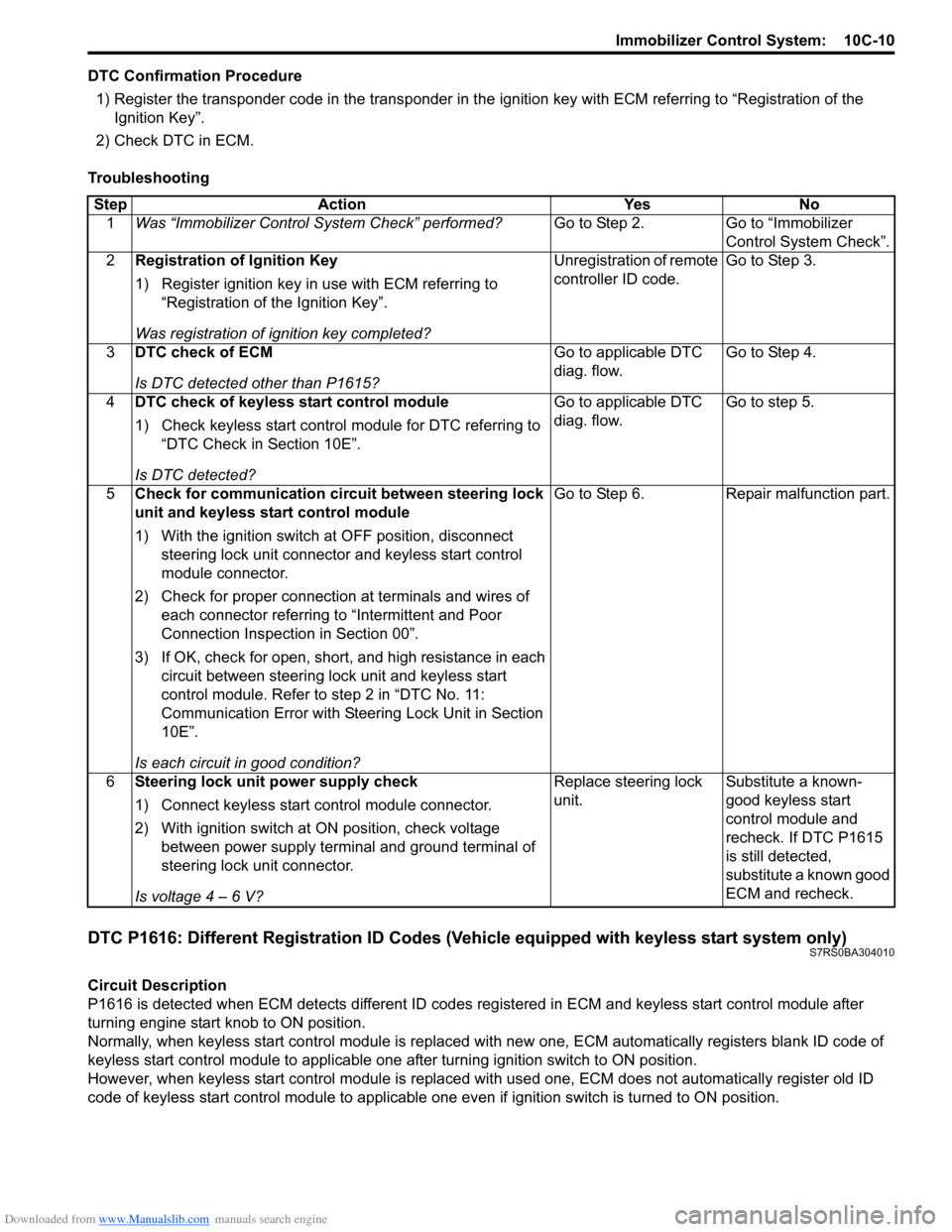
Troubleshooting
DTC P1616: Different Registration ID Codes (Vehicle equipped with keyless start system only)S7RS0BA304010
Circuit Description
P1616 is detected when ECM detects different ID codes registered in ECM and keyless start control module after
turning engine start knob to ON position.
Normally, when keyless start control module is replaced with new one, ECM automatically registers blank ID code of
keyless start control module to applicable one after turning ignition switch to ON position.
However, when keyless start control module is replaced wit h used one, ECM does not automatically register old ID
code of keyless start control module to applicable one ev en if ignition switch is turned to ON position.
Step Action Yes No
1 Was “Immobilizer Control S ystem Check” performed? Go to Step 2. Go to “Immobilizer
Control System Check”.
2 Registration of Ignition Key
1) Register ignition key in use with ECM referring to
“Registration of the Ignition Key”.
Was registration of ignition key completed? Unregistration of remote
controller ID code.
Go to Step 3.
3 DTC check of ECM
Is DTC detected other than P1615? Go to applicable DTC
diag. flow.
Go to Step 4.
4 DTC check of keyless start control module
1) Check keyless start control module for DTC referring to
“DTC Check in Section 10E”.
Is DTC detected? Go to applicable DTC
diag. flow.
Go to step 5.
5 Check for communication circuit between steering lock
unit and keyless start control module
1) With the ignition switch at OFF position, disconnect
steering lock unit connector and keyless start control
module connector.
2) Check for proper connection at terminals and wires of
each connector referring to “Intermittent and Poor
Connection Inspection in Section 00”.
3) If OK, check for open, short, and high resistance in each circuit between steering lock unit and keyless start
control module. Refer to step 2 in “DTC No. 11:
Communication Error with Steeri ng Lock Unit in Section
10E”.
Is each circuit in good condition? Go to Step 6. Repair malfunction part.
6 Steering lock unit power supply check
1) Connect keyless start control module connector.
2) With ignition switch at ON position, check voltage
between power supply terminal and ground terminal of
steering lock unit connector.
Is voltage 4 – 6 V? Replace steering lock
unit.
Substitute a known-
good keyless start
control module and
recheck. If DTC P1615
is still detected,
substitute a known good
ECM and recheck.
Page 1455 of 1496
Downloaded from www.Manualslib.com manuals search engine Immobilizer Control System: 10C-12
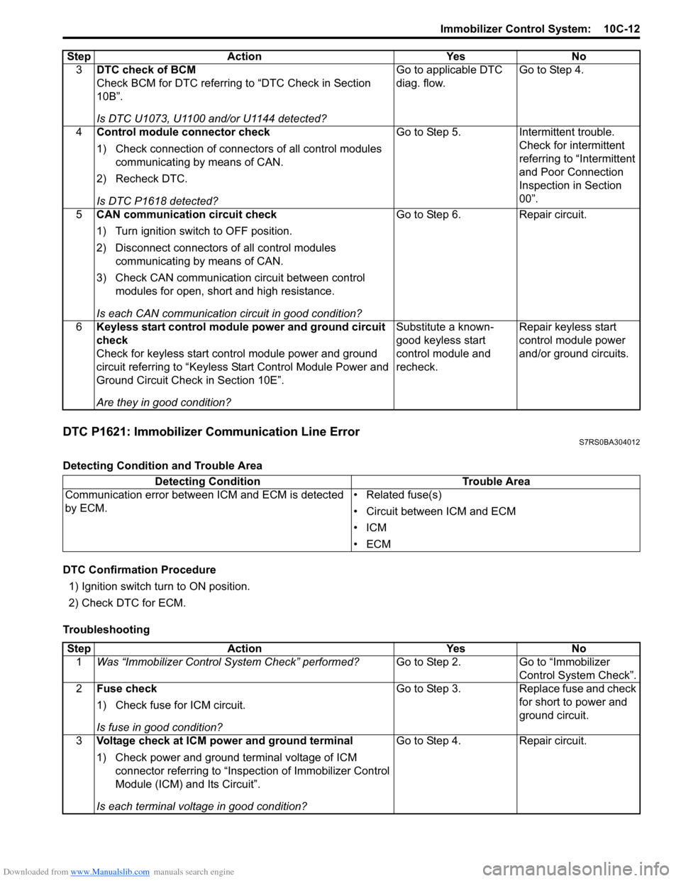
DTC P1621: Immobilizer Communication Line ErrorS7RS0BA304012
Detecting Condition and Trouble Area
DTC Confirmation Procedure1) Ignition switch turn to ON position.
2) Check DTC for ECM.
Troubleshooting 3
DTC check of BCM
Check BCM for DTC referring to “DTC Check in Section
10B”.
Is DTC U1073, U1100 and/or U1144 detected? Go to applicable DTC
diag. flow.
Go to Step 4.
4 Control module connector check
1) Check connection of connectors of all control modules
communicating by means of CAN.
2) Recheck DTC.
Is DTC P1618 detected? Go to Step 5. Intermittent trouble.
Check for intermittent
referring to “Intermittent
and Poor Connection
Inspection in Section
00”.
5 CAN communication circuit check
1) Turn ignition switch to OFF position.
2) Disconnect connectors of all control modules
communicating by means of CAN.
3) Check CAN communication circuit between control modules for open, short and high resistance.
Is each CAN communication circuit in good condition? Go to Step 6. Repair circuit.
6 Keyless start control module power and ground circuit
check
Check for keyless start control module power and ground
circuit referring to “Keyless St art Control Module Power and
Ground Circuit Check in Section 10E”.
Are they in good condition? Substitute a known-
good keyless start
control module and
recheck.
Repair keyless start
control module power
and/or ground circuits.
Step Action Yes No
Detecting Condition
Trouble Area
Communication error between ICM and ECM is detected
by ECM. • Related fuse(s)
• Circuit between ICM and ECM
•ICM
•ECM
Step
Action YesNo
1 Was “Immobilizer Control S ystem Check” performed? Go to Step 2.Go to “Immobilizer
Control System Check”.
2 Fuse check
1) Check fuse for ICM circuit.
Is fuse in good condition? Go to Step 3.
Replace fuse and check
for short to power and
ground circuit.
3 Voltage check at ICM power and ground terminal
1) Check power and ground terminal voltage of ICM
connector referring to “Inspe ction of Immobilizer Control
Module (ICM) and Its Circuit”.
Is each terminal voltage in good condition? Go to Step 4.
Repair circuit.
Page 1456 of 1496
Downloaded from www.Manualslib.com manuals search engine 10C-13 Immobilizer Control System:
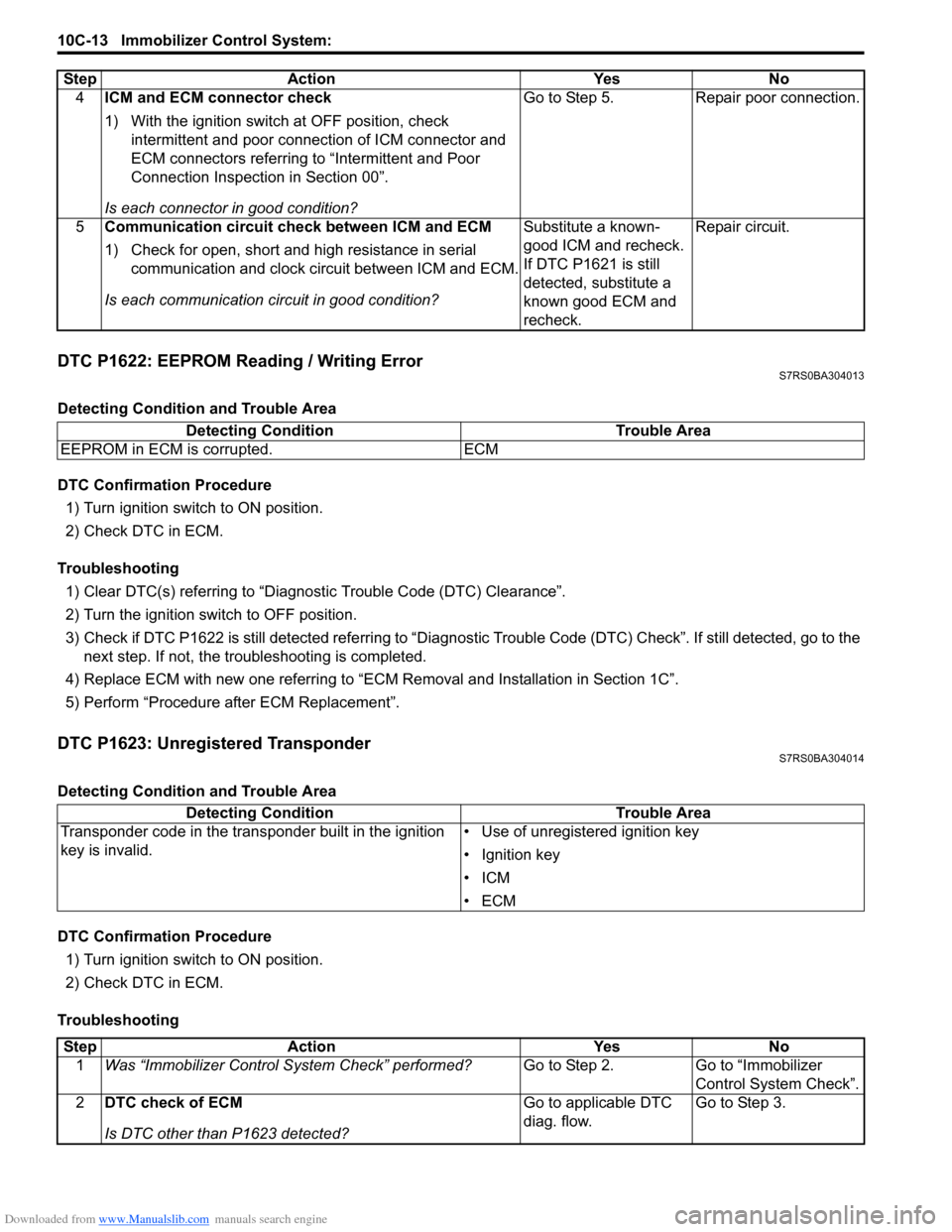
DTC P1622: EEPROM Reading / Writing ErrorS7RS0BA304013
Detecting Condition and Trouble Area
DTC Confirmation Procedure1) Turn ignition switch to ON position.
2) Check DTC in ECM.
Troubleshooting 1) Clear DTC(s) referring to “Diagnostic Trouble Code (DTC) Clearance”.
2) Turn the ignition switch to OFF position.
3) Check if DTC P1622 is still detected re ferring to “Diagnostic Trouble Code (DTC) Check”. If still detected, go to the
next step. If not, the troubleshooting is completed.
4) Replace ECM with new one referring to “ECM Removal and Installation in Section 1C”.
5) Perform “Procedure after ECM Replacement”.
DTC P1623: Unregistered TransponderS7RS0BA304014
Detecting Condition and Trouble Area
DTC Confirmation Procedure 1) Turn ignition switch to ON position.
2) Check DTC in ECM.
Troubleshooting 4
ICM and ECM connector check
1) With the ignition switch at OFF position, check
intermittent and poor connec tion of ICM connector and
ECM connectors referring to “Intermittent and Poor
Connection Inspection in Section 00”.
Is each connector in good condition? Go to Step 5. Repair poor connection.
5 Communication circuit check between ICM and ECM
1) Check for open, short and high resistance in serial
communication and clock circuit between ICM and ECM.
Is each communication circuit in good condition? Substitute a known-
good ICM and recheck.
If DTC P1621 is still
detected, substitute a
known good ECM and
recheck.Repair circuit.
Step Action Yes No
Detecting Condition
Trouble Area
EEPROM in ECM is corrupted. ECM
Detecting Condition Trouble Area
Transponder code in the transponder built in the ignition
key is invalid. • Use of unregistered ignition key
• Ignition key
•ICM
•ECM
Step
Action YesNo
1 Was “Immobilizer Control S ystem Check” performed? Go to Step 2.Go to “Immobilizer
Control System Check”.
2 DTC check of ECM
Is DTC other than P1623 detected? Go to applicable DTC
diag. flow.
Go to Step 3.
Page 1458 of 1496
Downloaded from www.Manualslib.com manuals search engine 10C-15 Immobilizer Control System:
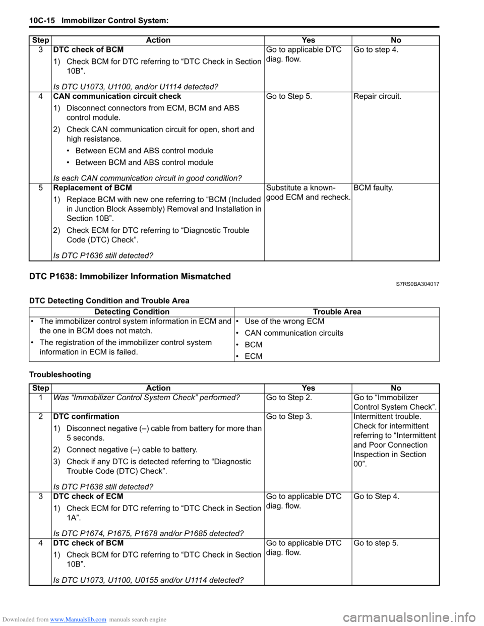
DTC P1638: Immobilizer Information MismatchedS7RS0BA304017
DTC Detecting Condition and Trouble Area
Troubleshooting3
DTC check of BCM
1) Check BCM for DTC referring to “DTC Check in Section
10B”.
Is DTC U1073, U1100, and/or U1114 detected? Go to applicable DTC
diag. flow.
Go to step 4.
4 CAN communication circuit check
1) Disconnect connectors from ECM, BCM and ABS
control module.
2) Check CAN communication circuit for open, short and high resistance.
• Between ECM and ABS control module
• Between BCM and ABS control module
Is each CAN communication circuit in good condition? Go to Step 5. Repair circuit.
5 Replacement of BCM
1) Replace BCM with new one referring to “BCM (Included
in Junction Block Assembly) Removal and Installation in
Section 10B”.
2) Check ECM for DTC referring to “Diagnostic Trouble Code (DTC) Check”.
Is DTC P1636 still detected? Substitute a known-
good ECM and recheck.
BCM faulty.
Step Action Yes No
Detecting Condition
Trouble Area
• The immobilizer control sys tem information in ECM and
the one in BCM does not match.
• The registration of the immobilizer control system
information in ECM is failed. • Use of the wrong ECM
• CAN communication circuits
•BCM
•ECM
Step
Action YesNo
1 Was “Immobilizer Control S ystem Check” performed? Go to Step 2.Go to “Immobilizer
Control System Check”.
2 DTC confirmation
1) Disconnect negative (–) cable from battery for more than
5 seconds.
2) Connect negative (–) cable to battery.
3) Check if any DTC is detecte d referring to “Diagnostic
Trouble Code (DTC) Check”.
Is DTC P1638 still detected? Go to Step 3.
Intermittent trouble.
Check for intermittent
referring to “Intermittent
and Poor Connection
Inspection in Section
00”.
3 DTC check of ECM
1) Check ECM for DTC referring to “DTC Check in Section
1A”.
Is DTC P1674, P1675, P1678 and/or P1685 detected? Go to applicable DTC
diag. flow.
Go to Step 4.
4 DTC check of BCM
1) Check BCM for DTC referring to “DTC Check in Section
10B”.
Is DTC U1073, U1100, U0155 and/or U1114 detected? Go to applicable DTC
diag. flow.
Go to step 5.
Page 1459 of 1496
Downloaded from www.Manualslib.com manuals search engine Immobilizer Control System: 10C-16
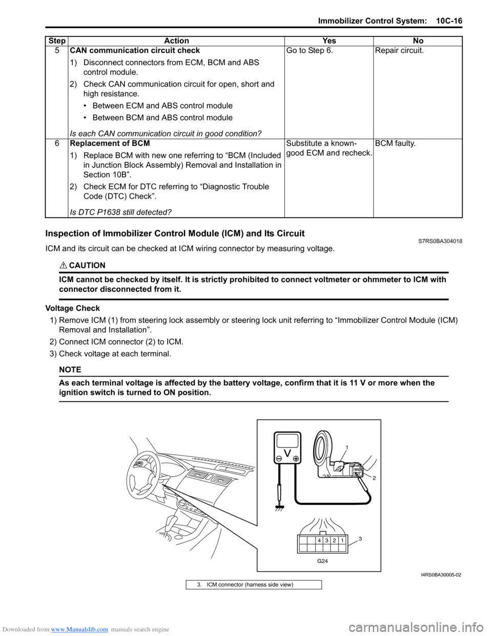
Inspection of Immobilizer Control Module (ICM) and Its CircuitS7RS0BA304018
ICM and its circuit can be checked at ICM wiring connector by measuring voltage.
CAUTION!
ICM cannot be checked by itself. It is strictly prohibited to connect voltmeter or ohmmeter to ICM with
connector disconnected from it.
Voltage Check
1) Remove ICM (1) from steering lock assembly or steering lock unit referrin g to “Immobilizer Control Module (ICM)
Removal and Installation”.
2) Connect ICM connector (2) to ICM.
3) Check voltage at each terminal.
NOTE
As each terminal voltage is affected by the battery voltage, confirm that it is 11 V or more when the
ignition switch is turned to ON position.
5 CAN communication circuit check
1) Disconnect connectors from ECM, BCM and ABS
control module.
2) Check CAN communication circuit for open, short and high resistance.
• Between ECM and ABS control module
• Between BCM and ABS control module
Is each CAN communication circuit in good condition? Go to Step 6. Repair circuit.
6 Replacement of BCM
1) Replace BCM with new one referring to “BCM (Included
in Junction Block Assembly) Removal and Installation in
Section 10B”.
2) Check ECM for DTC referring to “Diagnostic Trouble Code (DTC) Check”.
Is DTC P1638 still detected? Substitute a known-
good ECM and recheck.
BCM faulty.
Step Action Yes No
12
3
4
G24
1
2
3
I4RS0BA30005-02
3. ICM connector (harness side view)