2006 SUZUKI SWIFT eco
[x] Cancel search: ecoPage 221 of 1496

Downloaded from www.Manualslib.com manuals search engine Engine General Information and Diagnosis: 1A-171
DTC P2138: Throttle / Pedal Position Sensor / Switch “D”/“E” (Main / Sub) Voltage CorrelationS7RS0B1104077
Wiring Diagram
DTC Detecting Condition and Trouble Area
DTC Confirmation Procedure1) With ignition switch turned OFF, connect scan tool.
2) Turn ON ignition switch and clear DTC using scan tool.
3) Keep the accelerator pedal at idle position for 2 seconds.
4) Keep the accelerator pedal at fully depressed position for 2 seconds.
5) Repeat Step 3) and 4) for 3 times.
6) Check DTC.
E23 C37
34
1819
567
1011
17
20
47 46
495051
2122
52 16
25 9
24
14
29
55
57 54 53
59
60 58 2
262728
15
30
56 4832 31
34353637
40
42 39 38
44
45 43 41 331
1213
238
34
1819
567
1011
17
20
47 46
495051
2122
52 16
25 9
24
14
29
55
57 54 53
59
60 58 2
262728
15
30
56 48 32 31
34353637
40
42 39 38
44
45 43 41 331
1213
238
BRN
GRN
BLU
RED
YEL
WHT
E23-35
E23-37
E23-52
E23-34
E23-36
E23-51
E23-50 5 V
5 V
1
1-1 3 2
1-2
I4RS0B110047-01
1. APP sensor
1-2. APP sensor (sub) 3. Ground of APP sensor for shield wire
1-1. APP sensor (main) 2. ECM
DTC detecting condition Trouble area
Difference between the opening angle based on APP
sensor (main) and the op ening angle based on APP
sensor (sub) is more than sp ecification for specified time
continuously.
(1 driving detection logic) • APP sensor (main) and (sub) circuit
• APP sensor assembly
•ECM
Page 251 of 1496

Downloaded from www.Manualslib.com manuals search engine Engine General Information and Diagnosis: 1A-201
Troubleshooting
NOTE
When measuring circuit voltage, resistance and/or pulse signal at ECM connector, connect the special
tool to ECM and/or the ECM connectors referri ng to “Inspection of ECM and Its Circuits”.
StepAction YesNo
1 Fuel pump control system check for operation
Is fuel pump heard to operate 2 sec. after ignition switch is
turned ON? Fuel pump circuit is in
good condition.
Go to Step 2.
2 Fuel pump relay po wer supply check
1) Disconnect fuel pump relay from individual circuit fuse box No.1 with ignition switch turned OFF.
2) Check for proper connection to fuel pump relay at each terminal.
3) If OK, turn ON ignition switch, measure voltage between “BLK/WHT” wire terminal of fuel pump relay connector
and engine ground.
Is voltage 10 – 14 V? Go to Step 3.
“BLK/WHT” wire is open
or shorted to ground
circuit.
3 Fuel pump relay po wer supply check
1) Turn ON ignition switch, measure voltage between “BLK/ RED” wire terminal of fuel pump relay connector and
engine ground.
Is voltage 10 – 14 V? Go to Step 4.
“BLK/RED” wire is open
circuit.
4 Fuel pump relay check
1) Check fuel pump relay referring to “Main Relay, Fuel
Pump Relay and Starting Moto r Control Relay Inspection
in Section 1C”.
Is relay in good condition? Go to Step 5.
Faulty relay.
5 Fuel pump relay drive signal check
1) Connect fuel pump relay to individual circuit fuse box
No.1.
2) Connect voltmeter between “E23-15” terminal of ECM connector and vehicle body ground.
3) Measure voltage 2 second after ignition switch is turned ON.
Is voltage 10 – 14 V? Go to Step 6.
“GRN/WHT” wire is
open circuit or shorted
to ground circuit.
I2RH01110132-01
Page 252 of 1496

Downloaded from www.Manualslib.com manuals search engine 1A-202 Engine General Information and Diagnosis:
6Fuel pump relay drive signal check
1) Measure voltage within 2 second after ignition switch is
turned ON.
Is voltage 0 – 1 V? Go to Step 7. Substitute a known-
good ECM and recheck.
7 Wire circuit check
1) Turn OFF ignition switch.
2) Detach fuel tank referring to “Fuel Tank Removal and
Installation in Section 1G”.
3) Disconnect connector from fuel pump.
4) Measure resistance between “PNK” wire terminal of fuel pump connector and vehicle body ground.
Is resistance infinity? Go to Step 8. “PNK” wire is shorted to
ground.
8 Fuel pump circuit check
1) Connect service wire between “E23-15” terminal of ECM
connector and vehicle body ground.
2) Turn ON ignition switch, measure voltage between “PNK” terminal at fuel pump connector and vehicle body
ground.
Is voltage 10 – 14 V? Go to Step 9. “PNK” wire is open
circuit.
9 Fuel pump circuit check
1) Turn OFF ignition switch.
2) Measure resistance between “BLK” wire terminal at fuel
pump connector and vehicle body ground.
Is resistance less than 5
Ω? Faulty fuel pump. “BLK” wire is open
circuit.
Step Action Yes No
Page 254 of 1496

Downloaded from www.Manualslib.com manuals search engine 1A-204 Engine General Information and Diagnosis:
Troubleshooting
NOTE
Before using following flow, check to make sure that battery voltage is higher than 11 V. If battery
voltage is low, pressure becomes lower than specification even if fuel pump and line are in good
condition.
StepAction YesNo
1 Fuel pressure check
1) Check fuel pressure referring to “Fuel Pressure
Inspection in Section 1G”.
Is check result satisfactory? Go to Step 2.
Go to Step 5.
2 Fuel pressure check
1) Start engine and warm it up to normal operating
temperature.
2) Keep engine speed at 4000 rpm.
Does fuel pressure show about the same value as Step 1? Go to Step 3.
Go to Step 8.
3 Fuel line check
1) Check fuel pipe, fuel hose and joint for fuel leakage.
Are they in good condition? Go to Step 4.
Repair or replace
defective part.
4 Fuel line check
1) Check fuel pipe, fuel hose and joint for damage or
deform.
Are they in good condition? Faulty fuel pressure
regulator.
Repair or replace
damaged or damaged
part.
5 Was fuel pressure higher than specification in Step 1? Go to Step 6.Go to Step 7.
6 Fuel line check
1) Check fuel pipe, fuel hose and joint for damage or
deform.
Are they in good condition? Faulty fuel pressure
regulator.
Repair or replace
damaged or damaged
part.
7 Fuel pump operating sound check
1) Remove fuel filler cap and th en turn ON ignition switch.
Can you hear operating sound? Go to Step 8.
Faulty fuel pump.
8 Fuel line check
1) Check fuel pipe, fuel hose and joint for damage or
deform.
Are they in good condition? Clogged fuel filter, faulty
fuel pump, faulty fuel
pressure regulator or
fuel leakage from hose
connection in fuel tank.Repair or replace
defective part.
Page 256 of 1496

Downloaded from www.Manualslib.com manuals search engine 1A-206 Engine General Information and Diagnosis:
Troubleshooting
NOTE
• When measuring circuit voltage, resistance and/or pulse signal at ECM connector, connect the
special tool to ECM and/or the ECM connectors re ferring to “Inspection of ECM and Its Circuits”.
• When A/C evaporator outlet air temp. is below 2.5 °C (36.5 °F), A/C remains OFF (“E23-47” terminal
voltage becomes 10 – 14 V). This condition is not abnormal.
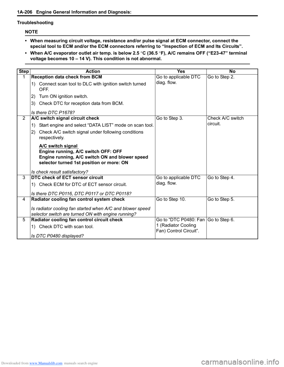
Step Action YesNo
1 Reception data check from BCM
1) Connect scan tool to DLC with ignition switch turned
OFF.
2) Turn ON ignition switch.
3) Check DTC for reception data from BCM.
Is there DTC P1678? Go to applicable DTC
diag. flow.
Go to Step 2.
2 A/C switch signal circuit check
1) Start engine and select “DATA LIST” mode on scan tool.
2) Check A/C switch signal under following conditions
respectively.
A/C switch signal
Engine running, A/C switch OFF: OFF
Engine running, A/C switch ON and blower speed
selector turned 1st position or more: ON
Is check result satisfactory? Go to Step 3. Check A/C switch
circuit.
3 DTC check of ECT sensor circuit
1) Check ECM for DTC of ECT sensor circuit.
Is there DTC P0116, DTC P0117 or DTC P0118? Go to applicable DTC
diag. flow.
Go to Step 4.
4 Radiator cooling fan control system check
Is radiator cooling fan started when A/C and blower speed
selector switch are turned ON with engine running? Go to Step 10. Go to Step 5.
5 Radiator cooling fan control circuit check
1) Check DTC with scan tool.
Is DTC P0480 displayed? Go to “DTC P0480: Fan
1 (Radiator Cooling
Fan) Control Circuit”.
Go to Step 6.
Page 277 of 1496

Downloaded from www.Manualslib.com manuals search engine Engine Electrical Devices: 1C-5
Electric Throttle Body System CalibrationS7RS0B1306004
NOTE
If working the service described under the
“Precautions of Electric Throttle Body
System Calibration in Section 1A” perform
following steps for electric throttle body
system calibration.
1) If electric throttle body assembly and/or APP sensor
assembly are replaced, perform following steps.
a) Disconnect negative cable at battery for 20 seconds or more for the purpose of clearing
calibration data of closed throttle position from
memory in ECM.
b) Connect negative cable to battery.
2) Keep ignition switch at ON position for 5 seconds or more without running engine.
APP Sensor Assembly On-Vehicle InspectionS7RS0B1306005
1) Check that APP sensor a ssembly has been mounted
to vehicle body properly (no pinched floor carpet,
etc.).
If mounting is not pro perly, reinstall APP sensor
assembly properly refe rring to “APP Sensor
Assembly Removal and Installation”.
2) Connect scan tool to DLC with ignition switch turned OFF.
3) Turn ON ignition switch and select “Data List” mode on scan tool.
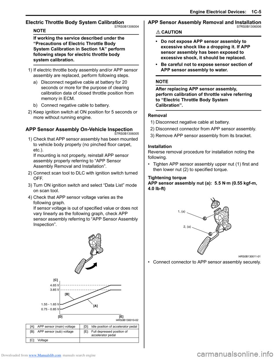
4) Check that APP sensor voltage varies as the following graph.
If sensor voltage is out of specified value or does not
vary linearly as the fo llowing graph, check APP
sensor assembly referring to “APP Sensor Assembly
Inspection”.
APP Sensor Assembly Removal and InstallationS7RS0B1306006
CAUTION!
• Do not expose APP sensor assembly to
excessive shock like a dropping it. If APP
sensor assembly has been exposed to
excessive shock, it should be replaced.
• Be careful not to expose sensor section of APP sensor assembly to water.
NOTE
After replacing APP sensor assembly,
perform calibration of th rottle valve referring
to “Electric Throttle Body System
Calibration”.
Removal
1) Disconnect negative cable at battery.
2) Disconnect connector from APP sensor assembly.
3) Remove APP sensor asse mbly from its bracket.
Installation
Reverse removal procedure for installation noting the
following.
• Tighten APP sensor assembly upper nut (1) first and then lower nut (2) to specified torque.
Tightening torque
APP sensor assembly nut (a): 5.5 N·m (0.55 kgf-m,
4.0 lb-ft)
• Connect connector to APP sensor assembly securely.
[A]: APP sensor (main) voltage [D]: Idle position of accelerator pedal
[B]: APP sensor (sub) voltage [E]: Full depressed position of
accelerator pedal
[C]: Voltage
[C]
[B]
[D] [E] [A]
4.65 V
3.85 V
1.55 - 1.65 V
0.75 - 0.85 V
I4RS0B130010-02
1, (a)
2, (a)
I4RS0B130011-01
Page 291 of 1496

Downloaded from www.Manualslib.com manuals search engine Engine Mechanical: 1D-6
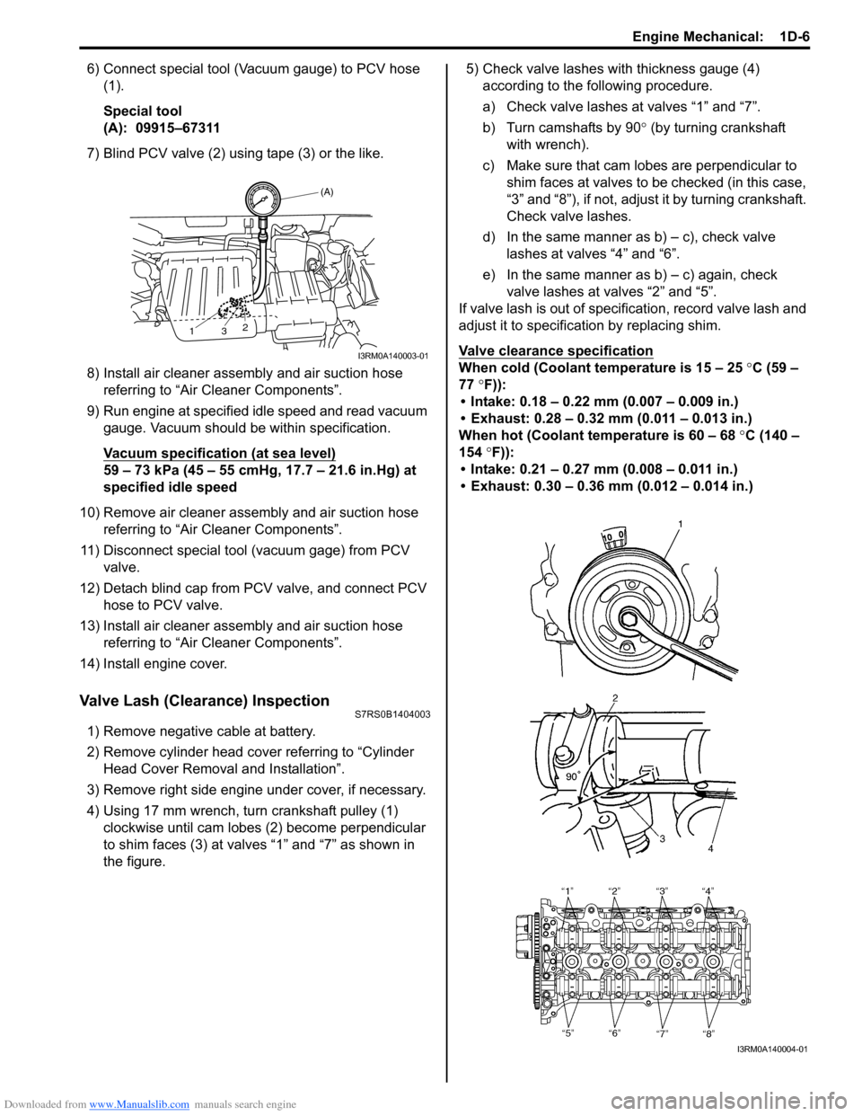
6) Connect special tool (Vacuum gauge) to PCV hose (1).
Special tool
(A): 09915–67311
7) Blind PCV valve (2) using tape (3) or the like.
8) Install air cleaner assembly and air suction hose referring to “Air Cleaner Components”.
9) Run engine at specified idle speed and read vacuum gauge. Vacuum should be within specification.
Vacuum specification (at sea level)
59 – 73 kPa (45 – 55 cmHg, 17.7 – 21.6 in.Hg) at
specified idle speed
10) Remove air cleaner assembly and air suction hose referring to “Air Cleaner Components”.
11) Disconnect special tool (vacuum gage) from PCV valve.
12) Detach blind cap from PCV valve, and connect PCV hose to PCV valve.
13) Install air cleaner assembly and air suction hose referring to “Air Cleaner Components”.
14) Install engine cover.
Valve Lash (Clearance) InspectionS7RS0B1404003
1) Remove negative cable at battery.
2) Remove cylinder head cover referring to “Cylinder Head Cover Removal and Installation”.
3) Remove right side engine under cover, if necessary.
4) Using 17 mm wrench, turn crankshaft pulley (1) clockwise until cam lobes (2) become perpendicular
to shim faces (3) at valves “1” and “7” as shown in
the figure. 5) Check valve lashes with thickness gauge (4)
according to the following procedure.
a) Check valve lashes at valves “1” and “7”.
b) Turn camshafts by 90 ° (by turning crankshaft
with wrench).
c) Make sure that cam lobes are perpendicular to shim faces at valves to be checked (in this case,
“3” and “8”), if not, adjust it by turning crankshaft.
Check valve lashes.
d) In the same manner as b) – c), check valve
lashes at valves “4” and “6”.
e) In the same manner as b) – c) again, check valve lashes at valves “2” and “5”.
If valve lash is out of specification, record valve lash and
adjust it to specification by replacing shim.
Valve clearance specification
When cold (Coolant te mperature is 15 – 25 °C (59 –
77 °F)):
• Intake: 0.18 – 0.22 mm (0.007 – 0.009 in.)
• Exhaust: 0.28 – 0.32 mm (0.011 – 0.013 in.)
When hot (Coolant temperature is 60 – 68 °C (140 –
154 °F)):
• Intake: 0.21 – 0.27 mm (0.008 – 0.011 in.)
• Exhaust: 0.30 – 0.36 mm (0.012 – 0.014 in.)
(A)
13 2
I3RM0A140003-01
I3RM0A140004-01
Page 326 of 1496

Downloaded from www.Manualslib.com manuals search engine 1D-41 Engine Mechanical:
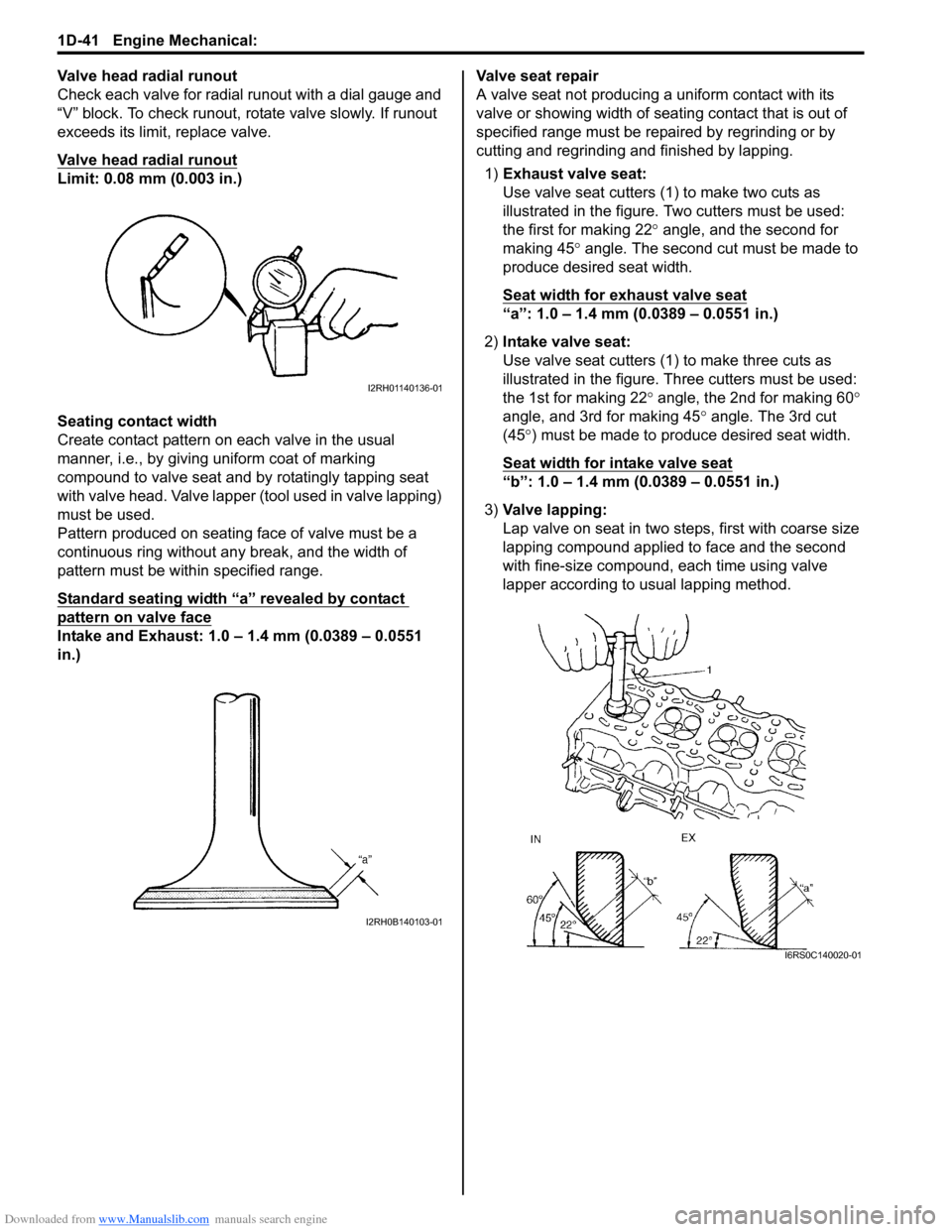
Valve head radial runout
Check each valve for radial runout with a dial gauge and
“V” block. To check runout, rotate valve slowly. If runout
exceeds its limit, replace valve.
Valve head radial runout
Limit: 0.08 mm (0.003 in.)
Seating contact width
Create contact pattern on each valve in the usual
manner, i.e., by giving uniform coat of marking
compound to valve seat and by rotatingly tapping seat
with valve head. Valve lapper (tool used in valve lapping)
must be used.
Pattern produced on seating face of valve must be a
continuous ring without any break, and the width of
pattern must be within specified range.
Standard seating width “a” revealed by contact
pattern on valve face
Intake and Exhaust: 1.0 – 1.4 mm (0.0389 – 0.0551
in.)Valve seat repair
A valve seat not producing
a uniform contact with its
valve or showing width of seating contact that is out of
specified range must be repaired by regrinding or by
cutting and regrinding and finished by lapping.
1) Exhaust valve seat:
Use valve seat cutters (1 ) to make two cuts as
illustrated in the figure. Two cutters must be used:
the first for making 22 ° angle, and the second for
making 45 ° angle. The second cut must be made to
produce desired seat width.
Seat width for exhaust valve seat
“a”: 1.0 – 1.4 mm (0.0389 – 0.0551 in.)
2) Intake valve seat:
Use valve seat cutters (1) to make three cuts as
illustrated in the figure. Th ree cutters must be used:
the 1st for making 22 ° angle, the 2nd for making 60 °
angle, and 3rd for making 45 ° angle. The 3rd cut
(45 °) must be made to produce desired seat width.
Seat width for intake valve seat
“b”: 1.0 – 1.4 mm (0.0389 – 0.0551 in.)
3) Valve lapping:
Lap valve on seat in two steps, first with coarse size
lapping compound applied to face and the second
with fine-size compound, each time using valve
lapper according to usual lapping method.
I2RH01140136-01
I2RH0B140103-01
I6RS0C140020-01