Page 1362 of 1496
Downloaded from www.Manualslib.com manuals search engine 9F-16 Security and Locks:
Specifications
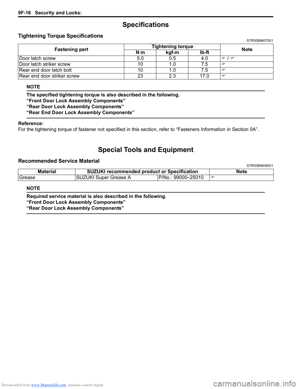
Tightening Torque SpecificationsS7RS0B9607001
NOTE
The specified tightening torque is also described in the following.
“Front Door Lock Assembly Components”
“Rear Door Lock Assembly Components”
“Rear End Door Lock Assembly Components”
Reference:
For the tightening torque of fastener not specified in this section, refer to “Fasteners Information in Section 0A”.
Special Tools and Equipment
Recommended Service MaterialS7RS0B9608001
NOTE
Required service material is also described in the following.
“Front Door Lock Assembly Components”
“Rear Door Lock Assembly Components”
Fastening part Tightening torque
Note
N ⋅mkgf-mlb-ft
Door latch screw 5.0 0.5 4.0 �) / �)
Door latch striker screw 10 1.0 7.5 �)
Rear end door latch bolt 10 1.0 7.5 �)
Rear end door striker screw 23 2.3 17.0 �)
MaterialSUZUKI recommended product or Specification Note
Grease SUZUKI Super Grease A P/No.: 99000–25010�)
Page 1363 of 1496
Downloaded from www.Manualslib.com manuals search engine Seats: 9G-1
Body, Cab and Accessories
Seats
Repair Instructions
Front Seat ComponentsS7RS0B9706001
2
4
1 3
11
6
3
4
6
7
8
(b)
(b)
10
5
(a)
or
94
5
(c)
(b)
10
or
A
A
B
AB
B
A
I6RS0C970001-02
1. Seat cushion 6. Knob or 11. Riser bolt
: Apply thread lock 99000-32100 or 99000-32030
to all around thread part of bolt.
2. Seat back 7. Side air bag module (if equipped) : 23 N⋅m (2.3 kgf-m, 17.0 lb-ft)
3. Riser nut 8. Side air bag harness (if equipped) : 35 N⋅m (3.5 kgf-m, 25.5 lb-ft)
4. Cover or 9. Seat mounting bolt
: Apply thread lock 99000-32100 or 99000-
32030 to all around thread part of bolt. :28 N
⋅m (2.8 kgf-m, 20.5 lb-ft) (Seat lifter type)
35 N ⋅m (3.5 kgf-m, 25.5 lb-ft) (Non seat lifter
type)
5. Seat adjuster 10. Seat back mounting bolt
Page 1364 of 1496
Downloaded from www.Manualslib.com manuals search engine 9G-2 Seats:
Front Seat Removal and InstallationS7RS0B9706002
WARNING!
Refer to “Air Bag Warning in Section 00” before starting service work.
Removal1) Disable air bag system referring to “Disabling Air Bag System in Section 8B”.
2) Disconnect couplers for seat harness and side air bag, if equipped.
3) Remove 4 mounting bolts to remove seat assembly.
4) Disassemble and repair seat if necessary.
Installation
Reverse removal procedure to install front seat.
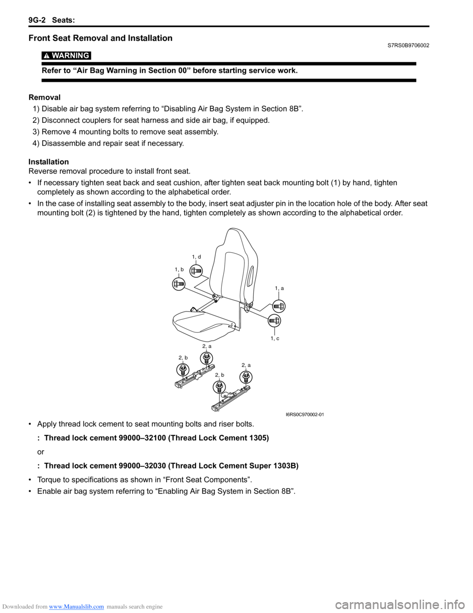
• If necessary tighten seat back and seat cushion, after tighten seat back mounting bolt (1) by hand, tighten completely as shown according to the alphabetical order.
• In the case of installing seat assembly to the body, insert se at adjuster pin in the location hole of the body. After seat
mounting bolt (2) is tightened by t he hand, tighten completely as shown according to the alphabetical order.
• Apply thread lock cement to seat mounting bolts and riser bolts. : Thread lock cement 99000–32100 (Thread Lock Cement 1305)
or
: Thread lock cement 99000–32030 (Thread Lock Cement Super 1303B)
• Torque to specifications as shown in “Front Seat Components”.
• Enable air bag system referring to “Enabling Air Bag System in Section 8B”.
1, d
1, b
1, a
1, c
2, a
2, b2, a
2, b
I6RS0C970002-01
Page 1365 of 1496
Downloaded from www.Manualslib.com manuals search engine Seats: 9G-3
Rear Seat ComponentsS7RS0B9706003
1
5
(b)
(b)
(b)
8
7
9
2
4
4
3
(b)
6
6(c)
2
3
10
6
(a)
10
11
12
“1”
“2”
“3”
I7RS0A970001-01
1. Rear seat cushion
6. Rear seat center hinge11. Seat cushion hook
2. Rear seat back right 7. Seat hinge bracket12. Seat back striker mounting bolt
:Tightening order (Right side): “1” →“2” →“3”
:Tightening order (Left side): “2 →“1” →“3”
3. Rear seat back left 8. Rear seat belt buckle : 23 N⋅m (2.3 kgf-m, 17.0 lb-ft)
4. Head rest 9. Seat back striker : 43 N⋅m (4.3 kgf-m, 31.5 lb-ft)
5. Child anchorage bracket 10. Seat cushion insert wire : 10 N⋅m (1.0 kgf-m, 7.5 lb-ft)
Page 1366 of 1496
Downloaded from www.Manualslib.com manuals search engine 9G-4 Seats:
Rear Seat Removal and InstallationS7RS0B9706004
Removal1) Fold rear seat back forward.
2) Remove seat mounting bolts and nuts to remove seat assembly.
3) Disassemble and repair seat as necessary.
Installation
Reverse removal procedure to install rear seat.
• Tighten seat back striker mounting bolts according to “Rear Seat Components”.
• Torque to specifications in “Rear Seat Components”.
• When installing seat cushion, align seat cushion hook with center hinge bracket.
Specifications
Tightening Torque SpecificationsS7RS0B9707001
NOTE
The specified tightening torque is also described in the following.
“Front Seat Components”
“Rear Seat Components”
Reference:
For the tightening torque of fastener not specified in this section, refer to “Fasteners Information in Section 0A”.
Special Tools and Equipment
Recommended Service MaterialS7RS0B9708001
NOTE
Required service material is also described in the following.
“Front Seat Components”
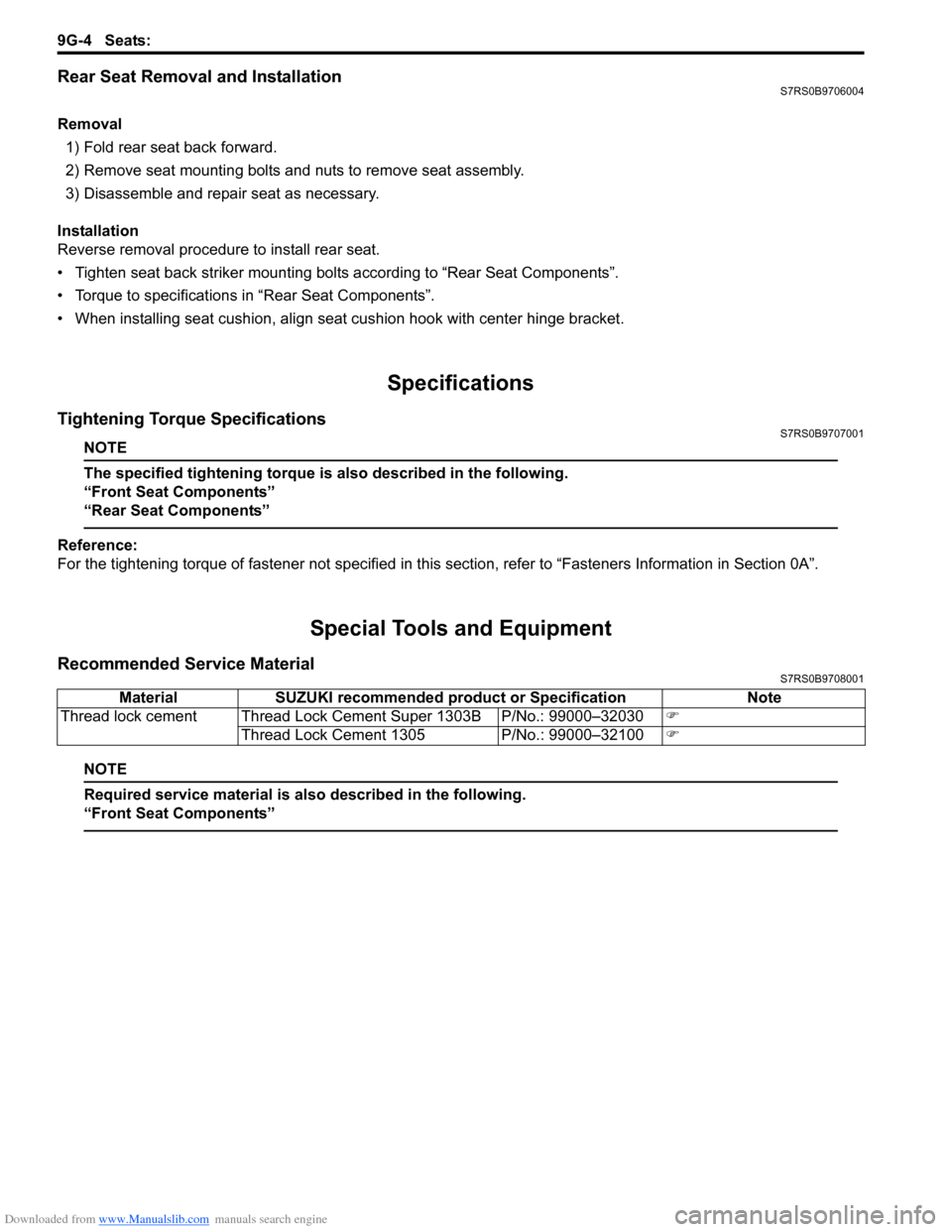
Material SUZUKI recommended product or Specification Note
Thread lock cement Thread Lock Cement Super 1303B P/No.: 99000–32030 �)
Thread Lock Cement 1305 P/No.: 99000–32100 �)
Page 1369 of 1496
Downloaded from www.Manualslib.com manuals search engine Interior Trim: 9H-3
Specifications
Tightening Torque SpecificationsS7RS0B9807001
Reference:
For the tightening torque of fastener not specified in this section, refer to “Fasteners Information in Section 0A”.
Fastening part
Tightening torque
Note
N ⋅mkgf-mlb-ft
Sun visor screw 40.4 3.0 �)
Page 1377 of 1496
Downloaded from www.Manualslib.com manuals search engine Hood / Fenders / Doors: 9J-8
Specifications
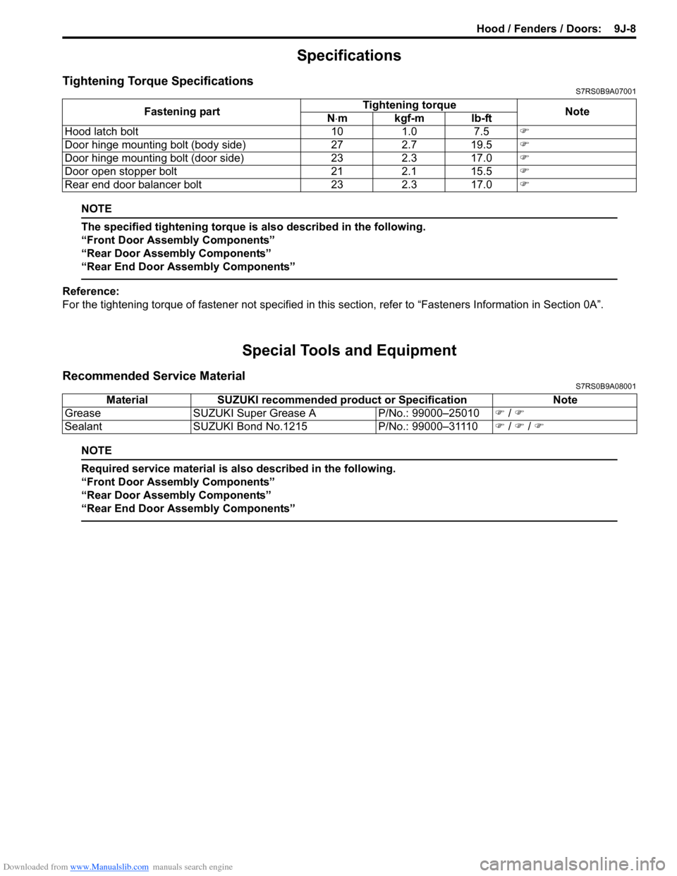
Tightening Torque SpecificationsS7RS0B9A07001
NOTE
The specified tightening torque is also described in the following.
“Front Door Assembly Components”
“Rear Door Assembly Components”
“Rear End Door Assembly Components”
Reference:
For the tightening torque of fastener not specified in this section, refer to “Fasteners Information in Section 0A”.
Special Tools and Equipment
Recommended Service MaterialS7RS0B9A08001
NOTE
Required service material is also described in the following.
“Front Door Assembly Components”
“Rear Door Assembly Components”
“Rear End Door Assembly Components”
Fastening part Tightening torque
Note
N ⋅mkgf-mlb-ft
Hood latch bolt 10 1.0 7.5 �)
Door hinge mounting bolt (body side) 27 2.7 19.5 �)
Door hinge mounting bolt (door side) 23 2.3 17.0 �)
Door open stopper bolt 21 2.1 15.5 �)
Rear end door balancer bolt 23 2.3 17.0 �)
MaterialSUZUKI recommended product or Specification Note
Grease SUZUKI Super Grease A P/No.: 99000–25010�) / �)
Sealant SUZUKI Bond No.1215 P/No.: 99000–31110�) / �) / �)
Page 1380 of 1496
Downloaded from www.Manualslib.com manuals search engine 9K-3 Body Structure:
Specifications
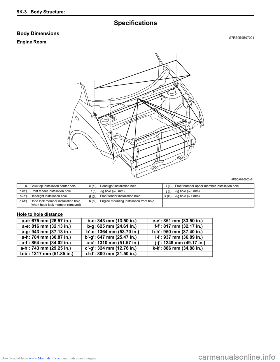
Body DimensionsS7RS0B9B07001
Engine Room
Hole to hole distance
g’
b
ckg
i
a
b’
c’
d
d’
e
e’
f’
f
h
h’
i’ j
k’
j’
I4RS0A9B0003-01
a. Cowl top installation center hole e (e’). Headlight installation hole i (i’). Front bumper upper member installation hole
b (b’). Front fender installation hole f (f’). Jig hole (φ 8 mm) j (j’). Jig hole (φ 8 mm)
c (c’). Headlight installation hole g (g’). Front fender installation hole k (k’). Jig hole (φ 7 mm)
d (d’). Hood lock member installation hole (when hood lock member removed) h (h’). Engine mounting installation front hole
a-d: 675 mm (26.57 in.) b-c: 343 mm (13.50 in.) e-e’: 851 mm (33.50 in.)
a-e: 816 mm (32.13 in.) b-g: 625 mm (24.61 in.) f-f’: 817 mm (32.17 in.)
a-g: 943 mm (37.13 in.) b’-c: 1364 mm (53.70 in.) h-h’: 950 mm (37.40 in.)
a-h: 784 mm (30.87 in.) b’-g’: 647 mm (25.47 in.) i-i’: 937 mm (36.89 in.)
a-f’: 864 mm (34.02 in.) c-c’: 1310 mm (51.57 in.) j-j’: 1249 mm (49.17 in.)
a-h’: 743 mm (29.25 in.) c’-g’: 324 mm (12.76 in.) k-k’: 886 mm (34.88 in.)
b-b’: 1317 mm (51.85 in.) d-d’: 800 mm (31.50 in.)