2006 SUZUKI SWIFT wheel nut
[x] Cancel search: wheel nutPage 538 of 1496
Downloaded from www.Manualslib.com manuals search engine 4D-3 Parking Brake:
6) Release parking brake lever and then make sure that there is no drag in rear wheel.
If there is, repeats go to step 2).
7) Make sure that the number of notch is between 4 and 9 when operating parking brake lever.
8) If the number of notch is not between 4 and 9, replace parking brake cable and/or inspect rear
brake caliper.
Parking brake stroke
When lever is pulled up at 200 N (20kg, 44lbs) : 4
to 9 notches
Parking Brake Cable Removal and InstallationS7RS0B4406002
Removal
NOTE
When it is necessary to remove both right
and left parking brake cables, repeat below
steps 2) and 5) on right and left wheels.
1) Hoist vehicle.
2) Remove wheel.
3) Disconnect parking brake cable from equalizer (parking brake lever) and clamps.
4) Disconnect parking brake cable from lever referring to “Rear Disc Brake Caliper Removal and Installation
in Section 4C”.
5) Remove parking brake cable and parking cable bracket.
Installation
Install it by reversing removal procedure, noting the
following points.
• Install clamps properly referring to “Parking Brake Cable Construction”.
• Tighten bolts and nuts to specified torque referring to “Parking Brake Cable Construction”.
Tightening torque
Parking brake lever bolt: 25 N·m (2.5 kgf-m, 18.0
lb-ft)
Parking cable clamp bolt: 11 N·m (1.1 kgf-m, 8.0
lb-ft)
Parking cable bracket bolt: 25 N·m (2.5 kgf-m,
18.0 lb-ft)
• Adjust parking brake cable. Refer to “Parking Brake Inspection and Adjustment”.
• Check brake disc for dragging and brake system for proper performance. Brake test should be performed.
Parking Brake Lever Removal and InstallationS7RS0B4406003
Removal
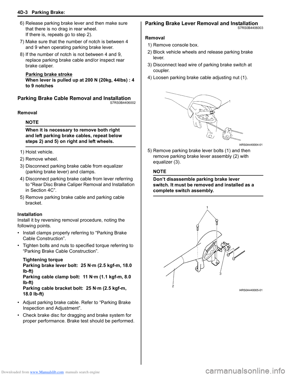
1) Remove console box.
2) Block vehicle wheels and release parking brake lever.
3) Disconnect lead wire of parking brake switch at coupler.
4) Loosen parking brake cable adjusting nut (1).
5) Remove parking brake lever bolts (1) and then remove parking brake lever assembly (2) with
equalizer (3).
NOTE
Don’t disassemble parking brake lever
switch. It must be removed and installed as a
complete switch assembly.
I4RS0A440004-01
I4RS0A440005-01
Page 574 of 1496
Downloaded from www.Manualslib.com manuals search engine 4E-35 ABS:
Specifications
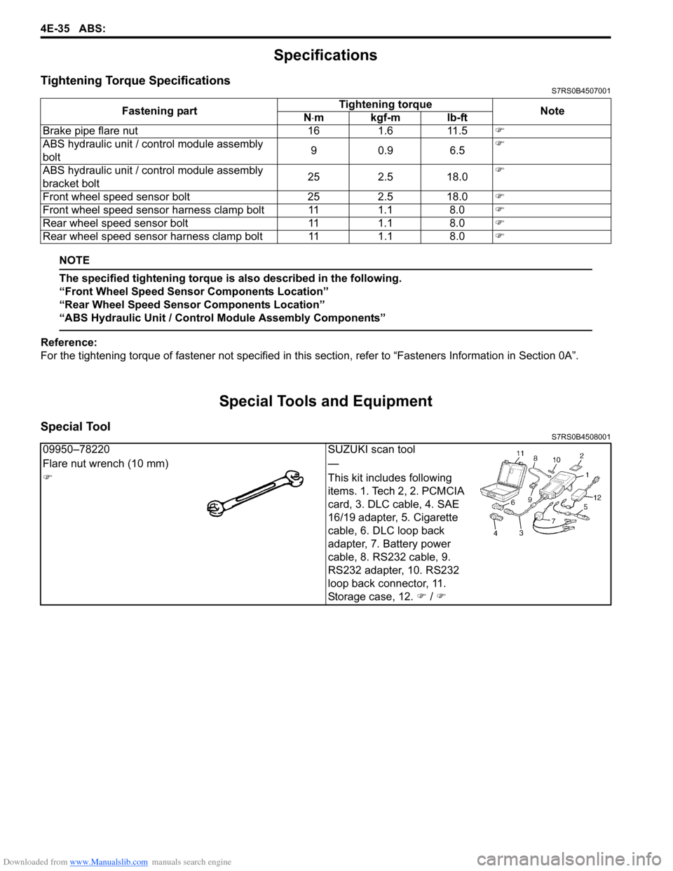
Tightening Torque SpecificationsS7RS0B4507001
NOTE
The specified tightening torque is also described in the following.
“Front Wheel Speed Sensor Components Location”
“Rear Wheel Speed Sensor Components Location”
“ABS Hydraulic Unit / Control Module Assembly Components”
Reference:
For the tightening torque of fastener not specified in this section, refer to “Fasteners Information in Section 0A”.
Special Tools and Equipment
Special ToolS7RS0B4508001
Fastening part Tightening torque
Note
N ⋅mkgf-mlb-ft
Brake pipe flare nut 16 1.6 11.5 �)
ABS hydraulic unit / c ontrol module assembly
bolt 90.9 6.5�)
ABS hydraulic unit / c ontrol module assembly
bracket bolt 25 2.5 18.0�)
Front wheel speed sensor bolt 25 2.5 18.0 �)
Front wheel speed sensor harness clamp bolt 11 1.1 8.0 �)
Rear wheel speed sensor bolt 11 1.1 8.0 �)
Rear wheel speed sensor har ness clamp bolt 11 1.1 8.0 �)
09950–78220SUZUKI scan tool
Flare nut wrench (10 mm) —
�) This kit includes following
items. 1. Tech 2, 2. PCMCIA
card, 3. DLC cable, 4. SAE
16/19 adapter, 5. Cigarette
cable, 6. DLC loop back
adapter, 7. Battery power
cable, 8. RS232 cable, 9.
RS232 adapter, 10. RS232
loop back connector, 11.
Storage case, 12. �) / �)
Page 631 of 1496

Downloaded from www.Manualslib.com manuals search engine Electronic Stability Program: 4F-57
3) Remove front brake pipe referring to “Front Brake Hose / Pipe Removal and In stallation in Section 4A”.
4) Remove ESP ® hydraulic unit / control module with
bracket from vehicle by removing bracket bolts.
5) Remove bolt (4) and pull out ESP ® hydraulic unit /
control module assembly (1) from bracket (3) using
flat end rod or the like (2).
Installation 1) Install hydraulic unit / co ntrol module assembly and
by reversing removal procedure.
Tightening torque
Brake pipe flare nut: 16 N·m (1.6 kgf-m, 11.5 lb-
ft)
ESP ® hydraulic unit / control module assembly
bolt: 9 N·m (0.9 kgf-m, 6.5 lb-ft)
ESP ® hydraulic unit / control module assembly
bracket bolt: 25 N·m (2.5 kgf-m, 18.0 lb-ft)
2) Bleed air from brake system referring to “Air Bleeding of Brake System in Section 4A”.
3) Check each installed part for fluid leakage.
4) Connect SUZUKI Scan Tool.
5) Turn ignition switch to ON position. And SLIP indicator lamp flush. (Other than replace with new
one) If other than SLIP indicator lamp light, check
DTC and repair it.
6) Turn ignition switch to ON position. And ESP®
warning lamp, SLIP indicator lamp, ESP ® OFF
lamp, Brake warning lamp lights and ABS warning
lamp flush. (Replace new one)
7) Check DTC.
NOTE
If any DTC(s) other than C1075, C1076 or
C1078 are detected, sensor calibration can
not be completed. Repair the detected it(s)
first.
8) Perform “Sensor Calibration”.
9) Perform “ESP ® Hydraulic Unit Operation Check”.
10) Turn ignition switch to OFF position once and then
ON position. In this state, make sure that indicator
light and warning light turns off.
11) Check DTC(s) are not stored in hydraulic unit / control module.
Front / Rear Wheel Speed Sensor On-Vehicle
Inspection
S7RS0B4606028
CAUTION!
Incorrect voltage and/or wrong connection
cause damage to wheel speed sensor.
Output Voltage Inspection
1) Disconnect negative (–) cable from battery.
2) Hoist vehicle a little.
3) Disconnect wheel speed sensor connector.
4) Disconnect wheel speed grommet from vehicle body.
5) Set up measuring devices as shown in figure, the resistance to 115 Ω and the power supply voltage
to12 V.
4
1
2 3
I6RS0B460030-02
[A]: Front wheel speed sensor 3. “WHT” wire terminal
[B]: Rear wheel speed sensor 4. “BLK” wire terminal
1. Wheel speed sensor connector 5. Power supply (12 V)
2. Resistance (115 Ω)
V
2
5
4 1
3
43
1
[A]
[B]
I6RS0B460031-02
Page 640 of 1496

Downloaded from www.Manualslib.com manuals search engine 4F-66 Electronic Stability Program:
Specifications
Tightening Torque SpecificationsS7RS0B4607001
Reference:
For the tightening torque of fastener not specified in this section, refer to “Fasteners Information in Section 0A”.
NOTE
The specified tightening torque is also described in the following.
“ESP® Hydraulic Unit / Control Module Assembly Removal and Installation”
Special Tools and Equipment
Special ToolS7RS0B4608001
Fastening part Tightening torque
Note
N ⋅mkgf-mlb-ft
Brake pipe flare nut 16 1.6 11.5 �)
ESP ® hydraulic unit / control module assembly
bolt 90.9 6.5�)
ESP ® hydraulic unit / control module assembly
bracket bolt 25 2.5 18.0�)
Front wheel speed sensor bolt 11 1.1 8.0 �)
Front wheel speed sensor harness clamp bolt 11 1.1 8.0 �)
Rear wheel speed sensor bolt 11 1.1 8.0 �)
Rear wheel speed sensor har ness clamp bolt 11 1.1 8.0 �)
Yaw rate / G sensor assembly nut 8 0.8 6.0 �)
09956–02311SUZUKI scan tool
Brake pressure gauge —
�) This kit includes following
items. 1. Tech 2, 2. PCMCIA
card, 3. DLC cable, 4. SAE
16/19 adapter, 5. Cigarette
cable, 6. DLC loop back
adapter, 7. Battery power
cable, 8. RS232 cable, 9.
RS232 adapter, 10. RS232
loop back connector, 11.
Storage case, 12.�) / �) / �) /
�) / �) / �) / �)
Page 674 of 1496
Downloaded from www.Manualslib.com manuals search engine 5A-30 Automatic Transmission/Transaxle:
Troubleshooting
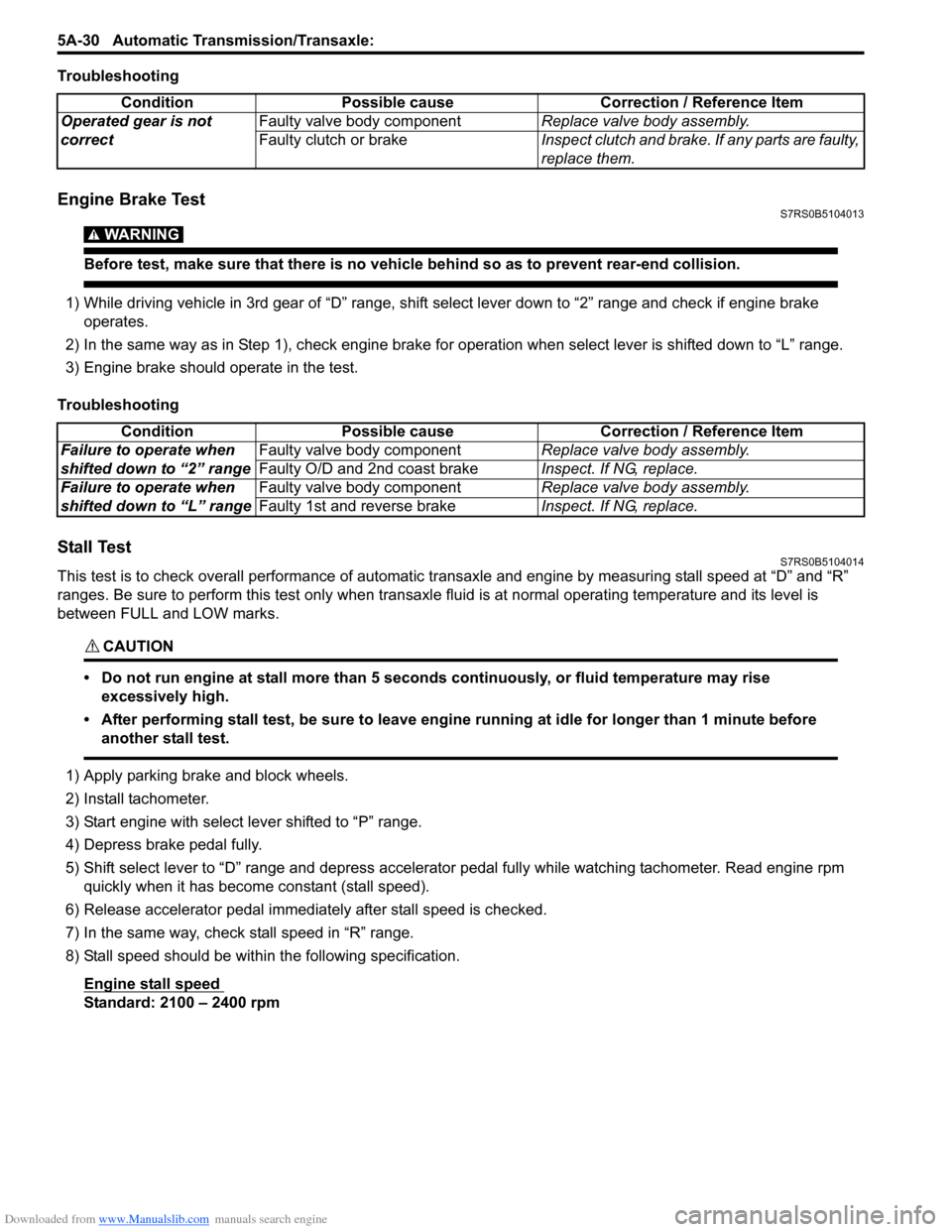
Engine Brake TestS7RS0B5104013
WARNING!
Before test, make sure that there is no vehicle behind so as to prevent rear-end collision.
1) While driving vehicle in 3rd gear of “D” range, shift select lever down to “2” range and check if engine brake
operates.
2) In the same way as in Step 1), check engine brake for operation when select lever is shifted down to “L” range.
3) Engine brake should operate in the test.
Troubleshooting
Stall TestS7RS0B5104014
This test is to check overall performance of automatic tr ansaxle and engine by measuring stall speed at “D” and “R”
ranges. Be sure to perform this test only when transaxle fluid is at normal operating temperature and its level is
between FULL and LOW marks.
CAUTION!
• Do not run engine at stall more than 5 seconds continuously, or fluid temperature may rise excessively high.
• After performing stall test, be su re to leave engine running at idle for longer than 1 minute before
another stall test.
1) Apply parking brake and block wheels.
2) Install tachometer.
3) Start engine with select lever shifted to “P” range.
4) Depress brake pedal fully.
5) Shift select lever to “D” range and depress accelerator pedal fully while watching tachometer. Read engine rpm quickly when it has become constant (stall speed).
6) Release accelerator pedal immediately after stall speed is checked.
7) In the same way, check stall speed in “R” range.
8) Stall speed should be withi n the following specification.
Engine stall speed
Standard: 2100 – 2400 rpm Condition Possible cause Correction / Reference Item
Operated gear is not
correct Faulty valve body component
Replace valve body assembly.
Faulty clutch or brake Inspect clutch and brake. If any parts are faulty,
replace them.
Condition Possible cause Correction / Reference Item
Failure to operate when
shifted down to “2” range Faulty valve body component
Replace valve body assembly.
Faulty O/D and 2nd coast brake Inspect. If NG, replace.
Failure to operate when
shifted down to “L” range Faulty valve body component
Replace valve body assembly.
Faulty 1st and reverse brake Inspect. If NG, replace.
Page 675 of 1496
Downloaded from www.Manualslib.com manuals search engine Automatic Transmission/Transaxle: 5A-31
Troubleshooting
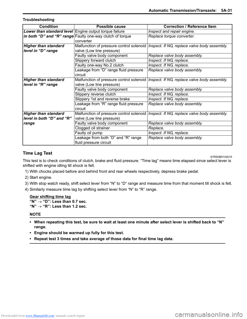
Time Lag TestS7RS0B5104015
This test is to check conditions of clutch, brake and fluid pressure. “Time lag” means time elapsed since select lever is
shifted with engine idling till shock is felt.
1) With chocks placed before and behind front and rear wheels respectively, depress brake pedal.
2) Start engine.
3) With stop watch ready, shift select lever from “N” to “D” range an d measure time from that moment till shock is felt.
4) Similarly measure time lag by shifting select lever from “N” to “R” range.
Gear shifting time lag
“N” → “D”: Less than 0.7 sec.
“N” → “R”: Less than 1.2 sec.
NOTE
• When repeating this test, be sure to wait at least one minute after select lever is shifted back to “N”
range.
• Engine should be warmed up fully for this test.
• Repeat test 3 times and take average of those data for final time lag data.
Condition Possible cause Correction / Reference Item
Lower than standard level
in both “D” and “R” range Engine output torque failure
Inspect and repair engine.
Faulty one-way clutch of torque
converter Replace torque converter.
Higher than standard
level in “D” range Malfunction of pressure control solenoid
valve (Low line pressure) Inspect. If NG, replace valve body assembly.
Faulty valve body component Replace valve body assembly.
Slippery forward clutch Inspect. If NG, replace.
Faulty one-way No.2 clutch Inspect. If NG, replace.
Leakage from “D” range fluid pressure
circuit Replace valve body assembly.
Higher than standard
level in “R” range Malfunction of pressure control solenoid
valve (Low line pressure) Inspect. If NG, replace valve body assembly.
Faulty valve body component Replace valve body assembly.
Slippery reverse clutch Inspect. If NG, replace.
Slippery 1st and reverse brake Inspect. If NG, replace.
Leakage from “R” range fluid pressure
circuit Replace valve body assembly.
Higher than standard
level in both “D” and “R”
range Malfunction of pressure control solenoid
valve (Low line pressure)
Inspect. If NG, replace valve body assembly.
Faulty valve body component Replace valve body assembly.
Clogged oil strainer Replace.
Faulty oil pump Inspect. If NG, replace.
Leakage from both “D” and “R” range
fluid pressure circuit Replace valve body assembly.
Page 676 of 1496
Downloaded from www.Manualslib.com manuals search engine 5A-32 Automatic Transmission/Transaxle:
Troubleshooting
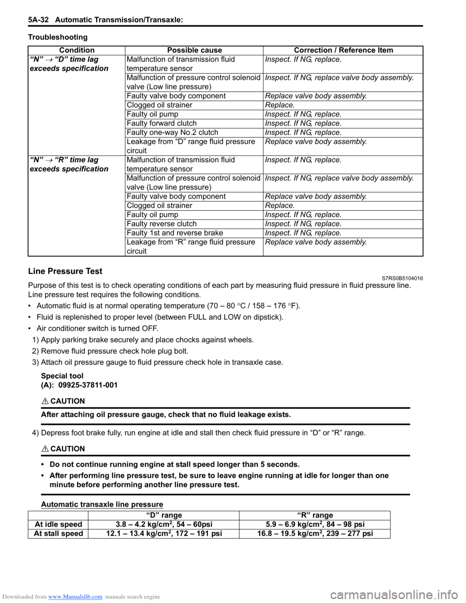
Line Pressure TestS7RS0B5104016
Purpose of this test is to check operat ing conditions of each part by measuring fluid pressure in fluid pressure line.
Line pressure test requires the following conditions.
• Automatic fluid is at normal operating temperature (70 – 80 °C / 158 – 176 °F).
• Fluid is replenished to proper level (between FULL and LOW on dipstick).
• Air conditioner switch is turned OFF.
1) Apply parking brake securely and place chocks against wheels.
2) Remove fluid pressure check hole plug bolt.
3) Attach oil pressure gauge to fluid pr essure check hole in transaxle case.
Special tool
(A): 09925-37811-001
CAUTION!
After attaching oil pressure gauge, check that no fluid leakage exists.
4) Depress foot brake fully, run engine at idle and stall then check fluid pressure in “D” or “R” range.
CAUTION!
• Do not continue running engine at stall speed longer than 5 seconds.
• After performing line pressure test, be sure to leave engine running at idle for longer than one minute before performing another line pressure test.
Automatic transaxle line pressure
Condition Possible cause Correction / Reference Item
“N”
→ “D” time lag
exceeds specification Malfunction of transmission fluid
temperature sensor Inspect. If NG, replace.
Malfunction of pressure control solenoid
valve (Low line pressure) Inspect. If NG, replace valve body assembly.
Faulty valve body component Replace valve body assembly.
Clogged oil strainer Replace.
Faulty oil pump Inspect. If NG, replace.
Faulty forward clutch Inspect. If NG, replace.
Faulty one-way No.2 clutch Inspect. If NG, replace.
Leakage from “D” range fluid pressure
circuit Replace valve body assembly.
“N”
→ “R” time lag
exceeds specification Malfunction of transmission fluid
temperature sensor Inspect. If NG, replace.
Malfunction of pressure control solenoid
valve (Low line pressure) Inspect. If NG, replace valve body assembly.
Faulty valve body component Replace valve body assembly.
Clogged oil strainer Replace.
Faulty oil pump Inspect. If NG, replace.
Faulty reverse clutch Inspect. If NG, replace.
Faulty 1st and reverse brake Inspect. If NG, replace.
Leakage from “R” range fluid pressure
circuit Replace valve body assembly.
“D” range
“R” range
At idle speed 3.8 – 4.2 kg/cm2, 54 – 60psi 5.9 – 6.9 kg/cm2, 84 – 98 psi
At stall speed 12.1 – 13.4 kg/cm2, 172 – 191 psi 16.8 – 19.5 kg/cm2, 239 – 277 psi
Page 854 of 1496

Downloaded from www.Manualslib.com manuals search engine 5C-2 Clutch:
Diagnostic Information and Procedures
Clutch System Symptom DiagnosisS7RS0B5304001
Repair Instructions
Clutch Pedal InspectionS7RS0B5306001
Cylinder Push Rod Play “A”1) Press clutch pedal (1) gradually with finger, stop when slight increase of resistance is felt and
measure how much pedal has moved (push rod
play) as represented by “A” as shown.
Push rod play
“A”: Max. 3 mm (0.12 in.)
2) If “A” is not within specification, replace master cylinder (3) or pedal arm (2). Clutch Pedal Free Travel “B”
1) Depress clutch pedal (1), stop the moment clutch resistance is felt, and measure how much pedal has
moved (clutch pedal free travel) as represented by
“B” in figure.
Clutch pedal free travel
“B”
: 2 – 8 mm (0.08 – 0.31 in.)
2) If “B” is not within specification, check pedal arm (2) and master cylinder (3) and replace defective part.
Condition Possible cause Correction / Reference Item
Slipping Improper clutch pedal free travel Replace master cylinder or clutch pedal arm.
Worn or oily clutch disc facing Replace disc.
Warped disc, pressure plate or flywheel
surface Replace disc, clutch cover or flywheel.
Weakened diaphragm spring Replace clutch cover.
Master cylinder piston or seal cup not
returning Replace master cylinder.
Dragging clutch Improper clutch pedal free travel Replace master cylinder or clutch pedal arm.
Weakened diaphragm spring, or worn
spring tip Replace clutch cover.
Rusted input shaft splines Lubricate.
Damaged or worn splines of transaxle
input shaft Replace input shaft.
Excessively wobbly clutch disc Replace disc.
Clutch facings broken or dirty with oil Replace disc.
Fluid leakage Repair or replace.
Clutch vibration Glazed (glass-like) clutch facings Repair or replace disc.
Clutch facings dirty with oil Replace disc.
Release bearing slides unsmoothly on
input shaft bearing retainer Lubricate or replace input shaft bearing
retainer.
Wobbly clutch disc, or poor facing
contact Replace disc.
Weakened torsion springs in clutch disc Replace disc.
Clutch disc rivets loose Replace disc.
Distorted pressure plate or flywheel
surface Replace clutch cover or flywheel.
Weakened engine mounting Replace engine mounting.
Loosened engine mounting bolt or nut Retighten engine mounting bolt or nut.
Noisy clutch Worn or broken release bearing Replace release bearing.
Input shaft front bearing worn down Replace input shaft bearing.
Excessive rattle of clutch disc hub Replace disc.
Cracked clutch disc Replace disc.
Pressure plate and diaphragm spring
rattling Replace clutch cover.
Grabbing clutch Clutch disc facings soaked with oil Replace disc.
Clutch disc facings excessively worn Replace disc.
Rivet heads showing out of facing Replace disc.
Weakened torsion springs Replace disc.