2006 SUZUKI SWIFT Engine block
[x] Cancel search: Engine blockPage 357 of 1496

Downloaded from www.Manualslib.com manuals search engine Engine Lubrication System: 1E-5
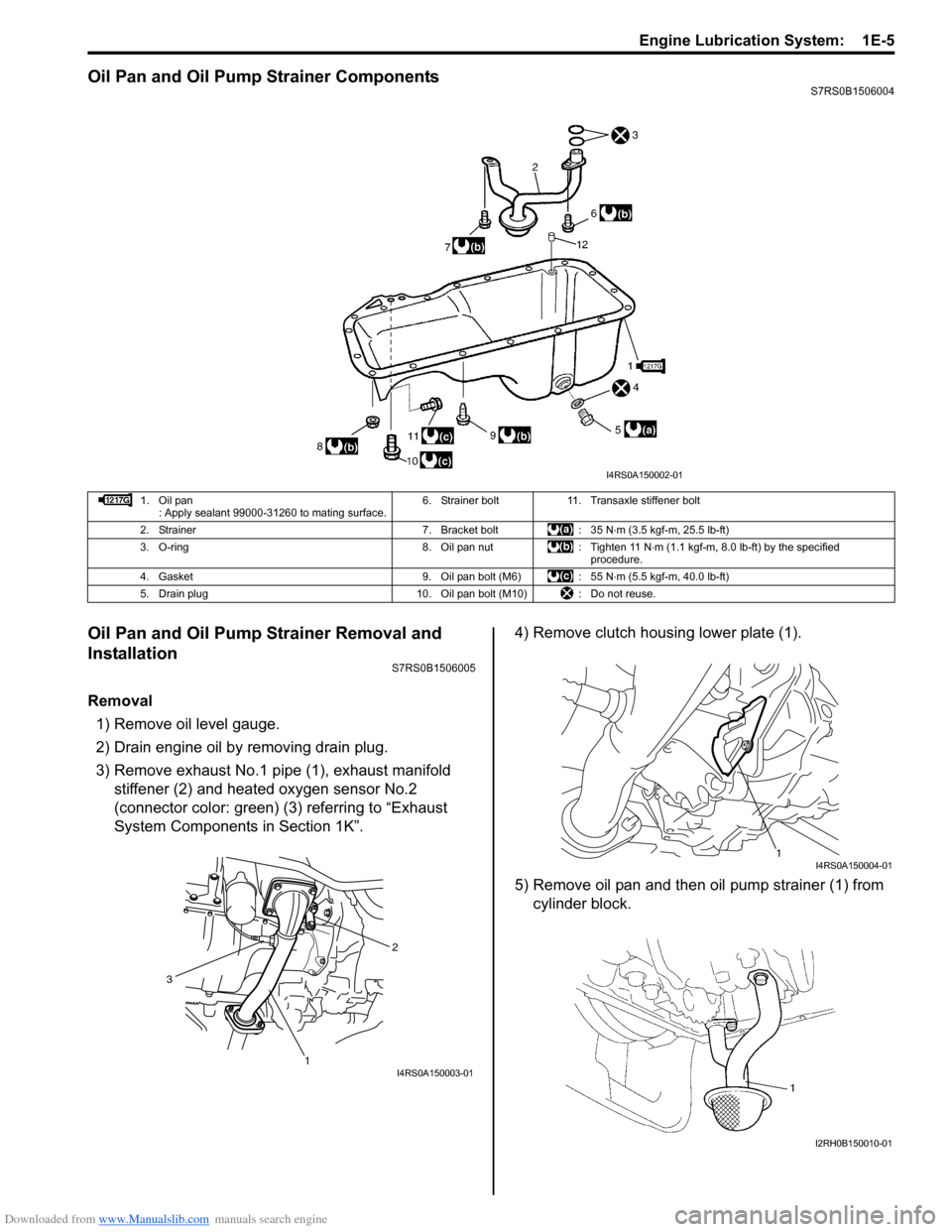
Oil Pan and Oil Pump Strainer ComponentsS7RS0B1506004
Oil Pan and Oil Pump Strainer Removal and
Installation
S7RS0B1506005
Removal1) Remove oil level gauge.
2) Drain engine oil by removing drain plug.
3) Remove exhaust No.1 pipe (1), exhaust manifold stiffener (2) and heated oxygen sensor No.2
(connector color: green) (3) referring to “Exhaust
System Components in Section 1K”. 4) Remove clutch housing lower plate (1).
5) Remove oil pan and then oil pump strainer (1) from
cylinder block.
I4RS0A150002-01
1. Oil pan : Apply sealant 99000-31260 to mating surface. 6. Strainer bolt 11. Transaxle stiffener bolt
2. Strainer 7. Bracket bolt : 35 N ⋅m (3.5 kgf-m, 25.5 lb-ft)
3. O-ring 8. Oil pan nut : Tighten 11 N ⋅m (1.1 kgf-m, 8.0 lb-ft) by the specified
procedure.
4. Gasket 9. Oil pan bolt (M6) : 55 N ⋅m (5.5 kgf-m, 40.0 lb-ft)
5. Drain plug 10. Oil pan bolt (M10) : Do not reuse.
2
1
3
I4RS0A150003-01
1I4RS0A150004-01
I2RH0B150010-01
Page 358 of 1496

Downloaded from www.Manualslib.com manuals search engine 1E-6 Engine Lubrication System:
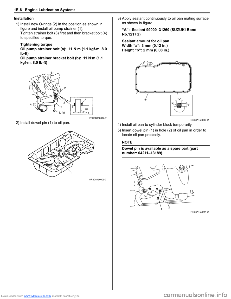
Installation1) Install new O-rings (2) in the position as shown in figure and install o il pump strainer (1).
Tighten strainer bolt (3) first and then bracket bolt (4)
to specified torque.
Tightening torque
Oil pump strainer bolt (a): 11 N·m (1.1 kgf-m, 8.0
lb-ft)
Oil pump strainer bracket bolt (b): 11 N·m (1.1
kgf-m, 8.0 lb-ft)
2) Install dowel pin (1) to oil pan. 3) Apply sealant continuously to oil pan mating surface
as shown in figure.
“A”: Sealant 99000–31260 (SUZUKI Bond
No.1217G)
Sealant amount for oil pan
Width “a”: 3 mm (0.12 in.)
Height “b”: 2 mm (0.08 in.)
4) Install oil pan to cy linder block temporarily.
5) Insert dowel pin (1) in hole (2) of oil pan in order to
locate oil pan precisely.
NOTE
Dowel pin is available as a spare part (part
number: 04211–13189).
I2RH0B150012-01
I4RS0A150005-01
I4RS0A150006-01
21I4RS0A150007-01
Page 359 of 1496

Downloaded from www.Manualslib.com manuals search engine Engine Lubrication System: 1E-7
6) After fitting oil pan to cylinder block, run in securing bolts and start tightening at the center: move wrench
outward, tightening one bolt at a time. Tighten bolts
and nuts to specified torque.
Tightening torque
Oil pan bolt (M6) (a): 11 N·m (1.1 kgf-m, 8.0 lb-ft)
Oil pan bolt (M10) (c): 55 N·m (5.5 kgf-m, 40.0 lb-
ft)
Oil pan nut (e): 11 N·m (1.1 kgf-m, 8.0 lb-ft)
7) Install new gasket and drain plug to oil pan. Tighten drain plug to specified torque.
Tightening torque
Oil pan drain plug (b): 35 N·m (3.5 kgf-m, 25.5 lb-
ft)
8) Tighten transaxle stiffener bolts to specified torque. Tightening torque
Transaxle stiffener bolt (d): 55 N·m (5.5 kgf-m,
40.0 lb-ft)
9) Install exhaust manifold stiffener (2) and exhaust No.1 pipe (1) and heated oxygen sensor No.2
(connector color: green) (3) referring to “Exhaust
System Components in Section 1K”. 10) Install clutch housing lower plate (1).
11) Install oil level gauge.
12) Refill engine with engine oil referring to “Engine Oil
and Filter Change in Section 0B”.
13) Verify that there is no en gine oil leakage and exhaust
gas leakage at each connection.
Oil Pan and Oil Pump Strainer CleaningS7RS0B1506006
• Clean sealing surface between oil pan and cylinder block.
Remove oil, old sealant, and dust from sealing
surface.
• Clean oil pump strainer screen (1).(a)
(b)
(c)(e)
(d)I4RS0A150008-01
2
1
3
I4RS0A150003-01
1I4RS0A150004-01
I2RH0B150016-01
Page 374 of 1496

Downloaded from www.Manualslib.com manuals search engine 1F-11 Engine Cooling System:
Water Pump Removal and InstallationS7RS0B1606014
Removal1) Disconnect negative cable at battery.
2) Drain coolant.
3) Remove water pump / generator drive belt referring to “Water Pump / Generator Drive Belt Removal and
Installation in Section 1J”.
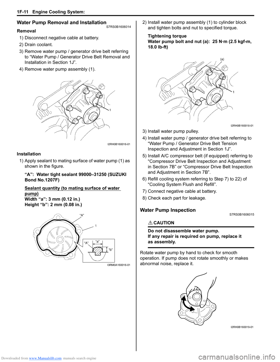
4) Remove water pump assembly (1).
Installation 1) Apply sealant to mating surface of water pump (1) as shown in the figure.
“A”: Water tight sealant 99000–31250 (SUZUKI
Bond No.1207F)
Sealant quantity (to mating surface of water
pump)
Width “a”: 3 mm (0.12 in.)
Height “b”: 2 mm (0.08 in.) 2) Install water pump assemb
ly (1) to cylinder block
and tighten bolts and nut to specified torque.
Tightening torque
Water pump bolt and nut (a): 25 N·m (2.5 kgf-m,
18.0 lb-ft)
3) Install water pump pulley.
4) Install water pump / generator drive belt referring to “Water Pump / Generator Drive Belt Tension
Inspection and Adjustment in Section 1J”.
5) Install A/C compressor belt (if equipped) referring to “Compressor Drive Belt Inspection and Adjustment
in Section 7B” or “Compressor Drive Belt Inspection
and Adjustment in Section 7B”.
6) Refill cooling system referri ng to Step 7) to 22) of
“Cooling System Flush and Refill”.
7) Connect negative cable at battery.
8) Check each part for leakage.
Water Pump InspectionS7RS0B1606015
CAUTION!
Do not disassemble water pump.
If any repair is requir ed on pump, replace it
as assembly.
Rotate water pump by hand to check for smooth
operation. If pump does not rotate smoothly or makes
abnormal noise, replace it.
I2RH0B160016-01
I3RM0A160016-01
I2RH0B160018-01
I2RH0B160019-01
Page 382 of 1496

Downloaded from www.Manualslib.com manuals search engine 1G-7 Fuel System:
Fuel Pressure Relief ProcedureS7RS0B1706003
CAUTION!
This work must not be done when engine is
hot. If done so, it may cause adverse effect to
catalyst.
NOTE
If ECM detects DTC(s) after servicing, clear
DTC(s) referring to “DTC Clearance in
Section 1A”.
1) Make sure that engine is cold.
2) Shift transaxle gear shift lever in “Neutral” (shift select lever in “P” range for A/T model), set parking
brake and block drive wheels.
3) Remove relay / fuse box cover.
4) Disconnect fuel pump relay (1) from relay / fuse box (2).
5) Remove fuel filter cap in order to release fuel vapor pressure in fuel tank, and then reinstall it.
6) Start engine and run it until engine stops for lack of fuel. Repeat cranking engine 2 – 3 times for about 3
seconds each time in order to dissipate fuel pressure
in lines. Fuel connections are now safe for servicing.
7) After servicing, connect fuel pump relay (1) to relay / fuse box and install re lay / fuse box cover.
Fuel Leakage Check ProcedureS7RS0B1706004
After performing any service on fuel system, check to
make sure that there are no fuel leakages as follows.
1) Turn ON ignition switch for 3 seconds (to operate fuel pump) and then turn it OFF.
Repeat this (ON and OFF) 3 or 4 times and apply
fuel pressure to fuel line until fuel pressure is felt by
hand placed on fuel feed hose.
2) In this state, check to see that there are no fuel leakages from any part of fuel system.
Fuel Lines On-Vehicle InspectionS7RS0B1706005
CAUTION!
Due to the fact that fuel feed line (1) is under
high pressure, use special care when
servicing it.
Visually inspect fuel lines for evidence of fuel leakage,
hose crack and deterioration or damage.
Make sure all cl amps are secure.
Replace parts as needed.
Fuel Pipe Removal and InstallationS7RS0B1706006
WARNING!
Before starting the following procedure, be
sure to observe “Precautions on Fuel System
Service” in order to reduce the risk or fire
and personal injury.
Removal
1) Relieve fuel pressure in fuel feed line according to “Fuel Pressure Relief Procedure”.
2) Disconnect negative cable at battery.
3) Disconnect fuel pipe joint and fuel hose (3) from fuel pipe (2) at the front and rear of each fuel pipe
referring to “Fuel Hose Disconnecting and
Reconnecting”.
4) Mark the location of clamps (1) on fuel pipes (2), so that the clamps can be reinstalled to where they
were.
5) Remove pipes (2) with clamp (1) from vehicle.
6) Remove clamp (1) from pipes (2).
1
I4RS0A170004-01
1
I4RS0A170005-01
2
13
I4RS0A170020-01
Page 394 of 1496

Downloaded from www.Manualslib.com manuals search engine 1H-2 Ignition System:
Schematic and Routing Diagram
Ignition System Wiring Circuit DiagramS7RS0B1802001
E23-60
E23-29 12V 5V
5V
E23-1
E23-16
BLK/WHT
BLK/RED
BLK/RED BLK/RED
BLK/YELBLK/YEL
BLK/YEL
GRN
BLKWHT
WHT
BRN/WHT
BLK/ORN
BLK
BLK
C37-20
BLK/RED
PNK
5V
C37-21
BLK/WHT
7
3 4
1
12 5
6
2
11
8
9
10
GRN/YEL
GRN/WHT
C37-6
C37-5 5V
5V
RED/YEL
C37-58
C37-15
C37-30
E23
C37
34
1819
567
1011
17
20
47 46
495051
2122
52 16
25 9
24
14
29
55
57 54 53
59
60 58 2
262728
15
30
56 4832 31
34353637
40
42 39 38
44
45 43 41 331
1213
238
34
1819
567
1011
17
20
47 46
495051
2122
52 16
25 9
24
14
29
55
57 54 53
59
60 58 2
262728
15
30
56 4832 31
34353637
40
42 39 38
44
45 43 41 331
1213
238
13
14
15
16
17
50A50A80A
BLK/ORN
E23-31 BLK
I4RS0B180001-01
1. Ignition switch 7. No.1 spark plug 13. Individual circuit fuse box
No.1
2. Main relay 8. No.2 spark plug 14. “IG ACC” fuse
3. Ignition coil assembly for No.1 and No.4 spark plugs 9. No.3 spark plug 15. “FI” fuse
4. Ignition coil assembly for No.2 and No.3 spark plugs 10. No.4 spark plug 16. Junction block assembly
5. CMP sensor 11. Sensed information (MAP sensor, ECT sensor, MAF and IAT
sensor, TP sensor, Knock sensor, VSS, Electric load signal,
Engine start signal) 17. “IG COIL” fuse
6. CKP sensor 12. Battery fuse box
Page 395 of 1496

Downloaded from www.Manualslib.com manuals search engine Ignition System: 1H-3
Component Location
Ignition System Components LocationS7RS0B1803001
NOTE
The figure shows left-hand steering vehicle. For right-hand steering vehicle, parts with (*) are installed
at the opposite side.
16*
1
2
14
7
5 12 11
410
6
89
3 13*
15
17
I6RS0C180001-01
1. ECM 7. ECT sensor13. Data link connector
2. Ignition coil assembly for No.1 and No.4 spark plugs 8. MAF and IAT sensor 14. Battery fuse box
3. Ignition coil assembly for No.2 and No.3 spark plugs 9. Electric throttle body 15. Relay box
4. CMP sensor 10. Wheel speed sensor (VSS) 16. Junction block assembly
5. CKP sensor 11. High-tension cords
6. MAP sensor 12. Knock sensor
Page 408 of 1496

Downloaded from www.Manualslib.com manuals search engine 1I-7 Starting System:
Spring
Inspect brush springs for wear, damage or other
abnormal conditions. Replace if necessary.
Brush spring tension
Standard: 2.2 kg (4.85 lb)
Limit: 0.6 kg (1.33 lb)
Brush Holder
• Check movement of brush in brush holder. If brush movement within brush holder is sluggish, check
brush holder for distortion and sliding faces for
contamination.
Clean or correct as necessary.
• Check for continuity across insulated brush (positive side) and grounded brush (negative side).
If continuity exists, brus h holder is grounded due to
defective insulation and should be replaced.
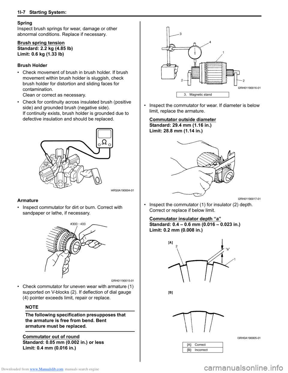
Armature
• Inspect commutator for dirt or burn. Correct with sandpaper or lathe, if necessary.
• Check commutator for uneven wear with armature (1) supported on V-blocks (2). If deflection of dial gauge
(4) pointer exceeds limit, repair or replace.
NOTE
The following specification presupposes that
the armature is free from bend. Bent
armature must be replaced.
Commutator out of round
Standard: 0.05 mm (0.002 in.) or less
Limit: 0.4 mm (0.016 in.) • Inspect the commutator for wear. If diameter is below
limit, replace the armature.
Commutator outside diameter
Standard: 29.4 mm (1.16 in.)
Limit: 28.8 mm (1.14 in.)
• Inspect the commutator (1) for insulator (2) depth. Correct or replace if below limit.
Commutator insulator depth “a”
Standard: 0.4 – 0.6 mm (0.016 – 0.023 in.)
Limit: 0.2 mm (0.008 in.)
I4RS0A190004-01
I2RH01190015-01
3. Magnetic stand
[A]: Correct
[B]: Incorrect
I2RH01190016-01
I2RH01190017-01
I3RH0A190005-01