2006 SUZUKI SWIFT drive axle
[x] Cancel search: drive axlePage 662 of 1496

Downloaded from www.Manualslib.com manuals search engine 5A-18 Automatic Transmission/Transaxle:
Visual InspectionS7RS0B5104002
Visually check the following parts and systems.
Malfunction Indicator Lamp (MIL) CheckS7RS0B5104003
Refer to the same item in “Malfunction Indicator Lam p (MIL) Check in Section 1A” for checking procedure.
Transmission Warning Light CheckS7RS0B5104004
1) Turn ignition switch ON.
2) Check that transmission warning light lights for about 2 – 4 sec. and then goes OFF.
If anything faulty is found, advance “Transmission Warn ing Light Circuit Check – Light Does Not Come “ON” at
Ignition Switch ON” or “Transmission Warning Light Circu it Check – Light Remains “ON” at Ignition Switch ON”.
Inspection item Referring
• A/T fluid ----- level, leakage, color “Automatic Transaxle Fluid Level Inspection in Section 0B”
• A/T fluid hoses ----- disconnection, looseness, deterioration “A/T Fluid Cooler Hoses Replacement”
• A/T select cable ----- installation “S elect Cable Removal and Installation”
• Engine oil ----- level, leakage “Engine Oil and Filter Change in Section 0B”
• Engine coolant ----- level, leakage “Engine Coolant Change in Section 0B”
• Engine mountings ----- play, looseness, damage “Engine Assembly Removal and Installation in Section 1D”
• Suspension ----- play, looseness “Suspension, Wheels and Tires Symptom Diagnosis in Section 2A”
• Drive shafts ----- damage “Front Drive Shaft Assembly On-Vehicle Inspection in Section 3A”
• Battery ----- indicator condition, corrosion of terminal “Battery Inspection in Section 1J”
• Connectors of electric wire harness ----- disconnection, friction “Electronic Shift Control System Components
Location”
• Fuses ----- burning
• Parts ----- installation, damage
• Bolts ----- looseness
• Other parts that can be checked visually
Also check the following items at engine start, if possible.
• Transmission warning light (if equipped) ----- Operation “Transmission Warning Light Check”
• Malfunction indicator lamp ----- Operation “Malfunction Indicator Lamp (MIL) Check”
• Charge warning lamp ----- Operation “Generator Symptom Diagnosis in Section 1J”
• Engine oil pressure warning lamp ----- Operation “Oil Pressure Warning Ligh t Symptom Diagnosis in
Section 9C”
• Engine coolant temp. meter ----- Operation “Engine Coolant Temperature (ECT) Meter
Symptom Diagnosis in Section 9C”
• Other parts that can be checked visually
I4RS0A510008-01
Page 665 of 1496
Downloaded from www.Manualslib.com manuals search engine Automatic Transmission/Transaxle: 5A-21
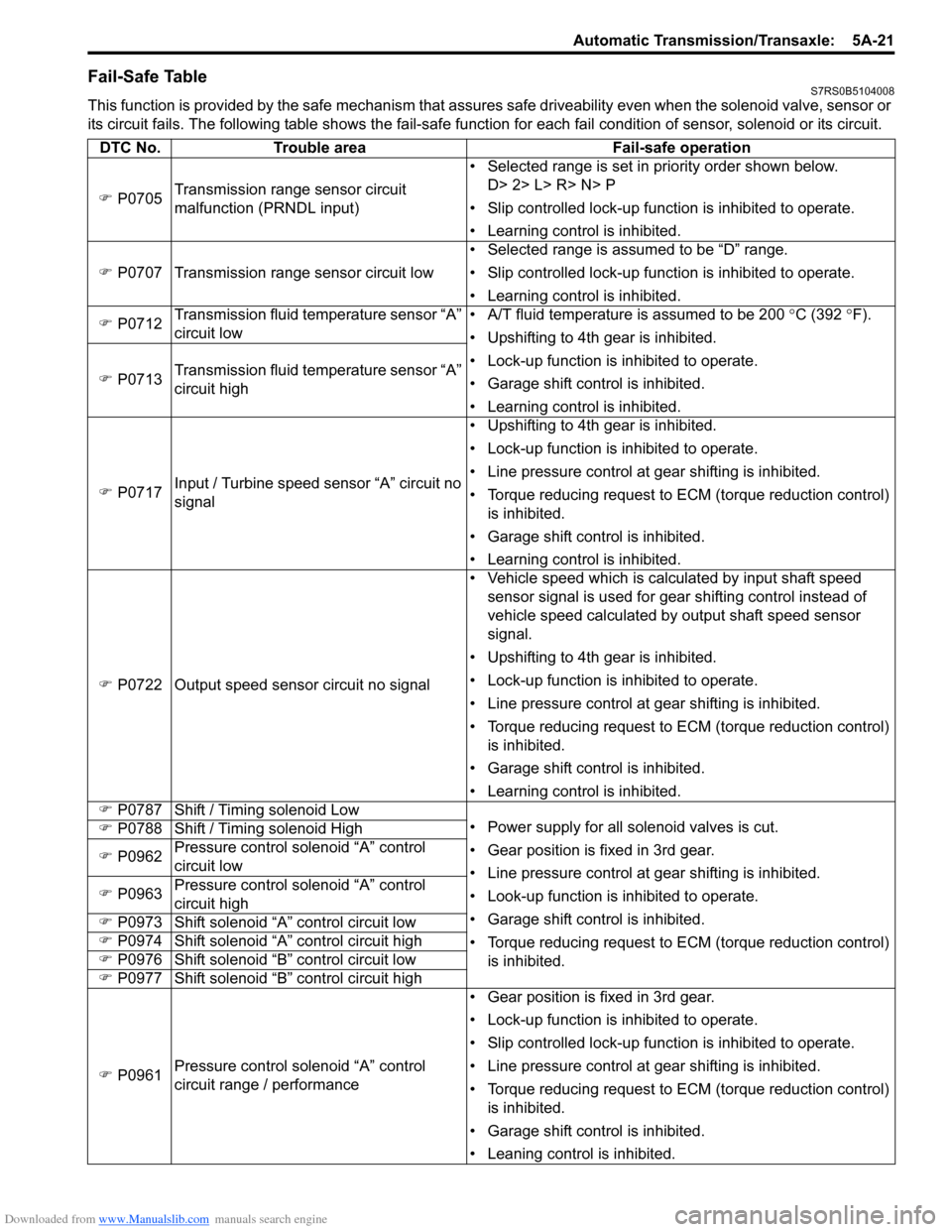
Fail-Safe TableS7RS0B5104008
This function is provided by the safe mechanism that assures safe driveability even when the solenoid valve, sensor or
its circuit fails. The following table shows th e fail-safe function for each fail condition of sensor, solenoid or its circuit.
DTC No. Trouble area Fail-safe operation
�) P0705 Transmission range sensor circuit
malfunction (PRNDL input) • Selected range is set in priority order shown below.
D> 2> L> R> N> P
• Slip controlled lock-up function is inhibited to operate.
• Learning control is inhibited.
�) P0707 Transmission range sensor circuit low • Selected range is assumed to be “D” range.
• Slip controlled lock-up function is inhibited to operate.
• Learning control is inhibited.
�) P0712 Transmission fluid temperature sensor “A”
circuit low • A/T fluid temperature is assumed to be 200
°C (392 °F).
• Upshifting to 4th gear is inhibited.
• Lock-up function is inhibited to operate.
• Garage shift control is inhibited.
• Learning control is inhibited.
�)
P0713 Transmission fluid temperature sensor “A”
circuit high
�) P0717 Input / Turbine speed sensor “A” circuit no
signal • Upshifting to 4th gear is inhibited.
• Lock-up function is inhibited to operate.
• Line pressure control at gear shifting is inhibited.
• Torque reducing request to ECM (torque reduction control)
is inhibited.
• Garage shift control is inhibited.
• Learning control is inhibited.
�) P0722 Output speed sensor circuit no signal • Vehicle speed which is calculated by input shaft speed
sensor signal is used for gear shifting control instead of
vehicle speed calculated by output shaft speed sensor
signal.
• Upshifting to 4th gear is inhibited.
• Lock-up function is inhibited to operate.
• Line pressure control at gear shifting is inhibited.
• Torque reducing request to ECM (torque reduction control) is inhibited.
• Garage shift control is inhibited.
• Learning control is inhibited.
�) P0787 Shift / Timing solenoid Low
• Power supply for all solenoid valves is cut.
• Gear position is fixed in 3rd gear.
• Line pressure control at gear shifting is inhibited.
• Look-up function is inhibited to operate.
• Garage shift control is inhibited.
• Torque reducing request to ECM (torque reduction control)
is inhibited.
�)
P0788 Shift / Timing solenoid High
�) P0962 Pressure control solenoid “A” control
circuit low
�) P0963 Pressure control solenoid “A” control
circuit high
�) P0973 Shift solenoid “A” control circuit low
�) P0974 Shift solenoid “A” control circuit high
�) P0976 Shift solenoid “B” control circuit low
�) P0977 Shift solenoid “B” control circuit high
�) P0961 Pressure control solenoid “A” control
circuit range / performance • Gear position is fixed in 3rd gear.
• Lock-up function is inhibited to operate.
• Slip controlled lock-up function is inhibited to operate.
• Line pressure control at gear shifting is inhibited.
• Torque reducing request to ECM (torque reduction control)
is inhibited.
• Garage shift control is inhibited.
• Leaning control is inhibited.
Page 666 of 1496
Downloaded from www.Manualslib.com manuals search engine 5A-22 Automatic Transmission/Transaxle:
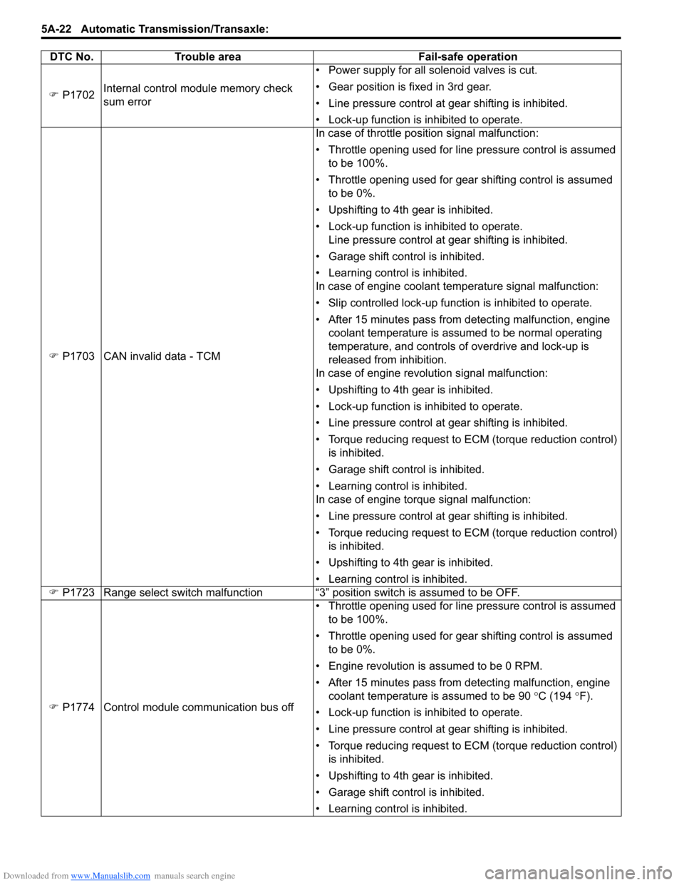
�) P1702 Internal control module memory check
sum error • Power supply for all solenoid valves is cut.
• Gear position is fixed in 3rd gear.
• Line pressure control at gear shifting is inhibited.
• Lock-up function is inhibited to operate.
�) P1703 CAN invalid data - TCM In case of throttle position signal malfunction:
• Throttle opening used for line pressure control is assumed
to be 100%.
• Throttle opening used for gear shifting control is assumed to be 0%.
• Upshifting to 4th gear is inhibited.
• Lock-up function is inhibited to operate. Line pressure control at gear shifting is inhibited.
• Garage shift control is inhibited.
• Learning control is inhibited.
In case of engine coolant temperature signal malfunction:
• Slip controlled lock-up function is inhibited to operate.
• After 15 minutes pass from detecting malfunction, engine coolant temperature is assumed to be normal operating
temperature, and controls of overdrive and lock-up is
released from inhibition.
In case of engine revolution signal malfunction:
• Upshifting to 4th gear is inhibited.
• Lock-up function is inhibited to operate.
• Line pressure control at gear shifting is inhibited.
• Torque reducing request to ECM (torque reduction control) is inhibited.
• Garage shift control is inhibited.
• Learning control is inhibited.
In case of engine torque signal malfunction:
• Line pressure control at gear shifting is inhibited.
• Torque reducing request to ECM (torque reduction control) is inhibited.
• Upshifting to 4th gear is inhibited.
• Learning control is inhibited.
�) P1723 Range select switch malfunction “3” position switch is assumed to be OFF.
�) P1774 Control module communication bus off • Throttle opening used for line pressure control is assumed
to be 100%.
• Throttle opening used for gear shifting control is assumed to be 0%.
• Engine revolution is assumed to be 0 RPM.
• After 15 minutes pass from detecting malfunction, engine coolant temperature is assumed to be 90 °C (194 °F).
• Lock-up function is inhibited to operate.
• Line pressure control at gear shifting is inhibited.
• Torque reducing request to ECM (torque reduction control) is inhibited.
• Upshifting to 4th gear is inhibited.
• Garage shift control is inhibited.
• Learning control is inhibited.
DTC No. Trouble area Fail-safe operation
Page 671 of 1496
Downloaded from www.Manualslib.com manuals search engine Automatic Transmission/Transaxle: 5A-27
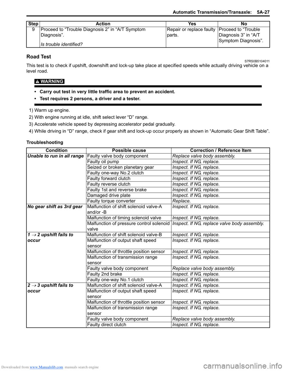
Road TestS7RS0B5104011
This test is to check if upshift, downshift and lock-up take place at specified speeds while actually driving vehicle on a
level road.
WARNING!
• Carry out test in very little traffic area to prevent an accident.
• Test requires 2 persons, a driver and a tester.
1) Warm up engine.
2) With engine running at idle, shift select lever “D” range.
3) Accelerate vehicle speed by depressing accelerator pedal gradually.
4) While driving in “D” range, check if gear shift and lock-up occur properly as shown in “Automatic Gear Shift Table”.
Troubleshooting 9 Proceed to “Trouble Diag
nosis 2” in “A/T Symptom
Diagnosis”.
Is trouble identified? Repair or replace faulty
parts.
Proceed to “Trouble
Diagnosis 3” in “A/T
Symptom Diagnosis”.
Step Action Yes No
Condition
Possible cause Correction / Reference Item
Unable to run in all range Faulty valve body component Replace valve body assembly.
Faulty oil pump Inspect. If NG, replace.
Seized or broken planetary gear Inspect. If NG, replace.
Faulty one-way No.2 clutch Inspect. If NG, replace.
Faulty forward clutch Inspect. If NG, replace.
Faulty reverse clutch Inspect. If NG, replace.
Faulty 1st and reverse brake Inspect. If NG, replace.
Damaged drive plate Inspect. If NG, replace.
Faulty torque converter Replace.
No gear shift as 3rd gear Malfunction of shift solenoid valve-A
and/or -B Inspect. If NG, replace.
Malfunction of timing solenoid valve Inspect. If NG, replace.
Malfunction of pressure control solenoid
valve Inspect. If NG, replace valve body assembly.
1
→ 2 upshift fails to
occur Malfunction of shif
t solenoid valve-B Inspect. If NG, replace.
Malfunction of output shaft speed
sensor Inspect. If NG, replace.
Malfunction of throttle position sensor Inspect. If NG, replace.
Malfunction of transmission range
sensor Inspect. If NG, replace.
Faulty valve body component Replace valve body assembly.
Faulty 2nd brake Inspect. If NG, replace.
Faulty one-way No.1 clutch Inspect. If NG, replace.
2
→ 3 upshift fails to
occur Malfunction of shif
t solenoid valve-A Inspect. If NG, replace.
Malfunction of output shaft speed
sensor Inspect. If NG, replace.
Malfunction of throttle position sensor Inspect. If NG, replace.
Malfunction of transmission range
sensor Inspect. If NG, replace.
Faulty valve body component Replace valve body assembly.
Faulty direct clutch Inspect. If NG, replace.
Page 673 of 1496
Downloaded from www.Manualslib.com manuals search engine Automatic Transmission/Transaxle: 5A-29
Manual Road TestS7RS0B5104012
WARNING!
Carry out test in very little traffic area to prevent an accident.
Test requires 2 persons, a driver and a tester.
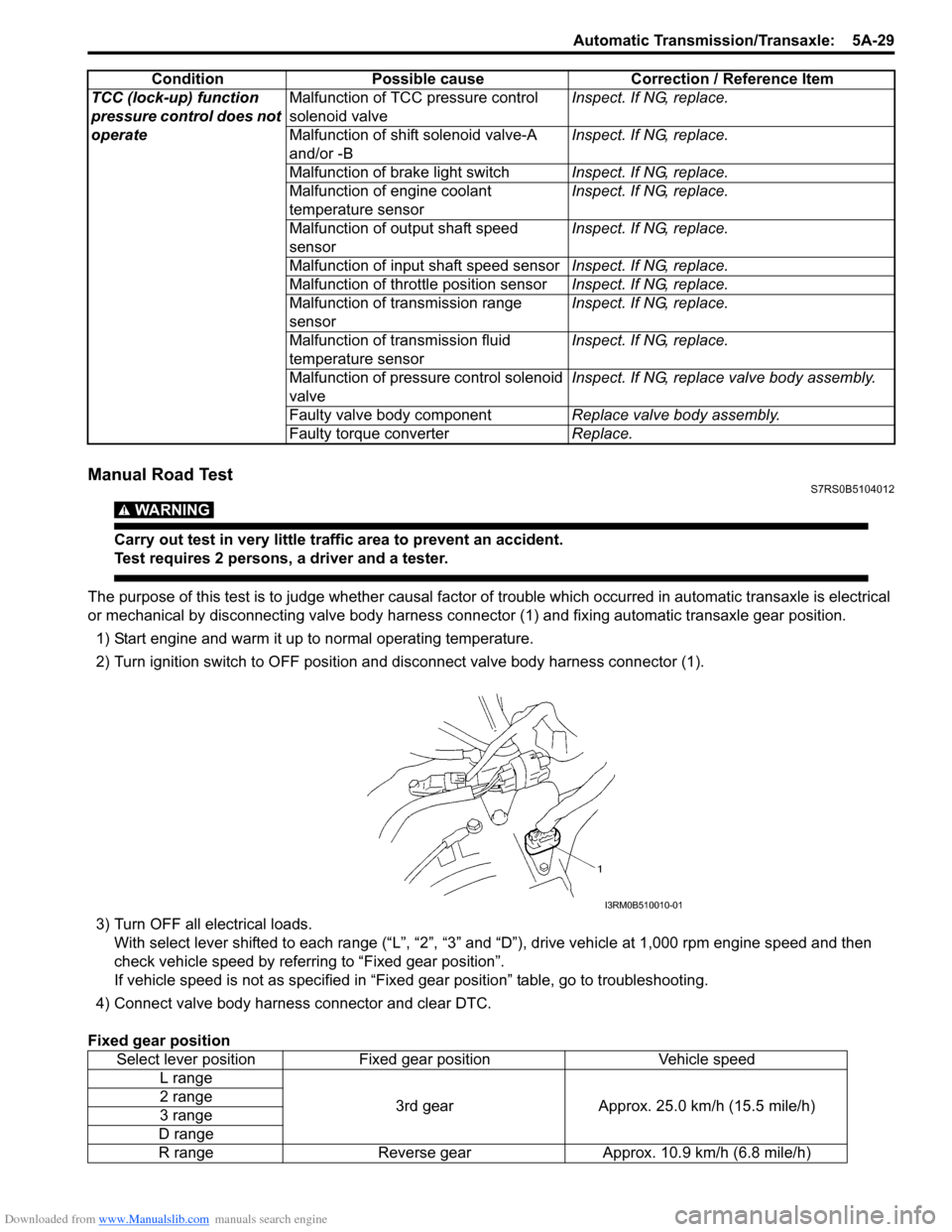
The purpose of this test is to judge whether causal factor of trouble which occurred in automatic transaxle is electrical
or mechanical by disconnecting valve body harness co nnector (1) and fixing automatic transaxle gear position.
1) Start engine and warm it up to normal operating temperature.
2) Turn ignition switch to OFF position and disconnect valve body harness connector (1).
3) Turn OFF all electrical loads. With select lever shifted to each ra nge (“L”, “2”, “3” and “D”), drive vehi cle at 1,000 rpm engine speed and then
check vehicle speed by referring to “Fixed gear position”.
If vehicle speed is not as specified in “Fix ed gear position” table, go to troubleshooting.
4) Connect valve body harness connector and clear DTC.
Fixed gear position TCC (lock-up) function
pressure control does not
operate
Malfunction of TCC pressure control
solenoid valve
Inspect. If NG, replace.
Malfunction of shif t solenoid valve-A
and/or -B Inspect. If NG, replace.
Malfunction of brake light switch Inspect. If NG, replace.
Malfunction of engine coolant
temperature sensor Inspect. If NG, replace.
Malfunction of output shaft speed
sensor Inspect. If NG, replace.
Malfunction of input shaft speed sensor Inspect. If NG, replace.
Malfunction of throttle position sensor Inspect. If NG, replace.
Malfunction of transmission range
sensor Inspect. If NG, replace.
Malfunction of transmission fluid
temperature sensor Inspect. If NG, replace.
Malfunction of pressure control solenoid
valve Inspect. If NG, replace valve body assembly.
Faulty valve body component Replace valve body assembly.
Faulty torque converter Replace.
Condition
Possible cause Correction / Reference Item
Select lever positionFixed gear position Vehicle speed
L range
3rd gearApprox. 25.0 km/h (15.5 mile/h)
2 range
3 range
D range
R range Reverse gear Approx. 10.9 km/h (6.8 mile/h)
I3RM0B510010-01
Page 684 of 1496
Downloaded from www.Manualslib.com manuals search engine 5A-40 Automatic Transmission/Transaxle:
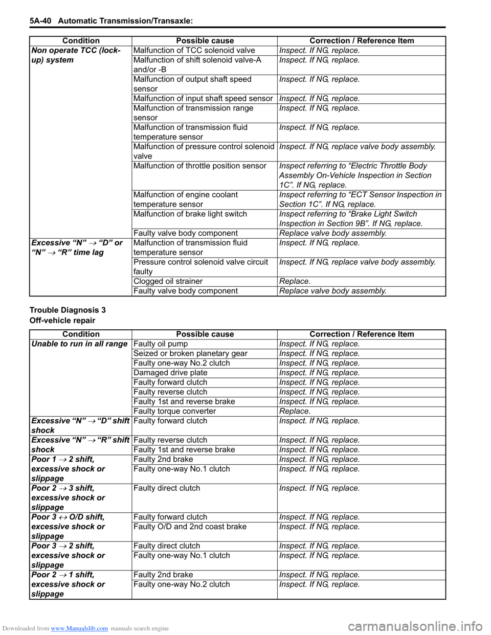
Trouble Diagnosis 3
Off-vehicle repairNon operate TCC (lock-
up) system
Malfunction of TCC solenoid valve
Inspect. If NG, replace.
Malfunction of shift solenoid valve-A
and/or -B Inspect. If NG, replace.
Malfunction of output shaft speed
sensor Inspect. If NG, replace.
Malfunction of input shaft speed sensor Inspect. If NG, replace.
Malfunction of transmission range
sensor Inspect. If NG, replace.
Malfunction of transmission fluid
temperature sensor Inspect. If NG, replace.
Malfunction of pressure control solenoid
valve Inspect. If NG, replace valve body assembly.
Malfunction of throttle position sensor Inspect referring to “Electric Throttle Body
Assembly On-Vehicle Inspection in Section
1C”. If NG, replace.
Malfunction of engine coolant
temperature sensor Inspect referring to “ECT Sensor Inspection in
Section 1C”. If NG, replace.
Malfunction of brake light switch Inspect referring to “Brake Light Switch
Inspection in Section 9B”. If NG, replace.
Faulty valve body component Replace valve body assembly.
Excessive “N”
→ “D” or
“N”
→ “R” time lag Malfunction of transmission fluid
temperature sensor Inspect. If NG, replace.
Pressure control solenoid valve circuit
faulty Inspect. If NG, replace valve body assembly.
Clogged oil strainer Replace.
Faulty valve body component Replace valve body assembly.
Condition Possible cause Correction / Reference Item
Condition
Possible cause Correction / Reference Item
Unable to run in all range Faulty oil pump Inspect. If NG, replace.
Seized or broken planetary gear Inspect. If NG, replace.
Faulty one-way No.2 clutch Inspect. If NG, replace.
Damaged drive plate Inspect. If NG, replace.
Faulty forward clutch Inspect. If NG, replace.
Faulty reverse clutch Inspect. If NG, replace.
Faulty 1st and reverse brake Inspect. If NG, replace.
Faulty torque converter Replace.
Excessive “N”
→ “D” shift
shock Faulty forward clutch
Inspect. If NG, replace.
Excessive “N”
→ “R” shift
shock Faulty reverse clutch
Inspect. If NG, replace.
Faulty 1st and reverse brake Inspect. If NG, replace.
Poor 1
→ 2 shift,
excessive shock or
slippage Faulty 2nd brake
Inspect. If NG, replace.
Faulty one-way No.1 clutch Inspect. If NG, replace.
Poor 2
→ 3 shift,
excessive shock or
slippage Faulty direct clutch
Inspect. If NG, replace.
Poor 3
↔ O/D shift,
excessive shock or
slippage Faulty forward clutch
Inspect. If NG, replace.
Faulty O/D and 2nd coast brake Inspect. If NG, replace.
Poor 3
→ 2 shift,
excessive shock or
slippage Faulty direct clutch
Inspect. If NG, replace.
Faulty one-way No.1 clutch Inspect. If NG, replace.
Poor 2
→ 1 shift,
excessive shock or
slippage Faulty 2nd brake
Inspect. If NG, replace.
Faulty one-way No.2 clutch Inspect. If NG, replace.
Page 685 of 1496
Downloaded from www.Manualslib.com manuals search engine Automatic Transmission/Transaxle: 5A-41
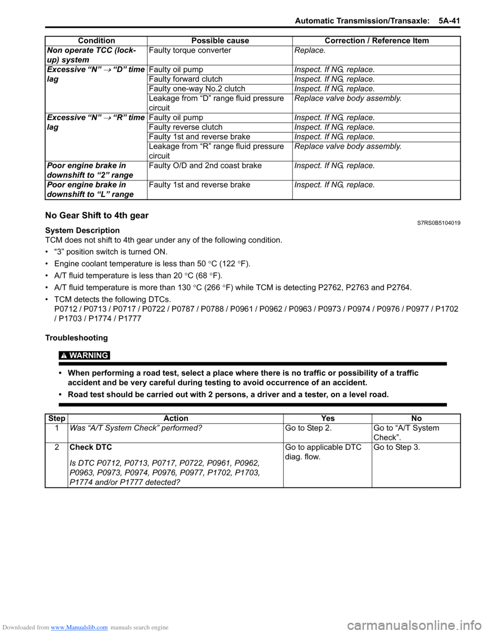
No Gear Shift to 4th gearS7RS0B5104019
System Description
TCM does not shift to 4th gear under any of the following condition.
• “3” position switch is turned ON.
• Engine coolant temperature is less than 50 °C (122 °F).
• A/T fluid temperature is less than 20 °C (68 °F).
• A/T fluid temperature is more than 130 °C (266 °F) while TCM is detecting P2762, P2763 and P2764.
• TCM detects the following DTCs. P0712 / P0713 / P0717 / P0722 / P0787 / P0788 / P0961 / P0962 / P0963 / P0973 / P0974 / P0976 / P0977 / P1702
/ P1703 / P1774 / P1777
Troubleshooting
WARNING!
• When performing a road test, select a place where there is no traffic or possibility of a traffic accident and be very careful during testing to avoid occurrence of an accident.
• Road test should be carried out with 2 persons, a driver and a tester, on a level road.
Non operate TCC (lock-
up) system Faulty torque converter
Replace.
Excessive “N”
→ “D” time
lag Faulty oil pump
Inspect. If NG, replace.
Faulty forward clutch Inspect. If NG, replace.
Faulty one-way No.2 clutch Inspect. If NG, replace.
Leakage from “D” range fluid pressure
circuit Replace valve body assembly.
Excessive “N”
→ “R” time
lag Faulty oil pump
Inspect. If NG, replace.
Faulty reverse clutch Inspect. If NG, replace.
Faulty 1st and reverse brake Inspect. If NG, replace.
Leakage from “R” range fluid pressure
circuit Replace valve body assembly.
Poor engine brake in
downshift to “2” range Faulty O/D and 2nd coast brake
Inspect. If NG, replace.
Poor engine brake in
downshift to “L” range Faulty 1st and reverse brake
Inspect. If NG, replace.
Condition Possible cause Correction / Reference Item
Step
Action YesNo
1 Was “A/T System Check” performed? Go to Step 2.Go to “A/T System
Check”.
2 Check DTC
Is DTC P0712, P0713, P0717, P0722, P0961, P0962,
P0963, P0973, P0974, P0976, P0977, P1702, P1703,
P1774 and/or P1777 detected? Go to applicable DTC
diag. flow.
Go to Step 3.
Page 686 of 1496
Downloaded from www.Manualslib.com manuals search engine 5A-42 Automatic Transmission/Transaxle:
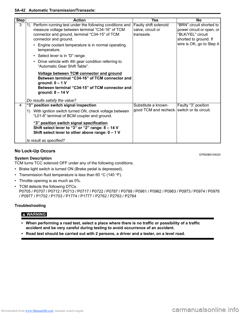
No Lock-Up OccursS7RS0B5104020
System Description
TCM turns TCC solenoid OFF under any of the following conditions.
• Brake light switch is turned ON (Brake pedal is depressed).
• Transmission fluid temperat ure is less than 60 °C (140 °F).
• Throttle opening is as much as 0%.
• TCM detects the following DTCs. P0705 / P0707 / P0712 / P0713 / P0717 / P0722 / P0787 / P0788 / P0961 / P0962 / P0963 / P0973 / P0974 / P0976
/ P0977 / P1702 / P1703 / P1774 / P1777 / P2762 / P2763 / P2764
Troubleshooting
WARNING!
• When performing a road test, select a place where there is no traffic or possibility of a traffic accident and be very careful during testing to avoid occurrence of an accident.
• Road test should be carried out with 2 persons, a driver and a tester, on a level road.
3 1) Perform running test under the following conditions and measure voltage between terminal “C34-16” of TCM
connector and ground, terminal “C34-15” of TCM
connector and ground.
• Engine coolant temperature is in normal operating temperature.
• Select lever is in “D” range.
• Drive vehicle with 4th gear condition referring to “Automatic Gear Shift Table”.
Voltage between TCM connector and ground
Between terminal “C34-16” of TCM connector and
ground: 0 – 1 V
Between terminal “C34-15” of TCM connector and
ground: 8 – 14 V
Do results satisfy the value? Faulty shift solenoid
valve, circuit or
transaxle.
“BRN” circuit shorted to
power circuit or open, or
“BLK/YEL” circuit
shorted to ground. If
wire is OK, go to Step 4.
4 “3” position switch signal inspection
1) With ignition switch turned ON, check voltage between
“L01-8” terminal of BCM coupler and ground.
“3” position switch signal specification
Shift select lever to “3” or “2” range: 8 – 14 V
Shift select lever to other above range: 0 – 1 V
Is result as specified? Substitute a known-
good TCM and recheck.
Faulty “3” position
switch or its circuit.
Step Action Yes No