2006 SUZUKI SWIFT throttle actuator
[x] Cancel search: throttle actuatorPage 275 of 1496
Downloaded from www.Manualslib.com manuals search engine Engine Electrical Devices: 1C-3
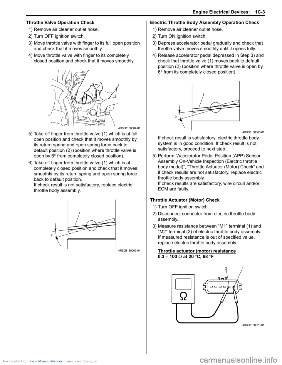
Throttle Valve Operation Check1) Remove air cleaner outlet hose.
2) Turn OFF ignition switch.
3) Move throttle valve with finger to its full open position and check that it moves smoothly.
4) Move throttle valve with fi nger to its completely
closed position and check that it moves smoothly.
5) Take off finger from throttle valve (1) which is at full open position and check that it moves smoothly by
its return spring and open spring force back to
default position (2) (positio n where throttle valve is
open by 6 ° from completely closed position).
6) Take off finger from throttle valve (1) which is at completely closed position and check that it moves
smoothly by its return spring and open spring force
back to default position.
If check result is not satisfactory, replace electric
throttle body assembly. Electric Throttle Body
Assembly Operation Check
1) Remove air cleaner outlet hose.
2) Turn ON ignition switch.
3) Depress accelerator pedal gradually and check that throttle valve moves smoo thly until it opens fully.
4) Release accelerator pedal depressed in Step 3) and check that throttle valve (1) moves back to default
position (2) (position where throttle valve is open by
6° from its completely closed position).
If check result is satisfactory, electric throttle body
system is in good condition. If check result is not
satisfactory, proceed to next step.
5) Perform “Accelerator Pe dal Position (APP) Sensor
Assembly On-Vehicle Inspection (Electric throttle
body model)”, “Throttle Actuator (Motor) Check” and
if check results are not satisfactory, replace electric
throttle body assembly.
If check results are satisfactory, wire circuit and/or
ECM are faulty.
Throttle Actuator (Motor) Check 1) Turn OFF ignition switch.
2) Disconnect connector from electric throttle body assembly.
3) Measure resistance between “M1” terminal (1) and “M2” terminal (2) of electric throttle body assembly.
If measured resistance is out of specified value,
replace electric throttle body assembly.
Throttle actuator (motor) resistance
0.3 – 100 Ω at 20 °C, 68 °F
I4RS0B130004-01
1
2
I4RS0B130005-01
1
2
I4RS0B130005-01
2 1
I4RS0B130023-01
Page 667 of 1496
Downloaded from www.Manualslib.com manuals search engine Automatic Transmission/Transaxle: 5A-23
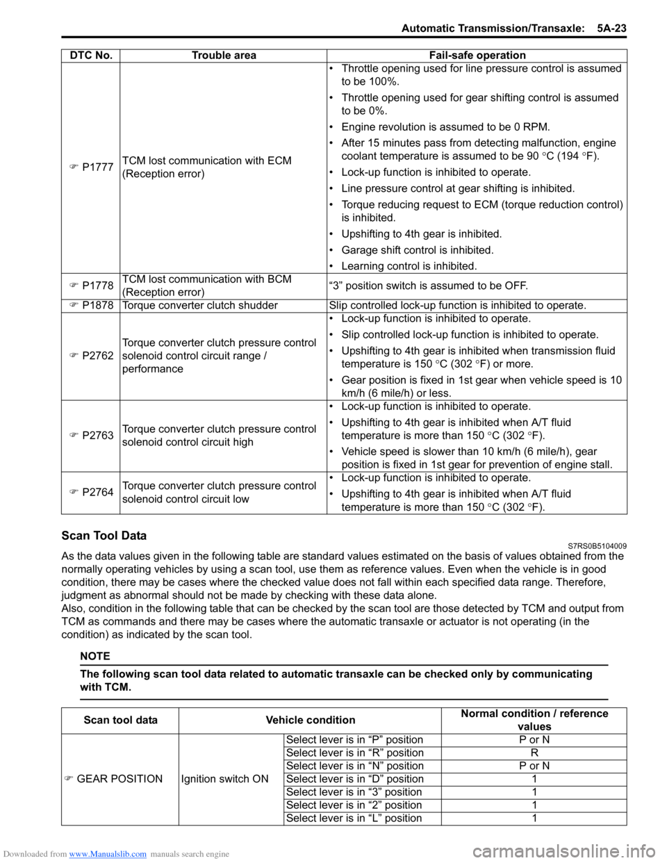
Scan Tool DataS7RS0B5104009
As the data values given in the following table are standard values estimated on the basis of values obtained from the
normally operating vehicles by using a scan tool, use them as reference values. Even when the vehicle is in good
condition, there may be cases where the checked value does not fall within each specified data range. Therefore,
judgment as abnormal should not be made by checking with these data alone.
Also, condition in the following table that can be checked by the scan tool are those detected by TCM and output from
TCM as commands and there may be cases where the auto matic transaxle or actuator is not operating (in the
condition) as indicated by the scan tool.
NOTE
The following scan tool data related to automatic transaxle can be checked only by communicating
with TCM.
�) P1777 TCM lost communication with ECM
(Reception error) • Throttle opening used for line pressure control is assumed
to be 100%.
• Throttle opening used for gear shifting control is assumed to be 0%.
• Engine revolution is assumed to be 0 RPM.
• After 15 minutes pass from detecting malfunction, engine coolant temperature is assumed to be 90 °C (194 °F).
• Lock-up function is inhibited to operate.
• Line pressure control at gear shifting is inhibited.
• Torque reducing request to ECM (torque reduction control) is inhibited.
• Upshifting to 4th gear is inhibited.
• Garage shift control is inhibited.
• Learning control is inhibited.
�) P1778 TCM lost communication with BCM
(Reception error) “3” position switch is assumed to be OFF.
�) P1878 Torque converter clutch shudder Slip contro lled lock-up function is inhibited to operate.
�) P2762 Torque converter clutch pressure control
solenoid control circuit range /
performance • Lock-up function is inhibited to operate.
• Slip controlled lock-up function is inhibited to operate.
• Upshifting to 4th gear is inhibited when transmission fluid
temperature is 150 °C (302 ° F) or more.
• Gear position is fixed in 1st gear when vehicle speed is 10 km/h (6 mile/h) or less.
�) P2763 Torque converter clutch pressure control
solenoid control circuit high • Lock-up function is inhibited to operate.
• Upshifting to 4th gear is inhibited when A/T fluid
temperature is more than 150 °C (302 °F).
• Vehicle speed is slower than 10 km/h (6 mile/h), gear position is fixed in 1st gear for prevention of engine stall.
�) P2764 Torque converter clutch pressure control
solenoid control circuit low • Lock-up function is inhibited to operate.
• Upshifting to 4th gear is inhibited when A/T fluid
temperature is more than 150 °C (302 °F).
DTC No. Trouble area Fail-safe operation
Scan tool data
Vehicle condition Normal condition / reference
values
�) GEAR POSITION Ignition switch ON Select lever is in “P” position
P or N
Select lever is in “R” position R
Select lever is in “N” position P or N
Select lever is in “D” position 1
Select lever is in “3” position 1
Select lever is in “2” position 1
Select lever is in “L” position 1
Page 963 of 1496
Downloaded from www.Manualslib.com manuals search engine Air Conditioning System: Manual Type 7B-15
A/C System Inspection at ECMS7RS0B7214004
Voltage Check
When checking voltage at ECM connector terminals related to A/C system, refer to “DTC P2101: Throttle Actuator
Control Motor Circuit Range / Performance in Section 1A”.
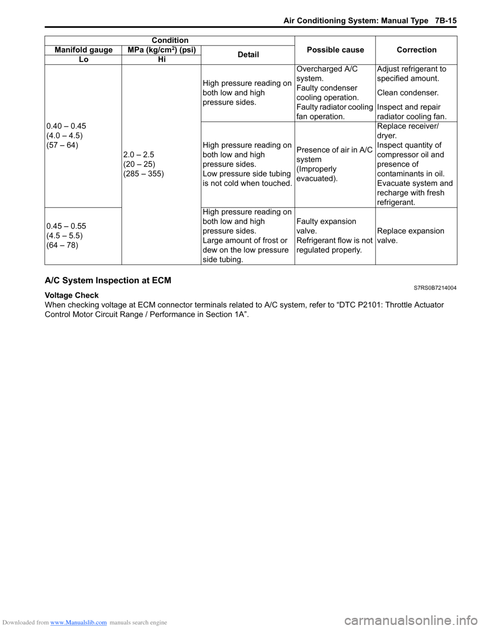
0.40 – 0.45
(4.0 – 4.5)
(57 – 64)
2.0 – 2.5
(20 – 25)
(285 – 355) High pressure reading on
both low and high
pressure sides.
Overcharged A/C
system.
Adjust refrigerant to
specified amount.
Faulty condenser
cooling operation. Clean condenser.
Faulty radiator cooling
fan operation. Inspect and repair
radiator cooling fan.
High pressure reading on
both low and high
pressure sides.
Low pressure side tubing
is not cold when touched. Presence of air in A/C
system
(Improperly
evacuated).Replace receiver/
dryer.
Inspect quantity of
compressor oil and
presence of
contaminants in oil.
Evacuate system and
recharge with fresh
refrigerant.
0.45 – 0.55
(4.5 – 5.5)
(64 – 78) High pressure reading on
both low and high
pressure sides.
Large amount of frost or
dew on the low pressure
side tubing.Faulty expansion
valve.
Refrigerant flow is not
regulated properly.
Replace expansion
valve.
Condition
Possible cause Correction
Manifold gauge MPa (kg/cm
2) (psi)
Detail
Lo Hi
Page 1185 of 1496

Downloaded from www.Manualslib.com manuals search engine Wiring Systems: 9A-14
E: Main harness (RHD)
E: Main harness
56
E06E12
E03or
E85
E07
E09
E08
E13
E10
E11E05 E04
E01 E02
E19
7
22
E34E31
E32
E57
E24
(TO C36)
E33
E36
E35
E30
E29
E28
E20
E21
E22
E27
E26
E23
E25E17E56
E18
E14 E15
E55
E
I7RS0B910902-02
No./Color
Connective position No./ColorConnective position
E01/GRY Windshield wiper motor E22/N Front position light (L)
E02/GRY Brake fluid level switch E23/GRY ECM
E03/BLK ABS control module E24/N Engine Harness (To C36)
E04/BLK A/C pressure sensor E25/BLK Wheel speed sensor (FL)
E05/BLK Wheel speed sensor (FR) E26/N Main fuse box
E06/N Side turn signal light (R) E27/BLK Main fuse box
E07/N Front position light (R) E28/BLK Radiator fan relay #1
E08/BLK Head light (R) E29/BLK Radiator fan relay #2
E09/GRY Front turn signal light (R) E30/BLK Radiator fan relay #3
E10/GRN Rear washer motor E31/BLK Starting motor relay
E11/BLU Windshield washer motor E32/BLK Main relay
E12/BLK (IF EQPD) Front fog light (R)
E33/BLK A/T relay
E13/YEL Forward sensor E34/BLK (IF
EQPD) Front fog light relay
E14/BLK Outside air temperature sensor E35/BLK Fuel pump relay
E15/BLK Horn E36/BLK A/C compressor relay
E17/BLK Radiator fan motor E55/- Weld splice
E18/BLK (IF EQPD) Front fog light (L) E56/BLK
(M16A
engine) Throttle actuator control relay
E19/N Side turn signal light (L) E57/BLK Diagnosis connector #1
E20/GRY Front turn signal light (L) E85/BLK (IF
EQPD) ESP
® control module
E21/BLK Headlight (R)
Page 1205 of 1496
Downloaded from www.Manualslib.com manuals search engine Wiring Systems: 9A-34
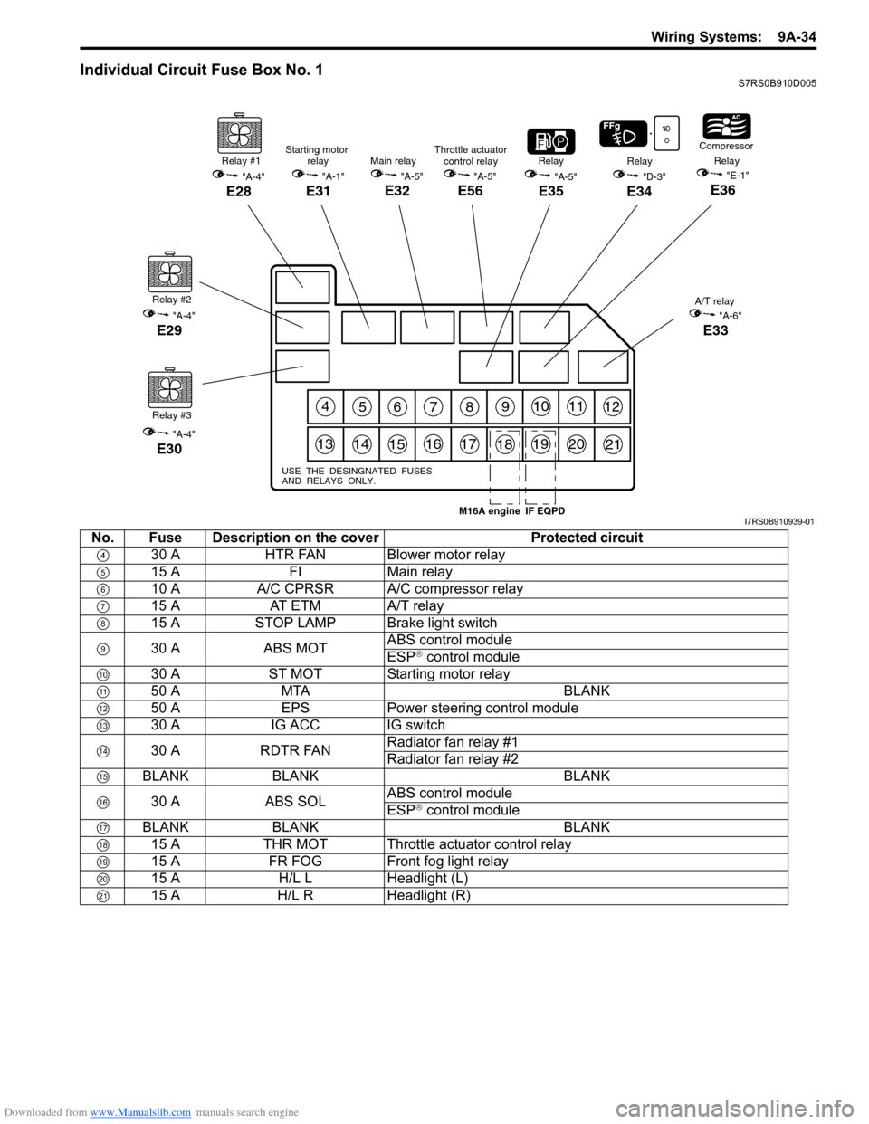
Individual Circuit Fuse Box No. 1S7RS0B910D005
456789101112
131415161718192021
USE THE DESINGNATED FUSES
AND RELAYS ONLY.
Relay #1
"A-4"
E28
Relay #2
"A-4"
E29
Relay #3
"A-4"
E30
"A-5"
E35
RelayRelay
"D-3"
E34
Compressor
Relay"E-1"
E36
A/T relay
"A-6"
E33
Main relay
"A-5"
E32
Starting motor relay
"A-1"
E31
Throttle actuatorcontrol relay
"A-5"
E56
IF EQPDM16A engineI7RS0B910939-01
No. Fuse Description on the cover Protected circuit
30 A HTR FAN Blower motor relay
15 A FIMain relay
10 A A/C CPRSR A/C compressor relay
15 A AT ETM A/T relay
15 A STOP LAMP Brake light switch
30 A ABS MOT ABS control module
ESP
® control module
30 A ST MOT Starting motor relay
50 A MTA BLANK
50 A EPS Power steering control module
30 A IG ACC IG switch
30 A RDTR FAN Radiator fan relay #1
Radiator fan relay #2
BLANK BLANK BLANK
30 A ABS SOL ABS control module
ESP
® control module
BLANK BLANK BLANK 15 A THR MOT Throttle actuator control relay
15 A FR FOG Front fog light relay
15 A H/L L Headlight (L)
15 A H/L R Headlight (R)
Page 1225 of 1496
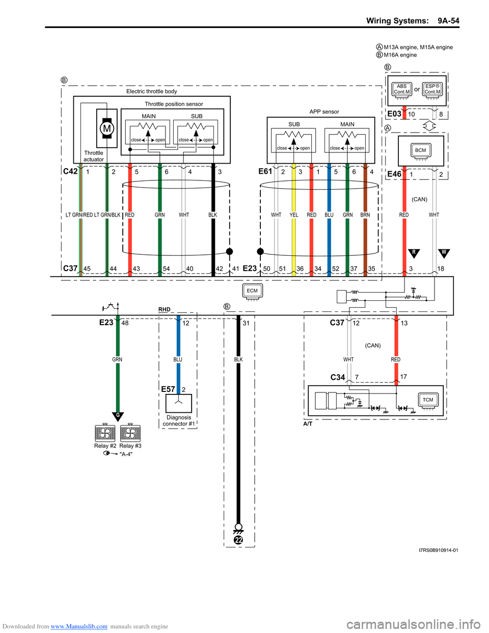
Downloaded from www.Manualslib.com manuals search engine Wiring Systems: 9A-54
BLU
12
Diagnosis
connector #1
E572
ECM
GRN
Relay #2Relay #3
G
"A-4"
E2348
RHD
WHT
BCM
APP sensor
Electric throttle body
Throttle position sensor
SUB
open
close
open
close
open
close
open
close
MAIN
SUB
MAIN
Throttle
actuator
REDBRNGRNBLUREDYELWHTBLKWHTGRNREDLT GRN/REDLT GRN/BLK
E46
3 18
TCM
WHTRED
7 17
C37
C34
1 2
ABS
Cont.MESP
Cont.M
E0310 8
or
E612
3C421 256431564
12 13
RW
5041424054434445513634523735E23
C37
A/T
BLK
31
22
(CAN) (CAN)
M13A engine, M15A engine
M16A engine
AB
B
RB
B
A
I7RS0B910914-01